Page 1229 of 2189
ABS Control Unit
Pulsers/Wheel
Sensors
Replacement
1. Remove the right side kick panel.
2. Disconnect the ABS control unit connecrors.
3. Remove the ABS control unit,
4. lnstall the ABS control unit in the reverse order of
removal,
CONNECTORS
19-76
Inspection
Check the front and rear pulser for chipped or dam-aged teeth.
Measure the air gap between the wheel sensor andpulser all the way around while rotating the pulser.
Slandard: 0.4 - 1.0 mm (0.02 - 0.04 in,
NOTE; lf the gap exceeds 1.0 mm (0.04 in), theprobability is a distorted suspension arm which
should be replaced.
Dbc brake typo
0.{ - 1.0 mm(0.02 - 0.04 in)
Drum brake typ6
1.
Page 1234 of 2189
Doors
Door Panel Replacement
NOTE; Take care not to scratch the door panel and otherpans.
1. Remove:
. Inner handle (see page 20-3)
. Mirror mount cover panel (see page 20-24)
2. lf applicable, remove the regulator handle by pulling
HANOLE
3. Remove the door grip cover and speaker cover, thenremove the screws.
>: Screw locations, 5POWER WTNOOWswtTct{
the clip out with a wire hook.
20-4
4. Release the clips that hold the door panel. Remove
the door panel by pulling it upward.
NOTE: Remove the door panel with as little bending
as possible to avoid creasing or breaking it.
95 mm {3.74 in.)
.L12 mm(0.47 in.) fTRIM PADREMOVER(Commercially
availablelSnap-on#A'177, o.equivalenllmm(0.04 in.l
r_
rr-l
45 mm(1.77 in.l
>i Clip loc.tions, 5
lu-i
J$- I
:fe i
cL,P / IREMovERil I
_ _t/
Dasconnect the;peaker connector,
5. lnstallation is the reverse of the removal procedure.
Page 1236 of 2189

Doors
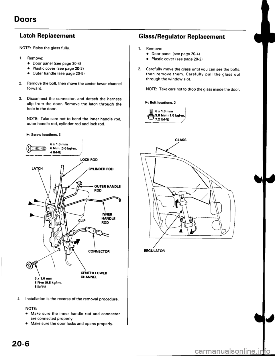
Latch Replacement
NOTE: Baise the glass fully.
1. Remove:
. Door panel (see page 20-4)
. Plastic cover (see page 20-2). Outer handle (see page 20-5)
Remove the bolt, then move the center lower channel
forwa rd.
Disconnect the connector, and detach the harness
clip from the door. Bemove the latch through the
hole in the door.
NOTE: Take care not to bend the inner handle rod,
outer handle rod, cylinder rod and lock rod.
>: Screw locations, 3
6 x 't.0 mm8 N.m (0.8 kgt m,6 tbf.ftl
4. Installation is the reverse of the removal procedure.
NOTE:
. Make sure the inner handle rod and connector
are connected properly.
. Make sure the door locks and opens properly.
LOCK ROO
20-6
'1.
Glass/Regulator Replacement
Removel
o Door panel (see page 20-4)
. Plastic cover (see page 20-2l,
Carefully move the glass until you can see the bolts,
then remove them. Carefully pull the glass out
through the window slot.
NOTE: Take care not to drop the glass inside the door.
>i Bolt loc.tions,2
fi s'r.o-. iClb9.8 N.m 11.0 kst m,l
_-l't!!t ,/
GLASS
REGULATOR
Page 1237 of 2189
\L
3. Disconnect the connector, and detach the harness
clip, then remove the regulator through the hole in
the door,
>: Bolt locations
a>,4
ttt*,
)
6x1.0mm8 N.m {0.8 kgl m,
B>,3
ar Nul locations, 3
It
6x1.0mm8 N.m 10.8 kgf m,6 rbt.ftlLoosen.
REGULATOR{Manualtype)
REGULATOR
4. Grease all the sliding surfaces of the regulator where
snown.
REGULATORMOTOR
lnstallation is the reverse of the removal procedure.
NOTE: Rollthe glass up and down to see if it moves
freely without binding. Also make sure that there is
no clearance between the glass and glass run chan-
nel when the glass is closed. Adjusr the position of
the glass as necessary (see page 20-20).
20-7
Page 1242 of 2189

Doors
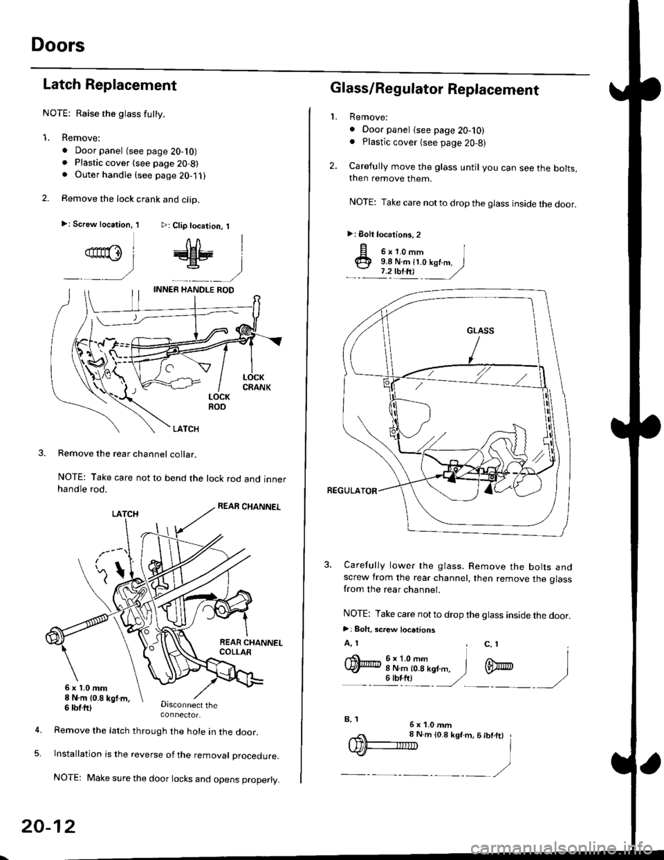
Latch Replacement
NOTE: Raise the glass futty.
1. Remove:
. Door panel (see page 20-10). Plastic cover (see page 20-8). Outer handle (see page 2O-1 ,l
2. Remove the lock crank and clip.
>: Screw location, I >: Clip location, I
qn@l # |
_ __) _-__)
LOCKROO
LATCH
Remove the rear channel collar.
NOTE: Take care not to bend the lock rod and innerhandle rod.
Disconnect theconnector.
6x1.0mm8 N.m (0.8 kgt m,
5.
6 tbtttl
Remove the latch through the hole in lne door.
lnstallation is the reverse of the removat proceoure.
NOTE: Make sure the door locks and opens properly.
20-12
,,< 8 N.m to.8 ksf.m, 6 tbt.ftt
IDF-IIID I
.)-__,/
2.
L
p o'r.o-,n I@ 9.8 N.m {t.o kof.m. I
.- :'zulnt -
/
3. Carefully lower the glass. Remove the bolts andscrew from the rear channel, then remove the glassfrom the rear channel.
NOTE: Take care not to drop the glass inside the door.
>: Bolt. screw locations
A, 1 , c, 1I
q)h:iT(--n,,". i m
- - illt) '/ -)
Glass/Regulator Replacement
Remove:
. Door panel {see page 20-10). Plastic cover (see page 20,8)
Carefully move the glass until you can see the bolts,then remove them.
NOTE: Take care notto drop the glass inside the door.
>: Eolt locations, 2
6x1.0mmB, 1
Page 1243 of 2189

t}
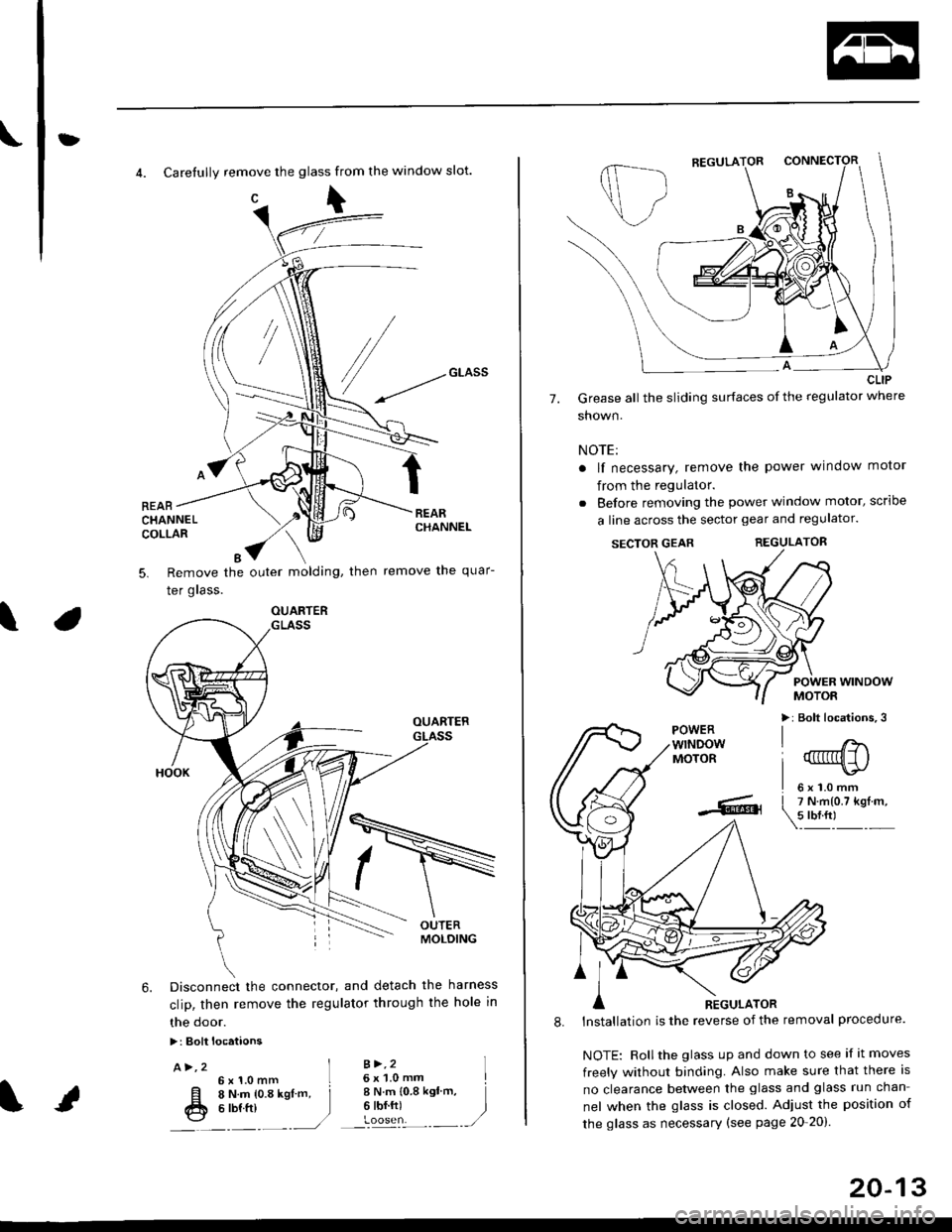
4. Carefully remove the glass from the window slot.
c\
REARCHANNELCOLLAR
Remove the outer molding, then
Ier grass.
remove the quar-5.
\
6. Disconnect the connector, and detach the harness
clip, then remove the regulator through the hole in
the door.
>: Bolt locataons
A>,2 ]6x1.0mm L
[l o t't.- to.a rsl -. j
fr e ttt ttt )---�.---.-,/
B >,26 x 'l.0 mmI N.m {0.8 ksl'm,6 tbf.ft)
I
)
OUARTER
20-13
7.
CLIP
Grease all the sliding surfaces of the regulator where
shown.
NOTE:
a lf necessary, remove the power window motor
from the regulator.
. Before removing the power window motor, scrloe
a line across the sector gear and regulator.
SECTOR GEARREGULATOR
POWER WINDOWMOTOR
>: Bolt locations,3POWERwTNDOWMOTOR
l'
-... er
A nicuuron
8. lnstallation is the reverse of the removal procedure.
NOTE: Rollthe glass up and down to see if it moves
freely without binding. Also make sure that there is
no clearance between the glass and glass run chan-
nel when the glass is closed. Adjust the position of
the glass as necessary (see page 20-20).
Page 1246 of 2189
Doors
Door Panel Replacement
NOTE: Take care not to scratch the door panel andother pa rts.
'1. Remove:
. Inner handle trim (see page 20-14). Mirror mount cover panel (see page 20-24)
2. lf applicable, remove the regulator handle bypulling the clip out with a wire hook.
REGULATOR HANDLE
WIRE HOOK
Remove the armrest pocket, then disconnect thepower window switch connector.
ARMRESTPOCKET
4. Remove the speaker cover, then remove lhe screws.
3.
I
>: Screw locations, 3
| 6b:a,'
L"_
COVER
20-16
TRIM PADREMOVER(Commercially
available)Snap-on#A'177, orequivalent1mm{0.04 in.)
5. Release the clips that hold the door panel. Removethe door panel by pulling it upward. Disconnect thespeaker connector.
NOTE: Remove the door panel with as little bendingas possible to avoid creasing or breaking it.
.L12 fim(0.47 in.) T-
>: Clip locations,
l^
J[
=l$
ll,\*
atr-
,,)
REMoVER tl-)
11.77 in.l
O) CONNECTOR
6. lnstallation is the reverse of the removat oroceoure.
DOOR PANEL
Page 1248 of 2189
Doors
Latch Replacement
NOTE: Raise the glass fully.
1. Remove:
. Door panel (see page 20-16)
. Plastic cover (see page 20-14). Outer handle {see page 20-17}
2. Remove the rod protector.
LATCH
PROTECTOR
20-18
3. Remove the bolts and move the center lower channel.
NOTE: Take care not to bend the inner handle rod
and lock rods.
>: Screw locations
A>,38>,3
q)
CENTER LOWEBCHANNEICBANKHOLDER
Disconnectthe connector,
6x1.0mm8 N.m 10.8 kgt.m,6 tbtft)
Remove the inner handle, then remove the latch
through the hole in the door.
lnstallation is the reverse of the removal procedure.
NOTE: Make sure the door locks and opens properly.
5.
6x1.0mm l
ffu 6 N.m {0.6 kef.m,
_" 11111 )