Page 570 of 2189
lllustrated Index
\
NOTE:
. Whenever the transmission is removed, clean and grease the release bearing sliding surface
. lf the parts marked with an asterisk (*) are removed, the clutch hydraulic system mustbe bled (seepage 12-6)
. Inspect the hoses for damage, leaks, interference, and twisting
'RESERVOIF TANK
ASSIST SPRING
LOCK PIN
5x1,0mm9.8 N.m (1.0 kgf.m,7.2 tbtftl*CLUTCH LINE15 N.m {1.5 kgJ m,11 tbt.ft)
RELEASE BEARINGRemoval/lnspection, page 12-1 1Installation, page 12-'12
*CLUTCH MASTER CYLINDERRemoval/lnstallation, page 12 5
6x1.0mm9.8 N.m (1.0 kgf.m,7.2 tbf.ft)
FLYWHEELInspectaon, page 12IReplacement, Page 12-9
CLUTCH DISCRemoval/lnspection, page 1 2-8
lnstallation, page 12-'10
'12 x 1.0 mm118 N.m {12.0 kgt'm,86.8lbfft)
PBESSURE PLATEBemoval/lnspection, page 12 7Installation, page 12''10
8 x 1.25 mm22 N m (2.2 kgf.m, 16lbf ft)
ISLAVE CYLINDERRemoval/lnstallation, page 12_6
12-3
Page 571 of 2189

Glutch Pedal
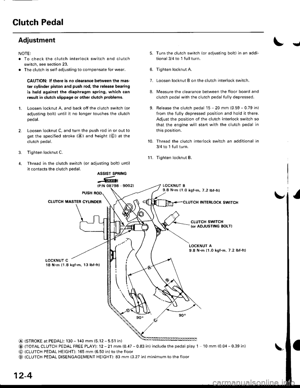
Adjustment
NOTE:
. To check the clutch interlock switch and clutch
switch, see section 23.
. The clutch is self-adjusting to compensate for wear.
CAUTION: lf there is no clearance between the mas-
ter cylinder pislon and push rod, the release bearing
is held against the diaphragm spring, which can
result in clutch slippage 01 other clutch problems.
1. Loosen locknut A, and back off the clutch switch (or
adjusting bolt) until it no longer touches the clutch
peoar.
2. Loosen locknut C, and turn the push rod in or out to
get the specified stroke {@} and height (@) at tne
clutch pedal.
3. Tighten locknut C.
4. Thread in the clutch switch {or adiusting bolt) until
it contacts the clutch pedal.
9002)
Turn the clutch switch (or adjusting bolt) in an addi-
tional 3/4 to 1 full turn.
Tighten locknut A.
Loosen locknut B on the clutch interlock switch.
Measure the clearance between the floor board and
clutch pedal with the clutch pedal fully depressed.
Release the clutch pedal 15 - 20 mm {0.59 - 0.79 in)
from the fully depressed position and hold it there.
Adjust the position of the clutch interlock switch so
that the engine will start with the clutch pedal in
this position.
Thread the clutch interlock switch an additional in
3/4 to 1 full turn.
Tighten locknut B.
LOCKNUT B9.8 N.m (1.0 k91.m,7.2 lbt.tt)
INTERLOCK SWITCI{
J
'lL
5.
7.
8.
9.
10.
ASSIST SPRING
-Atl
CLUTCH SWITCH
lo. ADJUSTING BOLTI
LOCKNUT A9.8 N'm (1.0 kgI.m, 7.2 lbf,ft)
LOCKNUT C18 N.m {1.8 kql.m, 13lbf.ft}
@ (STROKE at PEDAL): 130 - 140 mm (5.12 - 5.51 in)
@ (TOTAL CLUTCH PEDAL FREE PTAYI: 12 - 21 mm (0.47 - 0.83 in) includethepedal play 1 10 mm (0.04 - 0.39 in)
@ (CLUTCH PEDAL HEIGHT): '�]65 mm {6.50 in) to the floor
@ (CLUTCH PEDAL DISENGAGEMENT HEIGHT): 83 mm (3.27 in) minimum to the floor
12-4
Page 572 of 2189
Glutch Master Gylinder
IRemovaUlnstallation
CAU'NON:
. Do not sDill brake lluid onthevehicle;it may damage
the paint; if brake fluid does contact the paint, wash
it off immediatelY with water.
. Plug the end ofthe clutch line and reservoir hos€ with
a shop towelto prevent brake tluid from coming out
1. The brake tluid can be removed from the clutch
master cylinder reservoir with a syringe
2. Disconnect the clutch line and reservoir hose from
the clutch master cylinder.
19N.m 11.9 kgf.m,14 tbf.ttl
[.
3. Pry out the lock pin, and pull the pedal pin out
the yoke. Remove the nuts
NUTS8 x 1 .25 mm13 N.m {'1.3 kgt.m,9.4lbf ft)
)
of
CLUTCH LINE
iffi,
4. Remove the clutch master cylinder.
CLUTCH MASTER CYLINDER
lnstall the clutch master cylinder in the reverse
order of removal.
NOTE: Bleed the clutch hydraulic system {see page
12-61,
12-5
Page 573 of 2189

Slave Gylinder
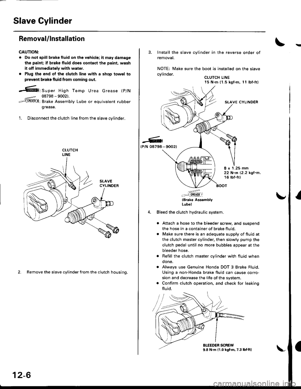
Removal/lnstallation
CAUTION:
. Do not spill brake tluid on the vehicle; it may damage
the paint; if brake fluid does contact th€ paint, wash
it off immodiatoly with water,
. Plug the end ot the clutch line with a shop towel to
prevsnt brake fluid from coming oul.
-61'srp", High Temp Urea crease (p/N
08798 - 90021.
: Brake Assembly Lube or equivalent rubber
grease.
1. Disconnect the clutch line from the slave cvlinder.
2. Remove the slave cylinder from the clutch housing.
12-6
3. Install the slave cylinder in the reverse order of
removal.
NOTE: Make sure the boot is installed on the slave
cvlinder.. CLUTCH LINE15 N.m (1 .5 kgf.m, 1 1 lbf.It)
SLAVE CYLINDER
-G4(P/N 08798- 90021
8 x 1.25 mm22 N.m 12.2 kgl.n,16 lbl.lt)
:^..:i!!!!! :l
(Brak€ AssemblyLubol
Bleed the clutch hydraulic system.
a Attach a hose to the bleeder screw, and suspend
the hose in a container of brake fluid.
. Make sure there is an adequate supply of fluid at
the clutch master cylinder, then slowly pump the
clutch pedal until no more bubbles appear at the
bleeder hose.
. Refill the clutch master cylinder with fluid when
done.
. Always use Genuine Honda DOT 3 Brake Fluid.
Using a non-Honda brake fluid can cause corro-
sion and decrease the life of the system.
. Confirm clutch operation, and check for leaking
flu id.
Page 574 of 2189

Pressure Plate
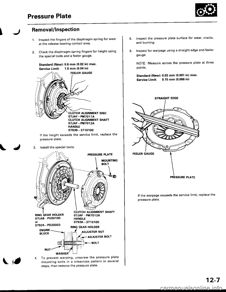
\Removal/lnsPection
1.Inspect the fingers of the diaphragm spring for wear
at the release bearing contact area.
Check the diaphragm spring fingers for height using
the special tools and a feeler gauge.
Standard {New}: 0.6 mm (0.02 inl max.
Seruice Limit: 1.0 mm {0.04 in}
FEELER GAUGE
CLUTCH ALIGNMENT DISCOTJAF_PM7O1 1ACLUTCH ALIGNMENT SHAFTOTJAF-PM7012AHANDLE07936-37tOtOO
lf the height exceeds the service limit, replace the
pressure Plate.
3. Installthe special tools
PRESSURE PLATE
MOUNTINGBOLT
ALIGNMENT SHAFTOTJAF-PM7012AHANDLE07936-371010Oo7924-PD20003GEAR HOLDER
07LA8-PVOOIOOot
ENGINEBLOCKADJUSTER BOLT
BOLT
4. To prevent warping, unscrew the pressure plate
mounting bolts in a crisscross pattern in several
steps, then remove the pressure plate.
f
12-7
lnspect the pressure plate surface for wear' cracks,
and burning.
Inspect for warpage using a straight edge and leeler
ga uge.
NOTEr Measure across the pressure plate at three
pornrs.
Standard (Newl: 0.03 mm (0.001 inl max.
Service Limit: 0.15 mm (0.006 inl
lf the warpage exceeds the service limit, replace the
pressure plate.
STBAIGHT EDGE
Page 575 of 2189
Clutch Disc
RemovaUlnspection
2.
'1. Remove the clutch disc and special tools.
CLUTCH
CLUTCH ALIGNMENT SHAFToTJAF-pM7012A xltori07936-3710100
Inspect lining of the clutch disc for signs of slipping
or oil. lf it is burned black or oil soaked, replace it.
Measure the clutch disc thickness.
Clulch Disc Thickness:
Standard (Now): 8.5 - 9.1 mm (0.33 - 0.36 in)
Servic€ Limit: 5.5 mm (0.22 inl
CLUTCH
lf the thickness is less than the service limit. .eolacethe clutch disc.
12-8
U
4. Measure the depth from the lining surface to therivets, on both sides.
Rivet Depth:
Standard lNewl: 1.3 - 1.9 mm {0.05 - 0.07 in} min.
Service Limit: 0.2 mm (0.01 in)
lf the depth is less than the service limit, replace the
clutch disc.
CLUTCH DISC
Page 576 of 2189

Flywheel
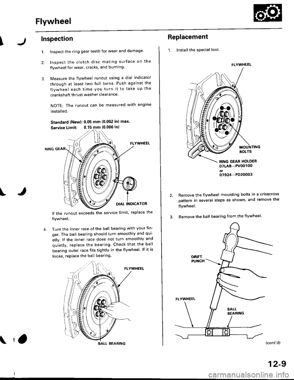
\Inspection
1.
2.
3.
Inspect the ring gear teeth for wear and damage
Inspect the clutch disc mating surface on the
flywheel for wear, cracks, and burning.
Measure the flywheel runout using a dial indicator
through at least two full turns Push against the
flywheel each time you turn it to take up the
crankshaft thrust washer clearance.
NOTE: The runout can be measured with engine
installed.
Standard (New): 0.05 mm (0.002 inl max.
Service Limit: 0.15 mm {0.006 in)
FLYWHEEL
OIAL INOICATOR
FLYWHEEL
lf the runout exceeds the service limit. replace the
flywheel.
Turn the inner race o{ the ball bearing with your tin-
ger. The ball bearing should turn smoothly and qui
etly. lf the inner race does not turn smoothly and
quietly, replace the bearing. Check that the ball
bearing outer race fits tightly in the flywheel. lf it is
loose. replace the ball bearing
IJ
4.
BALL BEARING tO
Replacement
1. Installthe special tool.
MOUNTINGBOLTS
RITIG GEAR HOLDER
oTLAB-PV00100oto7924-PD20003
2.Remove the flywheel mounting bolts in a crisscross
pattern in several steps as shown, and remove the
flywheel,
Remove the ball bearing from the flywheel
(cont'dl
12-9
FLYWHEEL
t\
m\J
Page 577 of 2189
FlywheelClutch Disc, Pressure Plate
Replacement (cont'dl
4. Drive the new ball bearing into the flywheel using
the special tools as shown.
DRIVER07749-0010000
ATTACHMENT,32x35mm07746-OOIOTOO
FLYWHEEL
BEARING
Align the hole in the flywheel with the crankshaft
dowel pin and install the flywheel. Install the
mounting bolts finger-ti9ht.
Install special tool, then torque the flywheel mount-
ing bolts in a crisscross pattern in several steps as
snown.
5.
6.
MOUNTING BOLTS118 N.m (12.0 kgl.m,87 tbf.ft)
RING GEAR HOLDER07LAB-PV00100ol07924 -PO20003
WVa// ,
12-10
Installation
1. Install the special tool.
Y
07936-3710r00
{P/N 08798-90021
RING GEAR HOLDER07LAB-PVOO100ot07924-PD20003
CLUTCH ALIGNMENT SHAFTOTJAF_PM7012A
2.
3.
Installthe clutch disc using the special tools.
Install the pressure plate.
RING GEAR HOLDERoTLAB PV00'l OO
07924 PD20003
OTJAF_PM70124HANOLE07936-3710100
CLUTCH DISC