1996 HONDA CIVIC clutch
[x] Cancel search: clutchPage 62 of 2189

Unit of length: mm lin)
STANDARD {NEW) SERVICE LIMITMEASUREMENT
Differential
Dtri"*"t"|p'.b"gear
S"t rrg-t" b""il"s
Pinion shaft contact area LD.
Carrier-to pinion clearanceDrive shaft contact area l.D.Carrier to driveshaft clearance
BacklashLD.Pinion gear to-pinion shafl clearance
)uter race clearance
18.010 18.028'0.7091 - 0.7098)
0.023 0.057 (0.0009 - 0.0022) 0.1 (0 004)
26.025 - 26.045 (.0246 1 0254\0.045 0.086 (0.0018 - 0.0034) 0.12(0.005)
0 05 - 0.15 i0 002 0.006)18 042 18.066 {0.7103 0.7" l3)
0.055 - 0.095 (0.0022 - 0.0037) 0.15 {0.006)
0 0.15 (0 - 0.006) Adjlrst
MEASUBEMENT Wire DiaO.D. Free Length I No. of Coils
SpringsPH regulator valve spring 1 2 (0 047)
PH control valve spring 1 7 {0.067)PL regulator valve spring 0 9 (0.035)
PH'PL control valve spring 1 0 (0 039)
crutlh reduc'ns vdrve spnns ] :19 9]:lLLbrication valve spring I b (u ubJr
Shitt valve spring 1 4 (0.055)
Shift control valve spring 1 0 (0.039)
Stan clutch control valve spring 0.4 (0 016)
Pitot regulator valve spring 0.6 (0 024)
Start clutch valve accumulator spring 1 2 \0 O47)
Reverse control valve spring 1 2 (0.047)
Shift inhibitor valve spring 1 3 (0 051)
9.0 {0.354)13.4 (0.528)
1.2lO.2A3\10.0 (0.394)
16.8 (0.661)
13.4 (0.528)
8.2 (0.323)
1 .4 t0.29114.1 (0.161)
5.7 t0.224)8.3 {0.327)9.4 (0.370)
13.2 (0.520)
26.7 (1.051)
39.4 (1.551)
14.6 (0.575)
31.4 (1.236)
44.4 \1.14al51.6 (2.031)
34.1 (1.343)
19.3 (0.760)
12.1 (0.476)
9.5 (0.374)
29.8 (1.173)
31.4 (1.236)
48.3 (1.902)
r0.08.11.28.68.0
13.01.56.85.012.311.010.6
Section 14
SteeringSection 17
M/S: [,4anual steering, P/Sl Power steering*: When using a ne; bett, adjust dellection or tension to new values. Run the engine for 5 minutes then turn it off-
Readjust the deflection or tension to used belt values.
cw
MEASUREMENTSTANDARD {NEWI
Steering wheelPlay at steering wheel circumferenceStarting load at steering wheelcircumferenceN (ksf, lbf)Manual steeringPower steering Engine running
0 - 10 (0 0.4)
15 (1.5,3.3)
29 (3.0,6.6)
GearboxAngle of rack guide screw loosened M/S
from locked position P/S
Preload at pinion gear shaft N m (kglcm, lbfin) M/S
20!5"20'Max0.5 - 1.7 (5 - 17,4.3 - 14.8i
0.6 1.2 (6 - 12, 5.20 - 10.42)
Pump pressure with valve closed(oil temp./speed: 40'C (105"F) min./idleDo not run for more than 5 seconds).kPa (kgtcm?, psi)
6,400 - 7,400 {65 - 75, 920 - 1,070)
Power steeringfluidRecommended power steering fluid
Fluid capacity | {US qt, lmp q0Reservoir
HONDA Power Steering Fluid
0.85 (0.90,0.75) at disassembly0.4 {0.42.0.35}
7.5 11.0 {0.30 - 0.43)with used belt
5.0 7.0 (0.20 0.28) with new belt10.5 - 14.0 10.41 - 0.55) with used belt7.5 10.010.30 0.39) with new belt
390 540 {40 55,88 '120) wrth used bek
340 - 490 (35 - 50, 77 - 110) with used belt
740 880 (75 - 90, 170 - 200) with new belt
640 780 (65 - 80, 143-176)with newbelt
Power steeringbelt*
Deflection with 98 N (10 kgf,22 lbf)
between pulleys '99 modell 81642 Engine Type only
'96 '99 models: Other Engine TYPes
ron.ionffiN (kgf, lbf) '99 model: 81642 Engine Tvpe only'96 -'99 models: Other Engine TYPes'99 modelr 81642 Engine TYPe onlY'96 '99 models: Other Engine TYPes
3-17
Page 66 of 2189

trEM I merntc ENGLISH NorEs
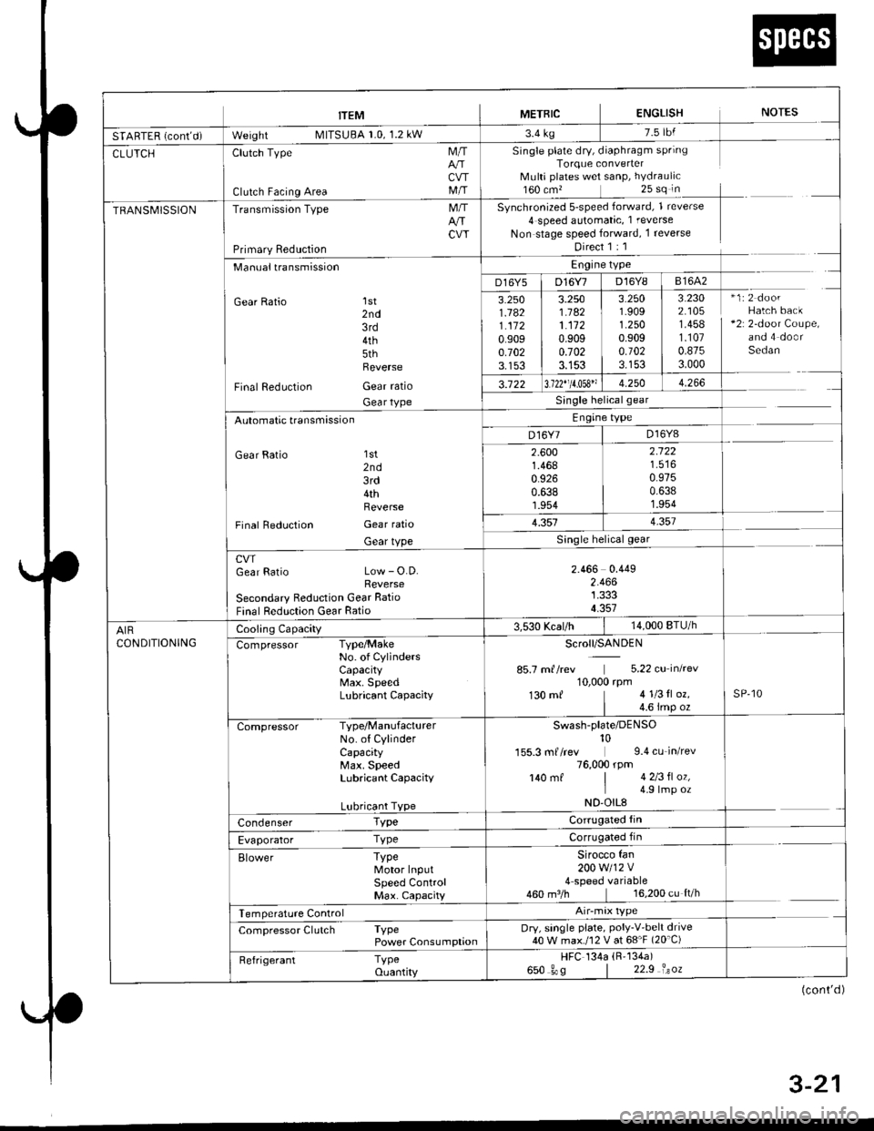
SfAnff n i*nt-i- W"'gf,t MllSUBA r.u, l.z kw r'4 rg
CLUTCHClutch Type
Clutch Facing Area
M/T
CVTM/T
Single plate dry, diaphragm springTorque converterMulti plates wet sanP, hYdraulic160 cm,25 sq in
Synchronized 5-speed forward, 1 reverse
4 speed automatic, 1 reverse
Non stage speed forward, 1 reverse
Direct 1 : 1
TRANSMISSIONTransmission Type
Primary Reduction
M/TArrCW
Manualtransmission
Gear Ratio 1st2nd3rd4th5thReverse
Final Reduction Gear ratio
Gear tYPe
Engine type
D16Y5 | D16Y7 D16Y8 I 81642
3.2501.1821.1120.9090.7023.153
3.2501.1821.1120.9090.7023.153
3.2501.9091.2500.9090.1023.153
3.2302.1051.4581.1070.8753.000
*1:2 doorHatch back+2r 2-door Coupe,and 4 doorSedan
3.122 13.122"11.053" 1 4.250 | 4.266
Single helicalgear
Engine type
D16Y7 | D16Y8Automatic transmission
Gear Ratio 'lst
2nd3rd4thReverse
Final Reduction Gear ratio
Gear tYPe
2.6001.4680.9260.6381.954
2.122
0.9750.6381.954
1.3514.357
cwGear Ratio Low - O.D.Reverse
Secondary Reduction Gear Ratio
Final Reduction Gear Ratio
2.466 0.4492.4661.3334.357
AIRCONDITIONING
Cooling Capacity3,530 Kcal/h14,000 BTU/h
Compressor Type/MakeNo. of CYlindersCaPacitYMax. SpeedLubricant CaPacitY
Scroll/SANDEN
85.7 m//rev 5.22 cu inkev10,000 rpm130 mf 41l3tl oz.
| 4.6 imp ozsP,10
Compressor Type/ManufacturerNo. of CylinderCapacityMax. SpeedLubricant CaPacitY
Lubricant TYPe
Swash-plate/DENso10155.3 mf /rev 9.4 cu_in/rev76,000 rpm140 mf | 4 2l3fl oz,I 4 9lmp ozND'OIL8
Condenser TypeCorrugated fin
Evaporator TyPeCorrugated fin
Elower TyPeMotor InputSPeed ControlMax. CaPacity
Sirocco fan200w112v4 speed variable460 m3/h 16,200 cu ft/h
Temperature Control
Compressor Clutch TyPePower ConsumPtionDry, single plate, PolY-V'belt drive40 W max./12 V at 68'F (20'C)
Refrigerant TyPeouantity
HFC 134a (R'134a)
650 gos | 22.9 isoz
(cont'd )
4 . J-Z I
Page 72 of 2189

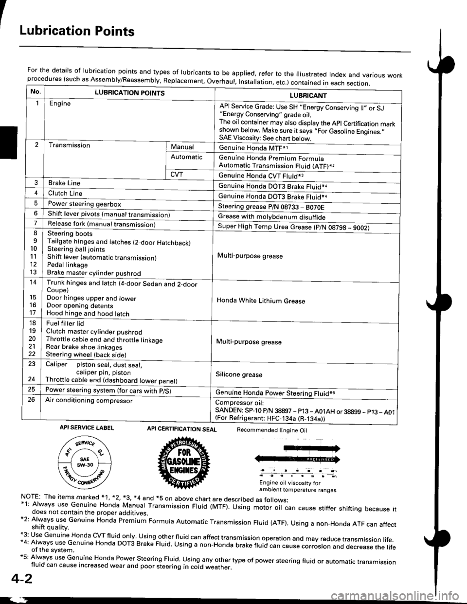
ILubrication Points
For the details of lubrication points and types of lubricants to be applied, refer to the lllustrated Index and various workprocedures (such as Assembly/Reassembly, Replacement, Overhaul. Installation, etc.) contained in each section.
No.LUBRICATION POINTS
Engine
LUBRICANT
"Energy Conserving" grade oil,The oil container may also display the Apl Certification markshown below. Make sure it says ,,For Gasoline Engines.,,SAE Viscosity: See chart below,
I
TransmissionManualGenuine Honda MTF*1
Genuine Honda Premium FormulaAutomatic Transmission Fluid (ATF)*,
Genuine Honda CVT Fluid*3
Genuine Honda DOT3 Brake Fluid*a
Automatic
CVT
3Brake Line
ClL,tci t""e4
I
Genuine Honda DOT3 Brake Fluid*aPower steering gearboxSteering grease P/N 08733 - BO70EShift lever pivots (manual transmission)Grease with molybdenum disulfide7-:ti
9
10'l'l
l3
14
't7
18
19
20
2122
Release fork (manual trancmi
Shift lever (automatic transmission)Pedal linkageBrake master cylinder pushrod
Super High Temp Urea crease (p/N 08798 - 9OO2)
i Multi-purpose grease
I
I
Honda White Lithium Grease
Multi-purpose grease
Silicone grease
@
Trunk hinges and latch (4-door Sedan and 2-doorCoupe)Door hinges upper and lowerDoor opening detentsHood hinge and hood latch-FUet T ter ttd
Clutch master cylinder pushrodThrottle cable end and throttle linkageRear brake shoe linkagesSteering wheel (back side)
23
E-
Caliper piston seal, dust seal,caliper pin. pistonThrottle cable end (dashboard lower panel)
Power steering system (for cars with p/S)
Air conditioning compressorComDressor oil:SANDEN: SPlo P/N 38897 - p13 -A01AH or 38899 - p13_ A01{For Refrigerant: HFC-134a (R-134a))
CERTIFICATION SEAL
ffi
NorE: The items m arked * 1, *2, +3, *4 and +5 on above chan are described as folows:*1: Always use Genuine Honda Manual Transmission Fluid (MTF). Using motor oil can cause stiffer shifting because itdoes not contain the proper additives.*2: Always use Genuine Honda premium Formula Automatic Transmission Fluid (ATF). Using a non-Honda ATF can affectshift quality.+3: Use Genuine Honda cVTfluid only usingotherfluid can affect tra nsmission operation and may reduce transmission life.*4: Always use Genuine Honda DoT3 Brake Fluid. Using a non-Honda brake fluid can cause corrosion and dec.ease the lifeof the svstem.*5: Always use Genuine Honda Power steering Fluid. using any other type of power steering fluid or automatrc transmissionfluid can cause increased wear and poor steering in cold weather.
4-2
Recommended Engine Oil
Engine oil viscosity forambrent temperature ranges
API SERVICE LABEL
Page 100 of 2189

Engine Removal/lnstailation
Removal (cont'dl
Dl6Y5. DrGYr, D16Y8 enginas:
-1. Remove the mounting bolt and lock bolt, thenremove the P/S pump belt and pump.
MOUNTING BOLT8 x 1.25 mm24 N.m {2.4 kgl.m, 17 tbf.ftl
LOCK BOLT8 x 1.25 mm24 N.m 12.4 kgf.m, 17 lbf.ftl
17. Loosen the idler pulley center nut and adjustingbolt, then remove the air conditioning (A[/C)compressor belt.
IDI.IR PULLEY CENTERNUT10 x 1.25 mma,l N.m {,1.5 kgt.m, 33 lbf.ft)
5-6
(
'18. Remove the ransmission ground cable and hosect8mo.
HOSE CLAMP6 x '1.0 mm
19. Remove the clutch slave cylinder and line/hoseassembty (M/T).
NOTE:
. Do not disconnectthe pipe/hose assembly.. Do not operate the clutch pedal once the slavecylind€r has been removed.o Take care not to bend the line.
6x1,0mm 8x1.2Smm11 N.m {1.1 kgt.m, 2a N.m t2.4 kgf.m,I tbf.ftl 17 tbf.ftl
8 x 1.25 mm2a N'm {2,4 kgt m,17 tbt.ftl
Page 270 of 2189

!
Fuel and Emrsslons
SoecialToofs .....,...."..,. 11-2
Component Locations
lndex ....................., ......... 11-3
Svstem Description
Vacuum Connections ................,,..,.. ......... 11-12
Electrical Connections ...............,.,.,... ....... 11-29
System Connectors ........,.,.,.......................... 1 1-51
Troubleshooting
Troubleshooting Procedures ................. .. 11-81
Engine Control Module/PowertrainControl Module TerminalAfiangement ....,.,..... 11-88
Diagnostic Trouble Code Chart .................,., 11.97
How to Read Flowcharts .,.......................... . 11-103
PGM-Fl System
System Description ...... 11-10,1
Troubleshooting Flowcharts
Engine Control Module/PowertrainContlol Module ........ 11-107
Manitold Absolute Pressure Sensor .....'. . ... 11-115
fntake Air Temperatuie Sensor ..... . . ., . 11'121
Engine Coolant Temperatuae Sensol ........., 11-128
Throttle Position Sensor ...................,........... 11-132
Primary Heated Orygen Sensor (Sensor 1l ... 11-139
Secondary Heated Oxygen Sensor(Sensor 21.................................................... 1 1-153
Heated Oxygen Sensor Heater ...................,. 11-157
Fuel Supply System ...... 11-164
Random Mislire ......., ..11-166
Misfire Detected in One Cylindsr ................. 11-167
Knock Sensor .,.,............ 11-170
CKP/TDC/CYP Sensor ................................... 11'172
Vehicle Speed Sensor ...........,......,...,.,........... 1t-176
Barometric Pressure Sensor ...............,......... I 1-178
Electrical Load Detector,.,,............................ 1 1-179
CKF Sensor .................... 11-183
ECM/PCM Internal Circuit ............................. I 1-188
A/T Signal {TMA/TMBI .................................. I 1-189
ldle Control System
System Doscriplion ............ 11-190
Troubleshooting Flowcharts
ldle Control System ...... 11-192
ldle Air Control Va1ve .................................... I 1-19i1
Starter Switch Signal .................................... 1 1'202
Air Conditioning Signal ................................. 11'201
Ahernator FR Signal .................................... . 1 1-208
BrakeSwitch Signal ..................................... f 1"210
Power Sleering Prossure Switch Signal ......11-212
A/T Gear Position Signal ............................... 11-216
Clutch Swiich Signal ................................-.... 11-214
ldte Speed Setting . .............11-220
Fuel Supply System
Fuel Lines .,...................,.,.,.,11-221
Fuef Tube/Ouick-Connect Fittings ..........,.,........ 11 -227
System Description ....'.... 11-230
Fuel Pressure .......,.,,........... 11-230
Fuef fniectors ......................11-232
Fu€f Pressure Regulator .....,.......................'...,. 11-231
Fuef Fifter ............................11-235
Fuel Pump .............'.......'.... 11-236
PGM-FI Main Relay .............11'237
Fuel Tank ................ ....,...'.'.' 11'211
Intake Air System
System Description ....-.-.....11-243
Air Cfeaner ...........,......."". .11-211
Throttle Cable .....................11-211
Throttfe Body ........ ..'... . . .,.11-211
Fuel Iniestion Air Control System ,.,.,....-........... 11-250
Emission Control System
System Description .-..........11-252
Taifpip€ Emission ...............11-252
Three Way Catafytic Convert€r ............,.,,.,.,.,.... 11 -252
Exhaust Gas Racirculaiion System ...,.,,,,.,.,.,.,,. 11'254
Positive Crankcas€ Ventilation System .... . . .. 11-266
Evaoorative Emission Controls ..................,,..,.,. 11 -267
Page 276 of 2189

I
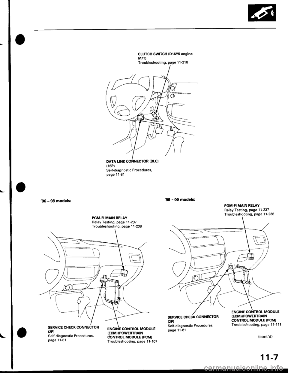
CLUTCH SWITCH lDl6Y5 onginoM,/TITroubleshooting, page 1 1-218
'96 - 98 modsls:
Sell-diagnostic Procedures.page 11 81
ENGINC CONTROL MOOUI.T(FCMI/POWERTRATN
CONTROL MODULE IPCMITroubleshooting, page 1 1-107
'9!, - 0o modol3:
PGM.FI MAIN RELAYRslay Testing, page 11-237Troubleshooting, page 1 1-238PGM.FI MAIN RELAYRelay Testing, page l1 237Troubleshooting, pago 1'! 238
SERVICEl2Pl
CONNECTOR
ENGINE CONTROL MODU1T(ECM}/POWERTRAIN
CONTROL MODULE IPCMITroubleshooting, page 11 111SERVICE CHECK CONNECTORtzPlSelf-diagnostic Procedures,page 11-81
Self-diagnostic Procedures,page 11-81
{cont'd)
11-7
Page 302 of 2189
![HONDA CIVIC 1996 6.G Workshop Manual PSP SWITCHI
c1t7
atu/wHT =..-_/YEL Jlr.^r\-r IwHr---] FaMrr=ll
L_id-ll8r-x,--L- |
CAI\IISTER VENT
tr--+r-* I=
calT_ 66s fr:-ll-BL!(--- - lf.a - ICLUTCH SWTCHX_-o_
I(contd)
1 1-33
IT GRN/WI{T
HONDA CIVIC 1996 6.G Workshop Manual PSP SWITCHI
c1t7
atu/wHT =..-_/YEL Jlr.^r\-r IwHr---] FaMrr=ll
L_id-ll8r-x,--L- |
CAI\IISTER VENT
tr--+r-* I=
calT_ 66s fr:-ll-BL!(--- - lf.a - ICLUTCH SWTCHX_-o_
I(contd)
1 1-33
IT GRN/WI{T](/manual-img/13/6068/w960_6068-301.png)
PSP SWITCHI
c1t7
atu/wHT =..'-_/YEL Jlr.^r'\-r IwHr---] FaMrr=ll
L_id-ll8r-x,--L- |
CAI\IISTER VENT
tr--+r-*' I=
calT_ 66s' fr:-ll-BL!(--- - lf.a - ICLUTCH SWTCH'X_-o_
I(cont'd)
1 1-33
IT GRN/WI{T
ctor
Page 354 of 2189

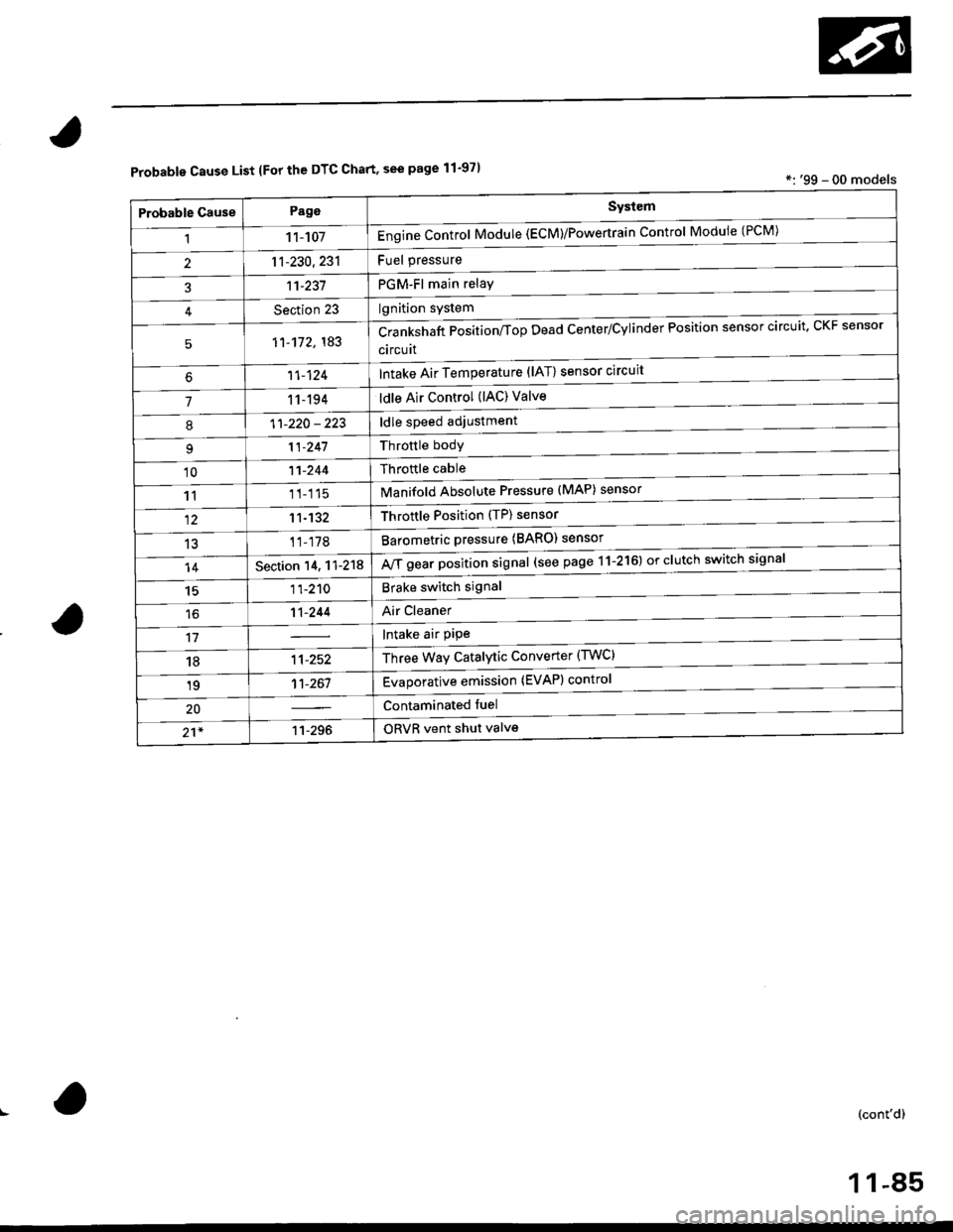
Probable Cause List lFor th€ DTC Chart, see page 11-971*: '99 - 00 models
Probable GausePageSystem
11 1-107Engine Control Module (ECM)/Powertrain Control Module (l'uM)
PGM-Fl main relay
l^^iti^n cwetam
211-230,231
3't't-237
Section 23
51'�1-172,183Crankshaft Position/fop Dead Center/Cylinder Fosltlon sensor clrculr'� Lr\F selrsor
circuit
Intake Air Temperature (lAT) sensor circuit
ldle Air Control (lAC) Valve
ldle speed adjustment
Throttle bodY
Throftle cable
Manifold Absolute Pressure (MAP) sensor
Throftle Position (TP) sensor
Barometric pressure (BARO) senso'
Mf g"a, po"ition signal (see page 11-216) or clutch switch signal
Brake switch signal
Air Cleaner
lntake air pipe
Three Way Catalytic Converter (TWC)
Evaporative emission (EVAP) control
Contaminated fuel
ORVR vent shut valvs
't1-124
71 1-194
I11-220 - 223
11-241
'1011-244
1111-115
1211-132
13't1-178
14Section 14. 11-218
1511-210
16't1-244
1811-252
1911-261
20
21*11-296
(cont'd)
11-85