Page 190 of 2189

t
Valve Guides
Replacement
1. As illustrated below, use a commerciallv available
air-impact valve guide driver attachment modified
to fit the diameter of the valve guides. ln most
cases, the same procedure can be done using the
sDecial tool and a conventional hammer.
COMMERCIALLY AVAILABLEVALVE GUIDE DRIVER
87 mm -L- sz mm(3.43 inl I tz.zr int
rE-tt
10.8 mm10.42 inl
olVALVE GUIOE DRIVER,5.5 mm077,P - 0010100
Select the proper replacement guides and chill
them in the freezer section of a refrigerator for
about an hour.
Use a hot plate or oven to evenly heat the cylinder
head to 300"F (150"C). Monitor the temperature with
a cooking thermometer.
CAUTION:
. Do not use a torch; it may warp tho head.. Do not get tho head hotter than 300"F {150"C};excesgive heat may loosen thg valve seats.. To avoid burns. use haaw gloves whon handling
the heatod cylinder head.
6-80
Working from the camshaft side, use the driver and
an air hammer to drive the guide about 2 mm (0.1 in)
towards the combustion chamber. This will knock off
some ofthe carbon and make removaleasier.
CAUTION:
. Always wsar safety goggles or a face shield whsn
driving valve guides.
. Hold the air hammer dir€ctly in line with the
valve guide to prevont damaging thg dtiver.
Turn the head over and drive the guide out toward
the camshaft side of the head.
VALVE GUIOE DRIVER,5.5 mm077{2 - 0010100
lf a valve guide still won't move. drill it out with a8.0 mm (5/16 in) bit, then try again.
CAUTION: Drill guides only in extreme cases; you
could damago the cylinder head if ths guide br6aks.
Remove the new guide(s) from the freezer, one at a
time, as vou need them.
-:^-,65i^q
NNSp-<
Page 235 of 2189

Oil Pressure
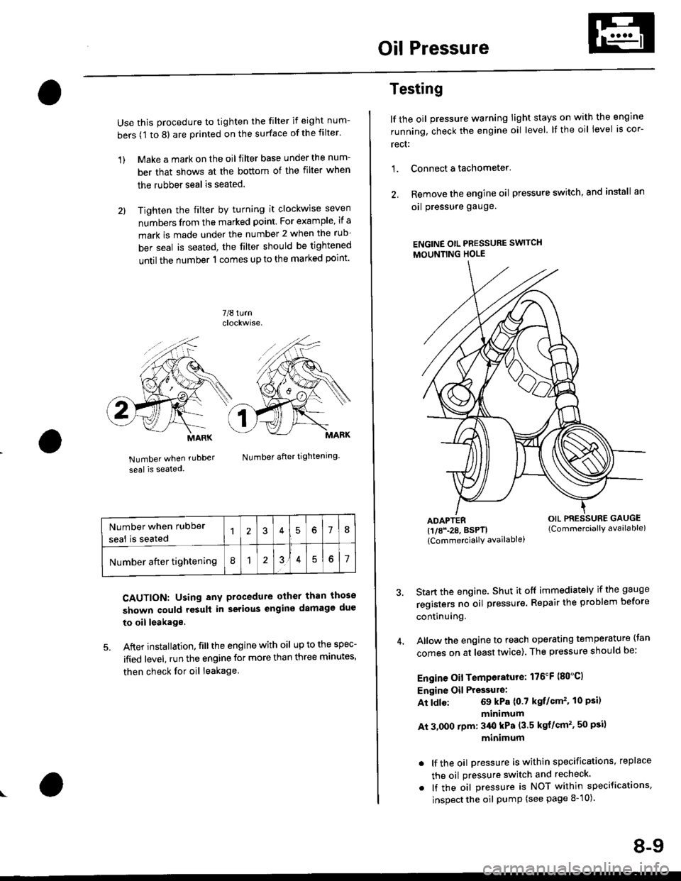
Use this procedure to tighten the filter if eight num-
bers (1 to 8) are printed on the surface of the filter.
1) Make a mark on the oil filter base under the num-
ber that shows at the bottom of the filter when
the rubber seal is seated.
2l Tighten the filter by turning it clockwise seven
numbers from the marked point. For example, if a
mark is made under the number 2 when the rub
ber seal is seated, the filter should be tightened
until the number 1 comes up to the marked point'
7/8 turn
Number when rubDer
seal is seated
Number after tightening.
CAUTION: Using any procedure other than those
shown could rosult in serious engins damage due
to oil leakage
5. After installation. fill the engine with oil up to the spec-
ified level, run the engine for more than three minutes,
then check for oil leakage
MARK
Number when rubber
seal is seated578
Number after tightening8151
Testing
lf the oil pressure warning Iight stays on with the engine
running, check the engine oil level. It the oil level is cor-
rect:
1. Connect a tachometer'
2. Remove the engine oil pressure switch, and install an
oal pressure gauge.
ENGINE OtL PRESSURE SWITCH
MOUNTING HOLE
ADAPTER(1/8\28. BSPTI
{CommerciallY availablei
Start the engine. Shut it off immediately if the gauge
registers no oil pr€ssure. Repair the problem before
continuing.
Allow the engine to reach operating temperature (tan
comes on at least tlivice). The pressure should be;
Engine Oil Temperature: 176"F (80"C1
Engine Oil Pressulo:
At ldle: 69 kPa (0.7 kgf/Gm'�. 10 Psi)
minimum
At 3.000 rpm: 3/Ut kPa (3.5 kgt/cm'�, 50 psi)
minimum
. lf the oil Dressure is within specifications, replace
the oil pressure switch and recheck.
. lf the oil pressure is NOT within specifications,
inspect the oil pump (see page 8-10).
OIL PRESSURE GAUGE(Commerciallv available)
8-9
Page 236 of 2189
OilJet (B1642 engine)
Inspection
1.Remove the oil jet (see page 8-3) and inspect it asfollows.
Make sure that a 1.1 mm (0.04 in) diameter drillwill go through the nozzte hole (j.2 mm (0.05 in)diameter).
Insert the other end of the same 1.1 mm (0.04 in)drill into rhe oil intake (i.2 mm (0.05 in) diame_ter).
Make sure the check ball moves smoothly andhas a stroke of approximately 4.0 mm (0.16 in).Check the oil jet operation with an air nozzle. ltshould take at least 200 kPa (2.0 kgf/cm,, 28 psi)to unseat the check ball.
NOTE: Replace the oil jet assembly if the nozzlers damaged or bent.
CHECK BALLSPRING16 N.m 11.6 kgf,m, t2 tbf.fil
Mounting torque is critical. Be very precise wheninstalling.
Torque: 16 N.m (1.6 kgt.m, 12 tbt.ft)
1.2 mm (0.05 inl
8-10
Page 239 of 2189

4.
Removal/lnspection/lnstallation
2.
3.
1.
5.
6.
1.
8.
Drain the engine oil.
Turn the crankshaft and align the white groove on
the crankshaft pulley with the pointer on the lower
cover.
Remove the cylinder head cover and upper cover'
Remove the power steering pump belt, air condi-
tioner beit and the alternator belt
Remove the crankshaft pulley and remove the lower
cover.
Remove the timing belt.
Remove the drive pulley.
Remove the oil pan and oil screen.
O.RINGReplaceOOWEL PIN
OIL SCREEN
9. Remove the oil PumP.
!'a
10.Remove the screws from the pump housing, then
separate the housing and cover'
Check the inner-to-outer rotor radial clearance on
the pump rotor. lf the inner-to outer rotor clearance
exceeds the service limit, replace the inner and
outer rotors.
lnner Rotor-to-Outer Rotor Radial Clearance
Standard {New}: 815A2 engine 0.04 - 0.16 mm
(0 002 - 0'006 in)
D16Y5, D16Y7, D16Y8 engines
0.02 - 0.14 mm 10.001 - 0.006 in)
Service Limit: 0.20 mm (0 008 inl
OUTER ROTOR
INNER ROTOR
Check the housing-to-rotor axial clearance on the
pump rotor. lf the housing-to rotor axial clearance
exceeds the service limit, replace the set of inner
and outer rotors and/or the pump housing
Housing-to-Rotor Axial Clearance
Standard (N€w): 816A2 engine 0.02 - 0.07 mm
(0.001 - 0.003 inl
D16Y5, D16Y7, D16Y8 engines
0.03 - 0.08 mm (0.001 - 0.003 inl
S€rvice Limit: 0.15 mm 10.006 in)
11.
't2.
(cont'd)
8-13
Page 245 of 2189
lntake Manifold
Replacement (cont'dl
NOTE: Use new O,rings and gaskets when reassembling.
CAUTION:
. Check lor folds or scratches on the surface of the gasket.. Replace with a new gasket il damaged.
D16Y8 engine:
INTAKE MANIFOLDReplace if cracked orif mating surfaces areoamageo,
INTAKE AIR CONTROL{ract vAt_vE {M/Tl
GASKETReplace.
8 x 1.25 mm24 N.m {2.{ kgtm.17 tbtftt
THROTTLEBODY
8 x 1.25 mm22 N.rn |.2.2 kgl.rn,16 tbtft)INTAKE MANIFOLDBRACKET
9-4
Page 246 of 2189
816A2 engine:
INTAKE MANIFOLDReplace if cracked orif mating surfaces areoamageo,
8 x 1.25 mm22 N.rA 12.2 kgl.trr,16 tbtftt
o
t_-lUH
E
INTAKE AIR CONTROLIIACI VALVE
8 x 1.25 mm24 N.m 12.4 kgf.m,17 tbtftl
8 x 1.25 mm23 N.m {2.3 kg{.m,17 tbt.ftl
Al N-m 12.2 kgt.m,16 tbt.ftlMANIFOLDBRACKET
n ""\--
VlCd>-^
M\G
yo
9-5
Page 257 of 2189

lllustrated Index
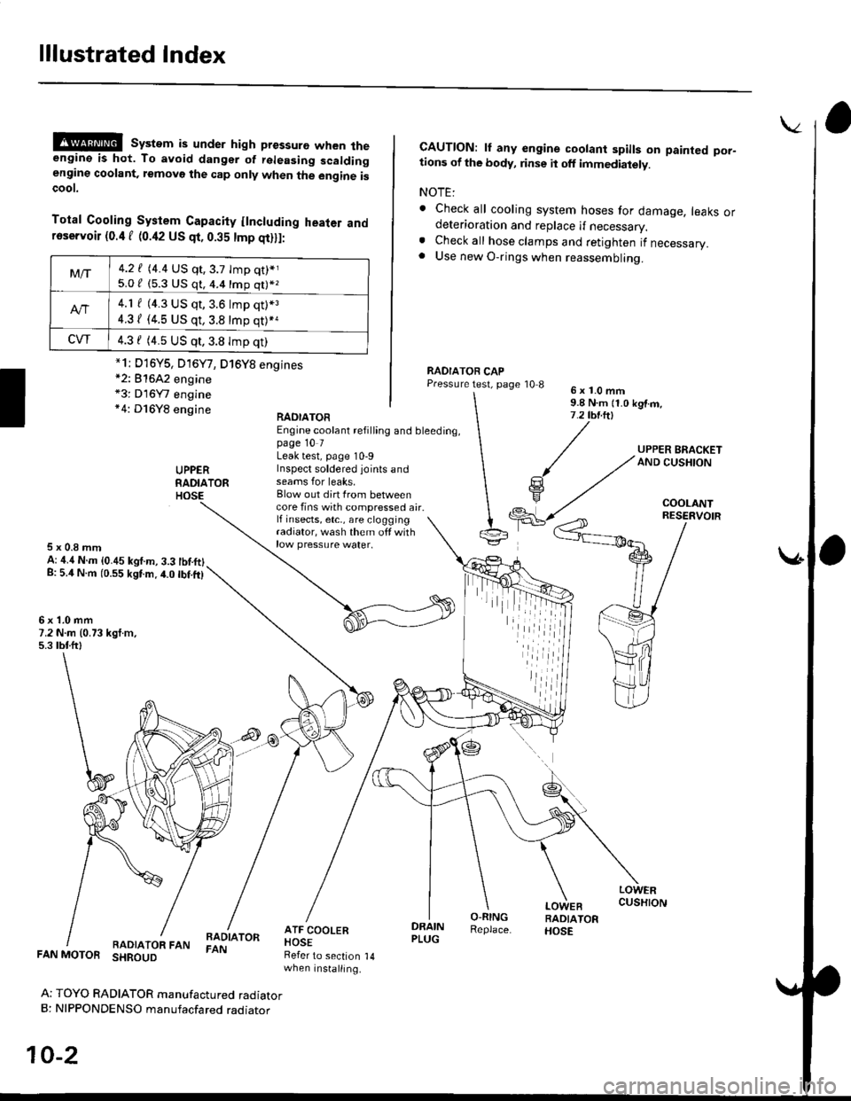
@@ system is under high pressure when theengine is hot. To avoid dangsr of rsleasing scaldingengine coolant, removo the cap only when the engine iscoot.
Total Cooling System Capacity flncluding heater andfoservoir (0.4 f (0.42 US qt, 0.35 tmp qt)ll:
*2: 81642 engine*3: D16Y7 engine*4: D16Y8 engine
CAUTION: lf any engine coolant spills on painted por-tions of the body, rinse it off immediately.
NOTE:
. Check all cooling system hoses for damage, leaks ordeterioration and replace if necessary.. Check all hose clamps and retighten if necessary.. Use new O-rings when reassembling.
RADIATOR CAPPressure test, page '10 86x1.0mm9.8 N.m {1.0 kgtm,7.2 tbt.ltl
UPPERRADIATORHOSE
UPPER BRACKETAND CUSHION
COOLANT
RAOIATOREngine coolant refilling and bleeding,page 10 7Leak test, page 10-9Inspect soldered joints andseams for leaks,Blow out dirt Irom betweencore fins with compressed air.lf insects, etc,, are cloggingradiator, wash them off withrow pressure water.
RESERVOIR
5x0.8mmA: ,1.4 N.m {0.45 kgf.m, 3.3 tbtftlg: 5.4 N.m (0.55 kgtm.4.0 tbf.ft)
6x1.0mm7.2 N.m (0.73 kgt.m,5.3 tbtftl
LOWERCUSHION
RADIATOR FANBADIATORFAN
DRAINPLUG
O-RINGReplace.
LOWEBRADIATORHOSE
FAN MOTOR SHROUD
Ar TOYO RADIATOR manufactured radiatorB: NIPPONDENSO manufacfared raoraror
10-2
Refer to section 14when installing.
Mt-|-4.2 f (4.4 US qt,3.7 tmp qt)*j
5.0 / (5.3 U$ q1, 4.4 16p q11*z
4.1 f (4.3 US qt, 3.6 lmp q0*3
4.31 (4.5 US qt, 3.8 tmp qt)*a
CVT4.3 f (4.5 US qt,3.8 Imp qt)
*1i D16Y5, D16Y7, D16Y8 engines
iil
Page 261 of 2189
Radiator
Replacement
Drain the engine coolant.
Remove the upper and lower radiator hoses, andATF cooler hoses.
Disconnect the fan motor connector.
Remove the radiator upper bracket, then pull up theraotator,
RADIA
ATF COOLERHOSES (A/T)Refer to sectionwhen installing.
UPPER RAOIATOR HOSE
6x1.0mm7.2 N.m (0.73 kgf.m.5.3 tbf.ft)
1.
2.
3.
5. Remove the fan shroud assemblies and other partsfrom the radiator.
Install the radiator in the reverse order of removal:
NOTE:
. Set the upper and lower cushions securely.. Fill the radiator with engine coolant and bleedthe air.
6x1.0mmCAPY|lT,PS:|" i.i ru- ii b rgr.-,AND CUSHION7.2 tbr.ftl
14
(
I
RESEBVOIR TANK
RADIATOR
LOWER CUSHION
RAOIATOR FAN/SHROUDASSEMBLY
DRAIN PLUGO-RINGReplace.
LOWER RAOIATOR HOSE
ATF COOLERPIPES {A/T)
,iiiiii
10-6