Page 1013 of 2189
Ring Gear BearingControl Shaft Assembly
Replacement
1. Remove the ring gear bearing.
RING GEAR
Install the new ring gear bearing until it bottoms in
the ring gear. using the specialtools as shown,
DRIVER07?{9 - 001(xxxt
RING
14-336
RemovaUlnstallation
1. Remove the bolt and lock washer.
CONTROL SHAFTASSEMBLY
6r1.0mm14 N.ft 11.4 kg{.m,10 rbf.ftl
TRANSMISSION
CONTROLLEVER
LOCK WASHERReplace.
2. Remove the control lever from the control shaft.
3. Remove the control shaft assembly.
4. Install the control shaft assembly in the transmission
housing.
Install the control lever to the control shaft.
Install and tighten the bolt with a new lock washer.
Page 1014 of 2189
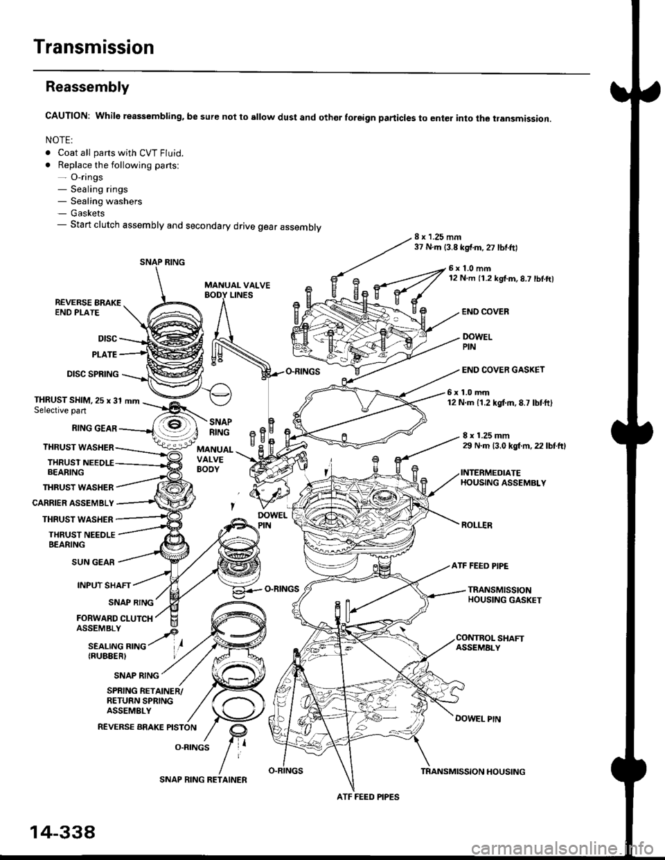
Transmission
Reassembly
CAUTION: While reassembling. be sure not to sllow dust and othor foreign particles to enter into the transmission.
NOTE:
. Coat all parts with CVT Fluid.
. Replace the following parts:- O-rings- Sealing rings- Sealing washers- Gaskets- Start clutch assembly and secondary drive gear assembly8 x 1.25 mm37 N.m {3.8 kgf.m,27 lbtftl
MANUAL VALVE
6x1.0mm12 N m 11.2 kgf.m,8.7 lbl.ft)
LINESREVERSE BRAKEEND PLATE
Dtsc
PLATE
DISC SPRING
THRUST WASHER
CARRIER ASSEMBLY
THRUST WASHER
THRUST NEEDLEBEARING
END COVEB
DOWELPIN
END COVER GASKET
6x1.0mm12 N.m 11.2 kgtm,8.7 lbtft)THRUST SHIM,25 x 31 mmSelective part
RING GEAR
THRUST WASHER
THRUSTBEARING
8 x 1.25 mm29 N.m 13.0 kgl m, 22 lbtftl
INTERMEDIATEHOUSING ASSEMBLY
ROLI.IR
SNAPRINGeBH^cMANUALVALVEBOOY
SUN GEAR
INPUT SHAFT
(RUBEERI
ATF FEED PIPE
O-RINGSTRANSMISSIONHOUSING GASKETSNAP RING
FORWARD CLUTCH
SNAP RING
SHAFTASSEMALY
DOWEL PtN
SPRING RETAINER/RETURN SPRINGASSEMBLY
REVERSE BRAKE PISTON
O.RINGS
SNAP RING
ATF FEED PIPES
14-338
SNAP RING RETAINERTRANSMISSION HOUSING
Page 1016 of 2189
Transmission
16.
Reassembly (cont'dl
21.
17.
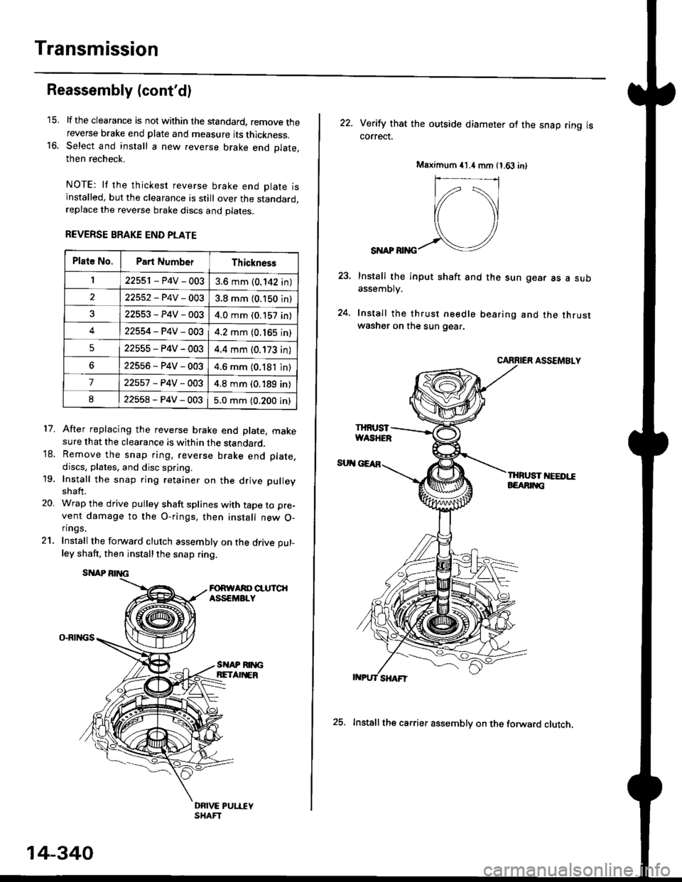
lf the clearance is not within the standard, remove thereverse brake end plate and measure its thickness.Select and install a new reverse brake end Dlate.then recheck.
NOTE: lf the thickest reverse brake end olate isinstalled, but the clearance is still over the standard,replace the reverse brake discs and plates.
REVERSE BRAKE END PLATE
After replacing the reverse brake end plate, makesure that the clearance is within the standard.Remove the snap ring, reverse brake end plate,
discs, plates. and disc spring.
Install the snap ring retainer on the drive pulley
shaft.
Wrap the drive pulley shaft splines with tape to pre-
vent damage to the O-rings, then install new O-n ngs.
Install the forward clutch assembly on the drive pul-
ley shaft, then installthe snap ring.
SITAP
O-RINGS
18.
19.
20.
SI{AP RIM;BETA EB
DRIVE PUI.IEYSHAFT
Plat6 No.Part NumberThickness
122551 - P4V - 0033.6 mm (0.142 in)
22552-P4V-0033.8 mm (0.150 in)
22553-P4V-0034.0 mm (0.157 in)
422554-P4V-0034.2 mm (0.165 in)
522555-P4V-0034.4 mm (0.173 in)
622556-P4V-0034.6 mm (0.181 in)
722557 -P4V -OO34.8 mm (0.189 in)
822558-P4V-0035.0 mm (0.200 in)
14-340
25. Installthe carrier assembly on the forward clutch.
22. Verity that the outside diameter ol the snap ring iscorrect.
SI{AP RIiIG
Install the input shaft and the sun gear as a subassemDry.
Install the th.ust needle bearing and the thrustwasher on the sun gear.
CARRIER ASSEMBLY
THFUST I'IEEDI!EEARIT{G
Msximum 41.4 mm 11.63 in)
IHruST
Page 1024 of 2189
Transmission
Installation
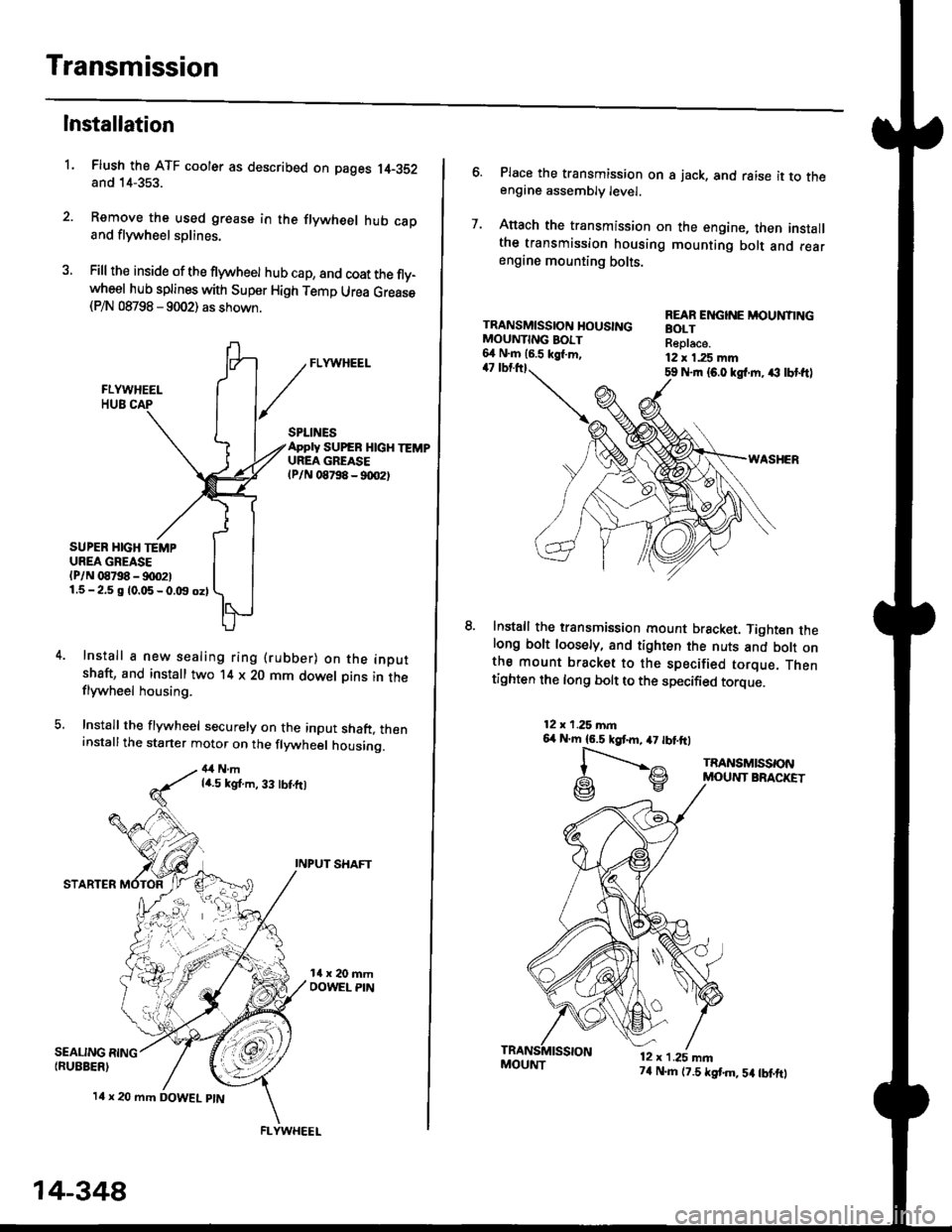
Flush the ATF cooler as described on pages 14-352and 14-353.
Remove the used grease in the flywheel hub caDand flywheel splines.
Fill the inside of the flywheel hub cap, and coat the fly-wheel hub splines with Super High Temp Urea Grease(P/N 08798 - 9002) as shown.
L
SEALING RING{RUEBER)
SPLINESApply SUPEB HlcH TEMPUREA GREASElPlN 08798 - 90O2t
SUPER HIGH TEMPUREA GREASE(P/N 08798 - !)00211.5-2.5 g 10.05-0.t9 oz)
Install a new sealing ring (rubber) on the inoutshaft, and install two '14 x 20 mm dowel Dins in theflywheel housing.
Install the flywheel securely on the input shaft, theninstallthe starter motor on the flywheel housing.
4,1Nmla.5 kgt.m, 33 tbt.ft)
INPUT SHAFT
STARTER
l4 x 20 mm DOWEL ptN
.4;i "lrj
,i rr,"r., ., a
14-348
FLYWHEEL
MOUI{T74 N.m (7.5 tstm,5a tbtftt
6. Place the transmission on s jack, and raise it to theengine assembly level.
7. Anach the transmission on the engine, then installthe transmission housing mounting bolt and rearengine mounting bolts.
TRANSMISSION HOUSINGMOUNTING BOIT6,1 N.m 16.5 kgl.m,47 tbtttl59 Nrn {6.0 kgl.m. ,€ lbt ftl
WASHER
lnstall the transmission mount bracket. Tighten thelong bolt loosely, and tighten the nuts and bott onthe mount bracket to the specified torque. Thentighten the long bolt to the specified torque.
REAR ENGINE MOUNTINGBOLTReplace.12 x 1.25 mm
12x 1.25 mn6,r N'm 16.5 kgtm,47 tbtftl
l-".--..-,^
G\V
TRANSMISSONMOUNT BRACKET
12 x 1.25 mn
Page 1025 of 2189
l.
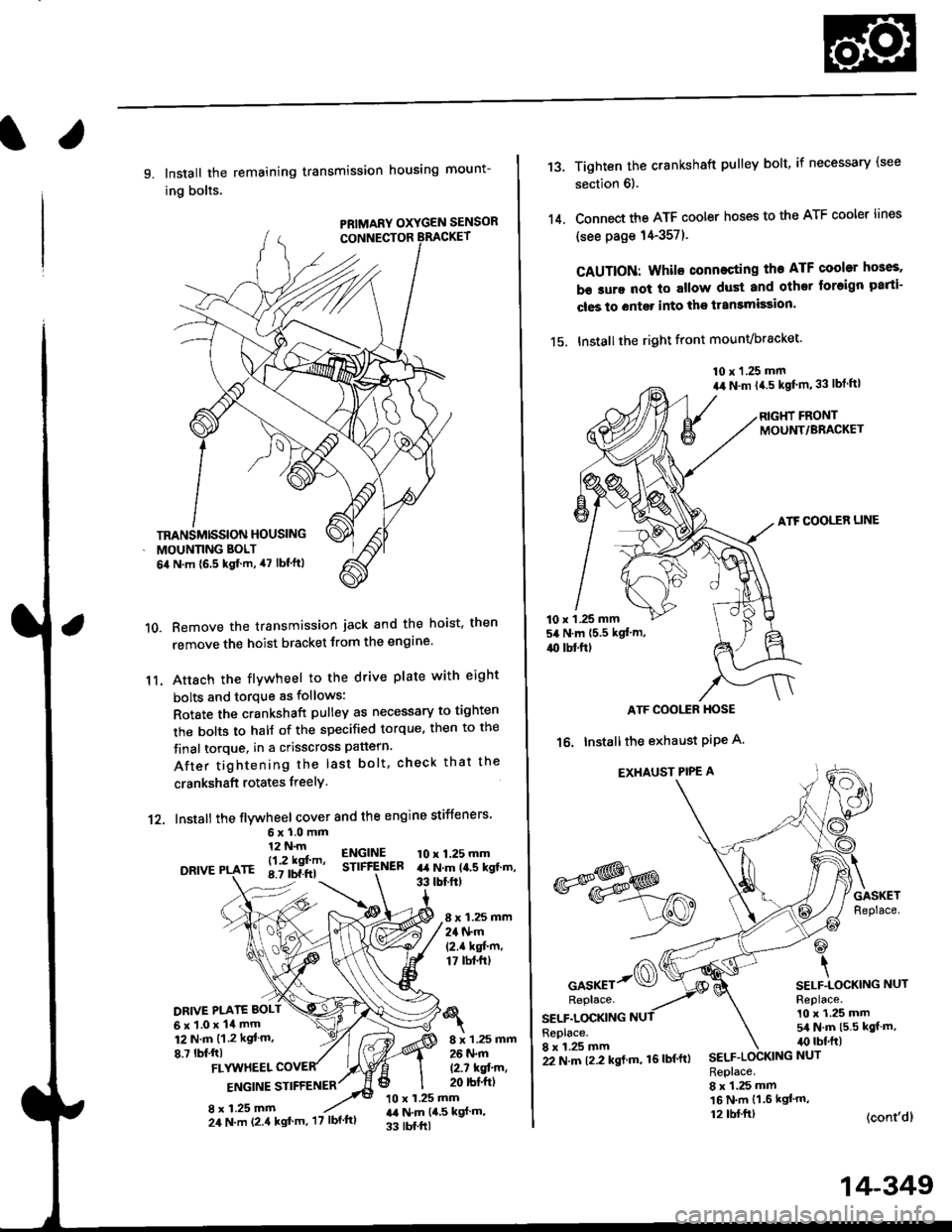
9. Install the remaining transmission housing mount-
ing bolts.
PRIMARY OXYGEN SENSOR
Remove the transmission jack and the hoist. then
remove the hoist bracket from the engine'
Attach the flvwheel to the drive plate with eight
bolts and torque as follows:
Rotate the crankshaft pulley as necessary to tighten
rhe bolts to half of the specified torque, then to the
final torque, in a crisscross pattern.
After tightening the last bolt. check that the
crankshaft rotates freelY.
10.
11.
12. Install the flywheel cover and the engine stiffeners
DRIVE
6xl.0mm12 N.m
- l12 kgf'm'rE 8.7 tbf.ftl
ENGINESTIFfENEB10 x 1.25 mmart N.m la.s kgt.m,33 tbtftt
8 x 1.25 mm24 N.m(2.1 kgf'm,17 tbt.ftt
DRIVE PI.ATE BOLT
6x1.0x14mm12 N.m {1.2 kgt m.
8.7 lbf,ftl8 x 1.25 mm26 N.m
12.7 kqfin,20 rbt'ftlFLYUTHEEL
ENGINE STIFFENER
8 x 1.25 mm10 x 1.25 mmr,a N.m {4,5 kgf m,
33 tbf.ftl
TRANSMISSION HOUSING
MOUNNNG BOLT
6il N.m {6.5 kgf.m, 47 lbf'ftl
24 N.m (2.4 kgt'm, '17 lbf'ftl
22 N.m t2.2 kgl m, 16lbf'ftl
14-349
13.
14.
Tighten the crankshaft pulley bolt, if necessary (see
section 6).
Connect the ATF cooler hoses to the ATF cooler lines
(see page 14-357).
CAUTION: Whilo connecting the ATF cooltr hGes,
b€ sure not lo allow dust and other loreign parti-
cles to entg. into the transmission.
15. Installthe right front mounvbracket'
10 x 1.25 mm
a,r N.m {4.5 kgf'm,33 lbt ftl
RIGHT FRONTMOUNT/BRACKET
ATF COOLER LINE
10 x 1 .25 mm54 N.m {5.5 kgt'm,
4{) tbl.ftt
ATF COOI,TR HOSE
16. Installthe exhaust PiPe A.
EXHAUST PIPE A
GASKETReplace.
@
\SELF.LOCKING NUTReplace.10 x 1.25 mm5/a N.m {5.5 kgt m,irc lbf.ft)
(cont'dl
*s$o
oor*rr-@Replace.
SELF.LOCKINGReplace.8 x 1.25 mmSELF.LOCKING NUT
Replace.8 x 1.25 mm16 N.m {1.6 kgl'm,12 tbl.ftt
Page 1026 of 2189
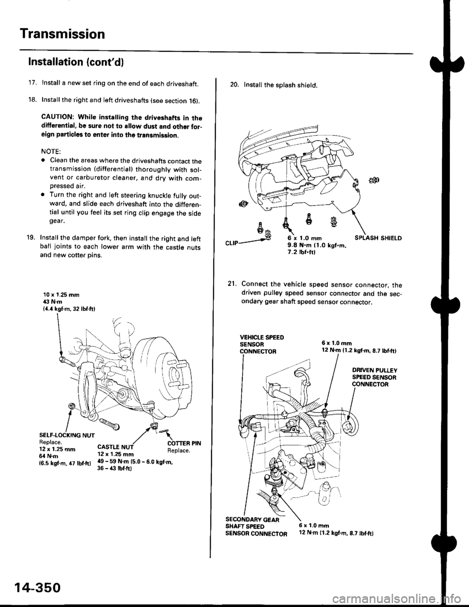
Transmission
17.
Installation (cont'd)
Install I new set ring on the end of each driveshaft.
Install the right and left driveshafts (see section 16).
CAUTION: While instatling the drive3hafts in thedifferential, be sure not to allow dust and olher for-aign particles to enter into tho transmission.
NOTE:
. Clean the areas where the driveshafts contact thetransmission {differential} thoroughly with sol-vent or carburetor cleaner, and drv with com-
Dressed air.
. Turn the right and left steering knuckle fully out-wa.d, and slide each driveshaft into the differen-tial until you feel its set ring clip engage the sidegear.
Install the damper fork, then install the right and leftball joints to each lower arm with the castle outsand new cotter pins.
19.
10 x 1.25 mm43 N.m{4.4 kgf.m, 32 lbf.ftl
SELF-LOCKING NUTReplace.12 x 1.25 mm6l N.m
CASTI.I'12 x 1.25 mm
{6.s ksr.m. 47 tbr.ftr l! _ ll ffiteo
- s.o tet'.,
14-350
20. Install the splash shietd.
aa
I6I6*
"a,a s
21.
SECONOARY GEARSHAFT SPEEDSENSOB CONNECTOR
6 x 1.0 mm9.8 t{.m 11.0 kgt.m,7.2 tbf.trl
Connect the vehicle speed senso. connector. thedriven pulley speed sensor connector and the sec-ondary gear shaft speed sensor connector,
6x1,0mm12 N.m {1.2 kg{.m, 8.7 tbf,ft)
DRIVEN PULLEYSPEED SENSORCONNECTOR
E.
6 x 1.0 m.rl'12 N.m {1.2 kg{.m,8.7 tbf.fo
Page 1036 of 2189
Driveshafts
Inspection
Driveshaft Boot
Check the boots on the driveshaft for cracks, damage,
leaking grease and loose boot bands. lf any damage is
found, replace the boot and boot bands,
Loose Splines
Turn the driveshaft by hand and make sure the splines
and joint are not excessively loose. lf any damage is
found, replace the inboard joint.
Twisied or Cracked
Make sure the driveshaft is not twisted or cracked.
Reolace it if necessarv.
DRIVESHAFT
BOOT BANDS
1.
Removal
Loosen the wheel nuts slightly.
Raise the front of the vehicle, and support it with
safety stands in the proper locations (see section 'l).
Remove the wheel nuts and front wheels.
Drain the transmission fluid (see section 13 or 14).
Raise the locking tab on the spindle nut, then
remove the nut.
Remove the selJ-locking nut and flange bolts.
FLANGE BOLT10 x 1.25 mm
(cont'd)
16-3
1.
Page 1038 of 2189
t
Disassembly
lnboard Joint Side:
1. Carefully clamp the driveshaft in a vise with soft
jaws, then remove the set ring from the inboard
joint.
2. Remove the boot bands. Take care not to damage
the boot.
. lf the boot band is a locking tab type, pry up the
locking tabs with a screwdriver, and raise the
end of the band.
. It the boot band is a welded type, cut the boot
ba nd.
. lf the boot band is a crimping type, pry up the
end of the band with a screwdraver.
. lf the boot band is a double loop type, lift up the
band bend.
Locking Tab Typs
Welded Type
J
Replace.
l,
Crimping Type
Double Loop Type
Mark each roller and inboard joint to identify the
locations of rollers and grooves in the inboard joint.
Then remove the inboard joint on the shop towel.
Be careful not to drop the rollers when separating
them from the inboard ioint.
INBOARD JOINTCheck splines for wear or damage,Check inside bore for wear.Inspect for cracks.
(cont'd)
16-5