Page 1062 of 2189
Steering Gearbox
Removal(cont'd)
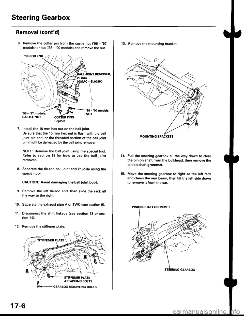
Remove the cotter pin from the castle nut ('96 - '97
models) or nut ('98 - '00 models) and remove the nut.
Installthe 10 mm hex nut on the ball joint.
Be sure that the 10 mm hex nut is flush with the balljoint pin end, or the threaded section of the ball joint
pin might be damaged by the balljoint remover.
NOTE: Remove the ball joint using the special tool,
Refer to section 18 for how to use tho ball joint
remover.
Separate the tie-rod ball joint and knuckle using the
specialtool.
CAUTION: Avoid damaging the ball ioint boot.
Remove the left tie-rod end, then slide the rack all
the way to the right.
Separate the exhaust pipe A or TWC (see section g).
Disconnect the shift linkage (see section 13 or sec-
tion 14).
Remove the stiffener plate.
7.
'10.
11.
12.
Replace.
17-6
13. Remove the mounting bracket,
Pull the steering gearbox all the way down to clear
th€ pinion shaft from the bulkhead, then remove thepinion shaft grommet,
Move the steering gearbox to right so the left rack
end clears the rear beam, then tilt the left side down
to remove it from the car.
t5.
STEENING GEARBOX
PINION SHAFT GROMMET
Page 1063 of 2189
)
Disassembly
'1.
2.
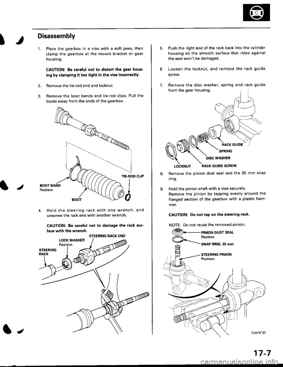
Place the gearbox in a vise with a soft jaws, then
clamp the gearbox at the mount bracket or gear
housing.
CAUTION: Be carcful not to distort the gear hous-
in9 by clamping it too iight in the vise incorrectly.
Remove the tie-rod end and locknut.
Remove the boot bands and tie-rod clips. Pull the
bogts away from the ends of the gearbox.
/
TIE.ROD CLIP
4. Hold the steering rack with one wrench, and
unscrew the rack end with another wrench.
CAUTION: Be caleful not to damagc the rack sur'
facs with the wrench.
STEERING RACK ENO
l,
17-7
7.
Push the right end of the rack back into the cylinder
housing so the smooth surface that rides against
the seal won't be damaged.
Loosen the locknut, and remove the rack guide
screw.
Remove the disc washer, spring and rack guide
from the gear housing.
RACK GUIOE
SPRING
8.
9.
LOCKNUT RACK GUIDE SCREW
Remove the pinion dust seal and the 35 mm snap
nng.
Hold the pinion shatt with a vise securely
Remove the pinion by tapping evenly around the
flanged section of the gearbox with a plastic ham-
met.
CAUTION: Do not tap on tho steering rack.
NOTE| Do not reuse the removed pinion.
9._
ViF=\_
PINION DUST SEALReplace.
SNAP RING,35 mm
STEERING PINIONFeplace.
DISC WASHER
Page 1064 of 2189
Steering Gearbox
Disassembly (cont'dl
10. Slide the steering rack out of the cylinder housing.
CAUTION: Be carelul not to damage the bushing in
the cylinder housing.
11. Remove the rack end bushing.
GEARBOX MOUNTING CUSHION
Inspect inner wall tor wear or damage.
17-8
12. Replace the gearbox mounting cushion if necessary:
. To remove the cushion, use a sharp knife and make
a cut down the length of the cushion. Be careful not
to damage the paint on the outside of the cylinder
housing. Remove the old cushion.. Apply weatherstrip adhesive to the inside of the
new cushion. Install the cushion onto the cylinder
housing and position it 20 - 22 mm (0.79 - 0.87 in)
from the end of the cylinder housing as shown.
NOTE: After installing the cushion, wipe off any
excess adhesive that may have dripped into the
inside of the cylinder housing.
20 - 22 mm 10.79 - 0.87 in)
Page 1065 of 2189
Reassembly
NOTE:
. Clean the disassembled parts with solvent, and dry them with compressed air. Do not dip the rubber parts in solvent.
. Alwavs replace the non reuseable parts with new ones before assembly
. Do not allow dust, dirt, or other foreign materials to enter the steering gearbox.
-6,1
PINION OUST SEALReplace.RACK ENO BUSHING
\
^lr
r@
-6i
GEARBOX MOUNTING CUSHIONS
V."^pR,NG,3smm
tr
a/
^$'q0
")*o''o"'"'*
DISC WASHER
RACK GUIDE
(cont'd)
17-9
tJ
Page 1066 of 2189
Steering Gearbox
Reassembly (cont'dl
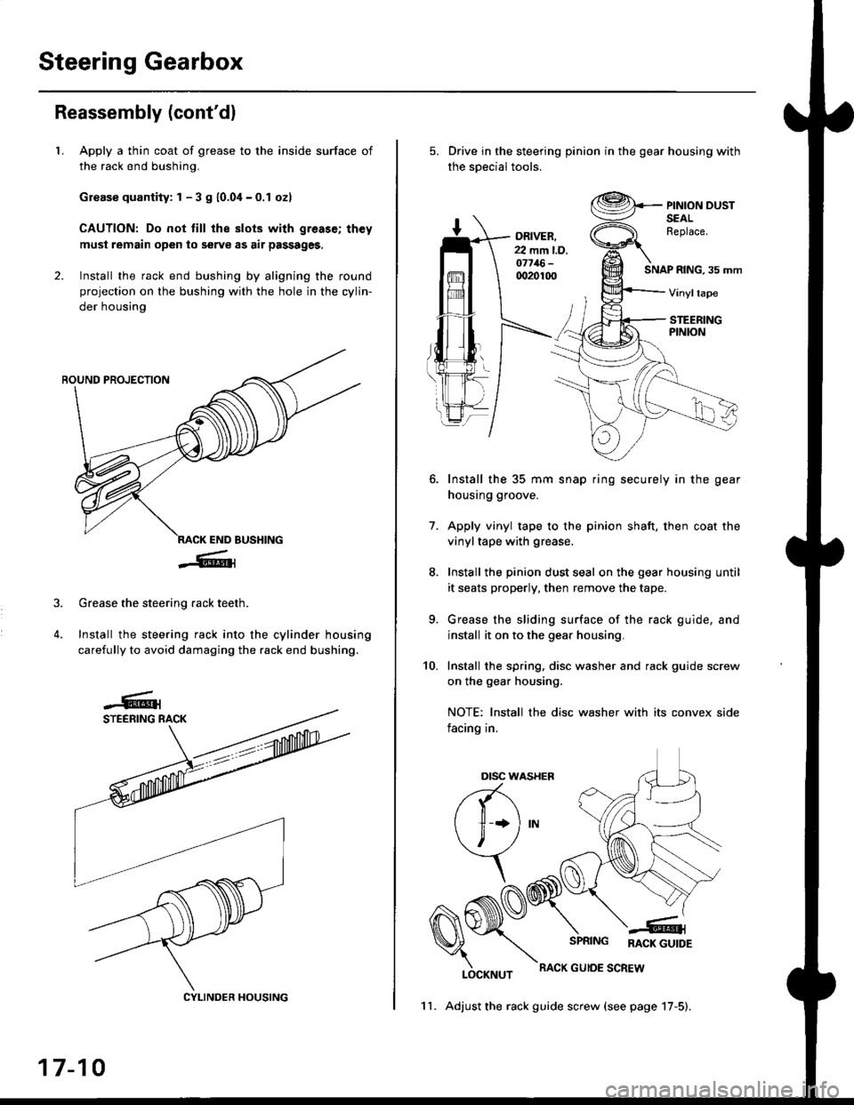
LApply a thin coat of grease to the inside surface of
the rack end bushing.
Grease quantity: 1 - 3 S 10.04-0.1 ozl
CAUTION: Do not till the slots with greas€; th€y
must remain open to serve as air passages,
Install the rack end bushing by aligning the round
projection on the bushing with the hole in the cylin-
der housing
4.
Grease the steering rack teeth.
Install the steering rack into the cylinder housing
carefully to avoid damaging the rack end bushing.
CYLINDER HOUSING
17-10
11. Adjust the rack guide screw (see page 17-5).
Drive in the steering pinion in the gear housing with
the soecial tools.
ORIVER.22 mm l.D.o7716-qr20100SNAP RING, 35 mm
PINION DUSTSEALReplace.
Vinyltape
STEERINGPINION
7.
Install the 35 mm snap ring securely in the gear
housing groove.
Apply vinyl tape to the pinion shaft, then coat the
vinyltape with grease.
Install the pinion dust seal on the gear housing until
it seats properly, then remove the tape.
Grease the sliding surface of the rack guide, and
install it on to the gear housing.
Install the spring, disc washer and rack guide screw
on the gear housing.
NOTE: Install the disc washer with its convex side
facing in.
LOCKNUT
SPRING RACK GUTDE
RACK GUIOE SCREW
10.
Dtsc w,
a(-\
l1 *l
\, ,/
\
Page 1067 of 2189
It
12.
13.
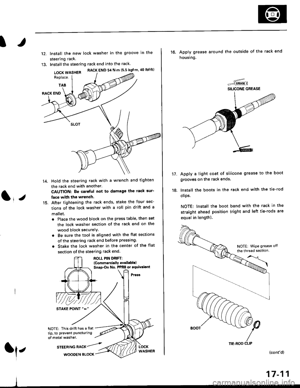
lnstall the new lock washer in the groove in the
steering rack.
Installthe steering rack end into the rack
LOCK WASHER RACK END 54 N m ts.s kgf'm, 40 lbtft)
Replace.
TAB
(l*v
14.
15.
RACK END
Hold the steering rack with a wrench and tighten
the rack end with another.
CAUTION: Be careful not to damage the tack sur-
fac€ with the wrench.
After tightening the rack ends, stake the four sec-
tions of the lock washer with a roll pin drift and a
mallet.
. Place the wood block on the press table. then set
the lock washer section of the rack end on the
wood block securelY.
. Be sure the tool is aligned with the flat sections
of the steering rack end before pressing
. Stake the lock washer in the center of the flat
section of the steering rack end.
ROLL PIN DnlFTl(Commorci.lly .Yril.blolSnap-On No. PPRS or oquival.nt
NOTE: This drift has a flat
tip, to prevent puncturing
of metal washer.
srEEatruG nlCr/rl,WOODEN BLOCK
TIE.ROO CLIP
16. Apply grease around the outside ot the rack end
housing.
Apply a light coat of silicone grease to the boot
grooves on the rack ends.
lnstall the boots in the rack end with the tie-rod
clips.
NOTE: Install the boot band with the rack in the
straight ahead position (right and left tie-rods are
equal in length).
=-..r=-q!q!!.n
SILICONE GREASE
17.
(cont'd)
17-11
NOTE| WiPe grease off
the thread sectlon
Page 1071 of 2189
Component Locations
I
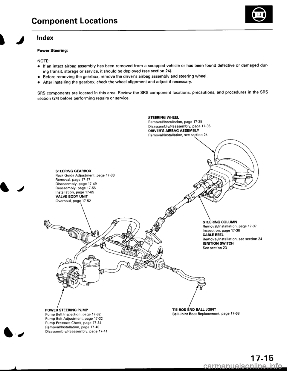
lndex
Power Steering:
NOTE:
. li an intact airbag assembly has been removed trom a scrapped vehicle or has been found defective or damaged dur-
ing transit. storage or service, it should be deployed (see section 24).
. Before removing the gearbox, remove the driver's airbag assembly and steering wheel.
. After installing the gearbox, checkthewheel alignmentand adjust if necessary.
SRS components are located in this area. Review the SRS component locations. precautions, and procedures in the SRS
section {24} before performing repairs or service.
STEERING WHEELRemoval/lnstallation, page 17-35
Disassembly/Feassembly, page 17-36
DRIVER'S AIRBAG ASSEMBLYRemoval/lnstallation, see section 24
STEERING GEAREOXRack Guide Adiustment, page 17'33
/
Removal, page 17 47Disassembly, page 17-49Reassembly, page 17-55Installation, page 17-65VALVE EODY UNITOverhaul, page 17 52
COLUMNFemoval/lnstallation, page 17-37Inspection, page 17-38CASLE REELRemoval/lnstallation, see section 24
IGNITION SWITCHSee section 23
POWEF STEERING PUMPPump Belt Inspection, page 11-32Pump Belt Adiustmenl, page 11'32Pump Pressure Check, page 17 34Removal/lnstallation, page 17'40Disassembly/Reassembly, page 17-41
TIE.ROD END BALL JOINTBallJoint Boot Replacement, page 17-68
1,,
17-15
Page 1078 of 2189
Troubleshooting
General Troubleshooting
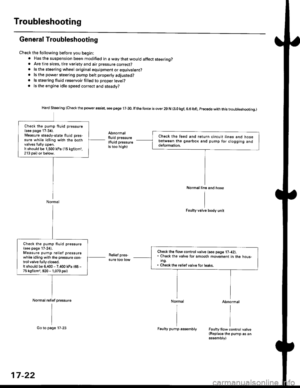
Check the following before you begin:. Has the suspension been modified in a way that would affect steering?. Are tire sizes, tire variety and air pressure correct?. lsthe steering wheel original equipment or equivalent?. lsthe powersteering pump belt properlyadiusted?
. ls steeringfluid reservoirfilledto proper level?. ls the engine idle speed correct and steady?
Hard Steering (Check the powor assist. se€ page 17-3o. lfthe torce is over 29 N (3.0 kgf, 6.6lbo, Procede with this troubleshootinq.)
Abnormallluid pressure
{fluid pressureis too high)
Faulty valve body unit
Relief pres-sure too low
Abnormal
Faulty llow control valve(Replace the pump es anassembly)
Ch€ck the feed snd return circuit lin€s ano nosebetw6€n the gearbox and pump for clogging andd€lormation.
Normal line and hose
Check the pump fluid pressure(soe page 17-34).l/easure steady-state tluid pres-s!re while idling with the bothvalves tully open.It should be 1.500 kPa (15 kgf/cmr,213 psi) or below.
Normal
Check th€ flow control vslve (see page 17-42).. Chock the valvo lor smooth movement in the hous-ing.. Check the reliefvalve for leaks.
Check the pump fluid pressure
{see page 17-34).Measure pump relief pressurewhile idling with the pressure con-trol valve Iully closed.It should be 6,400 - 7,400 kPa (65 -
75 kgflcm,,920 - 1,070 psi)
Normal relisf pressure
17-22
Go to page 17-23Faulty pump assembly