Page 797 of 2189

Pressure Testing
@I While testing, be caroful of th€ rotating front wheels.
. Make sure lifts, iacks, and satoty stands are placod properly (see section 1)'
CAUTION:
. Beforo iesting, be sure the transmission fluid is tilled to tho proper level'
. Warm up tho engine before testing'
1. Raise the vehicle (see section 1).
2. Warm up the engine, then stop the engine and connect a tachometer'
3. Connect the oil pressure gauges to each inspection hole.
TOROUE: 18 N.m (1.8 kgf'm, 13 lbnft)
cAUTloN: connact the oil pressuro gauges securely; be suro not to allow dust and other foreign Parlicles to entel
the inspestion holos'
A/T OIL PRESSURE GAUGESET w/PANEL07t06 - 0020400
A/T LOW PRESSURE GAUGE
SET WPANEL07406 - 0070300
A/T OIL PRESSURE HOSEADAPTER07Mru - PY0120(4 requiJedl
A/T OIL PBESSURE HOSE
2210 mmOTMAJ - PY4{)llA
14 roquircdl
Start the engine, and measure the respective ptessure as follows'
a Line Pressure
. 1st Clutch Pressure
. 2nd,3rd and 4th Clutch Pressure
Install a new washer and the sealing bolt in the inspection hole. and tighten to the specified torque'
TOROUE: l8 N.m (1.8 kgf'm,13lbf'ft)
NOTE: Do not reuse old sealing washers; always replace washers'
(cont'd)
14-119
Page 803 of 2189
19. Remove the engine stiffener and the torque con-
verter cover.
Remove the eight drive plate bolts one at a tlme
while rotating the crankshaft pulley.
Remove the distributor.
Attach a hoisting bracket to the engine, then lift the
engine slightly.
HOISTBRACKET
20.
21.
COVER
23. Place a jack under the transmission. and ra6a :'.
transmission iust enough to take weight otf ol tF.
mounts. then remove the transmission mounl
TRANSMISSIONMOUNT BRACKET
Remove the transmission housing mounting bolts
and the rear engine mounting bolts.
Pull the transmission away from the engine until it
clears the 14 mm dowel pins, then lower it on the
transmission jack.
TRANSMISSION HOUSING
lf necessary, remove the torque converter anc:"
starter motor.
24.
25.
1+16
Page 805 of 2189

O ROLLER
O COLLAR
O o-RING Replace.
@ FEED PIPE FLANGE
@ O-RING Replace.
@ SNAP RING
€) 3RD CLUTCH FEED PIPE
€) COUNTERSHAFT LOCKNUT (FLANGE NUT)
23 x 1.25 mm Replace.
o coNlcAL SPRING WASHER Replace.
@ PARK GEAR
@ ONE.WAY CLUTCH
@ COUNTERSHAFT lST GEAR
@ NEEDLE BEARING
@ COUNTERSHAFT lST GEAR COLLAR
@ o-RlNGs Replace.
@ END covER GASKET Replace.
E) DOWEL PINS
@ PARK PAWL STOP
@ LocK WASHER Replace.
@ PARK STOP Selective part
€D PARK LEVER
@ PARK LEVER SPRING
€D DRAIN PLUG
€) SEALING WASHER Replace
@ o-RING Replace.
@ COUNTERSHAFT SPEED SENSOR
@) PARK PAWL
@ PARK PAWL SPRING
@ PARK PAWL SHAFT
@ LINEAR SOLENOID ASSEMBLY
@ LINEAR SOLENOID GASKET REPIACE.
@) END COVER
@ lsT CLUTCH FEED PIPE
@ O-RINGS Replace.
@ FEED PIPE FLANGE
C) SNAP BING
@ MAINSHAFT LOCKNUT (FLANGE NUTI 21 x 1 25 mm
Replace.
@ CONICAL SPRING WASHER RePlace
@) lST CLUTCH ASSEMBLY
@ o-RlNGs Replace.
€) THRUST WASHER
@) THRUST NEEDLE BEARING
@ NEEDLE BEARING
@ MAINSHAFT lST GEAR
@ MAINSHAFT lST GEAR COLLAR
@) ATF COOLER LINE
@ SEAUNG WASHERS Replace.
@ LINE BOLT
@ ATF DIFSTICK
@ ATF COOLER LINE
@ UNE BOLT
@ SEALING WASHERS Replace.
@ VEHICTT SPEED SENSOR
@ O-RING Replace.
TOROUE SPECIFICATIONS
Bolt/Nut No.Torque ValueSizeRemarks
6B
8F
12A.'l8D
2'tM
23C
'12 N'm (1.2 kgim,8.7 lbift)
14 N.m (1.4 kgf.m, 10 lbf'ft)
22 N.m (2.2 kgf.m, 16 lbf'ft)
28 N.m (2.9 kgf.m, 21 lbf'ft)
49 N.m (5.0 kgf.m, 36 lbf'ft)
78 N.m (8.0 kgf'm, 58 lbf'ft)
103 N.m {10.5 kgf'm,75.9 lbift)
6x1.0mm
6x1.0mm
8 x 1,25 mm
12 x 1.25 mm
18 x 1.5 mm
21 x 1.25 mm
23 x 1.25 mm
Line bolt
Drain plug
Mainshatt locknut: Left-hand threads
Countershaft locknut:
Left-hand threads
14-127
Page 809 of 2189

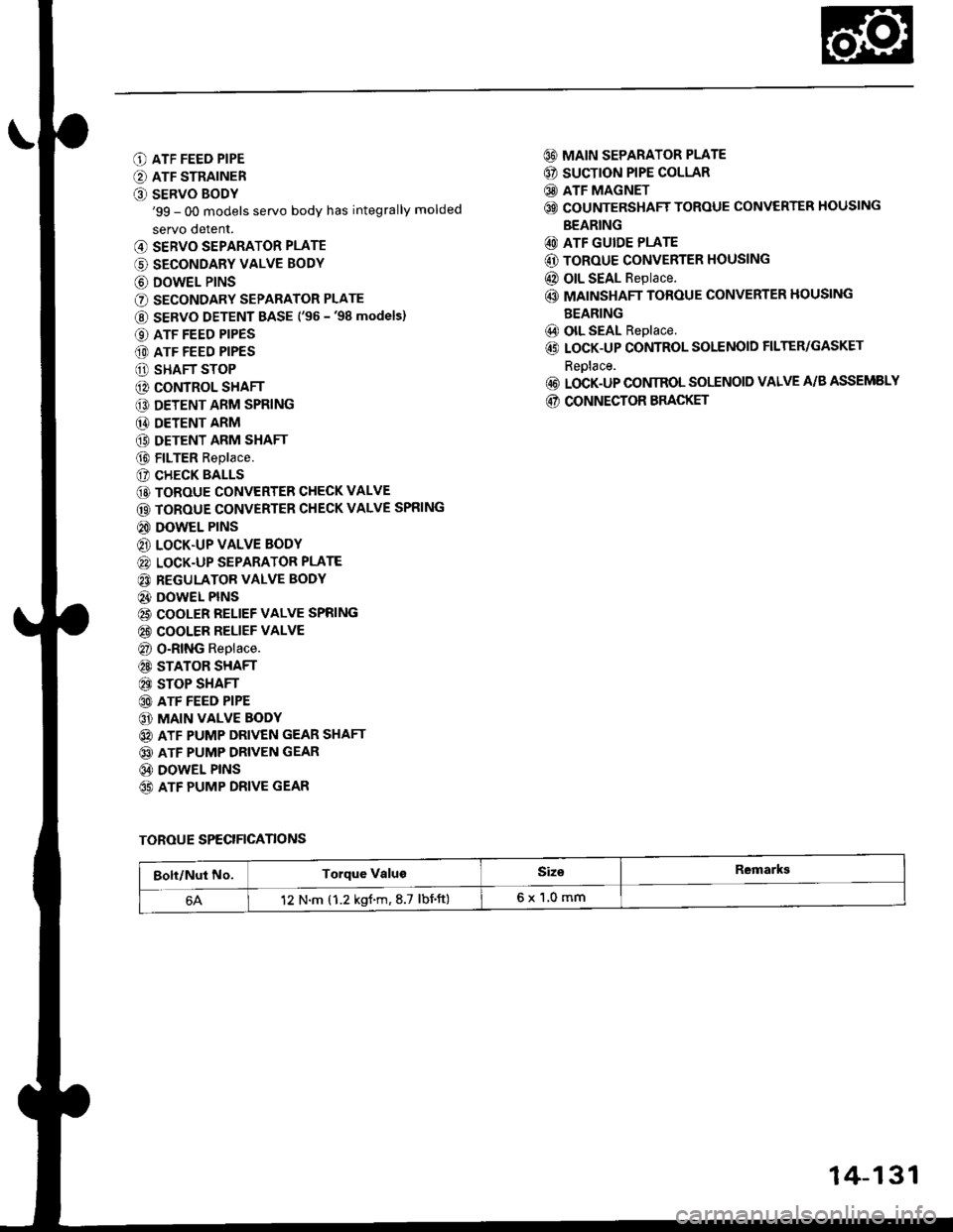
O ATF FEED PIPE
O ATF STRAINER
O SERVO BODY'99 - 00 models servo body has integrally molded
servo detent.
@ SERVO SEPARATOR PLATE
(' SECONDARY VALVE BODY
@ DOWEL P|NS
O SECONDARY SEPARATOR PLATE
@ SERVO DETENT BASE ('�96 -'98 models)
O ATF FEED PIPES
(D ATF FEED PIPES
O SHAFT STOP
@ CONTROL SHAFT
€D DETENT ARM SPRING
@ DETENT ARM
(9 DETENT ARM SHAFT
@ FILTER Replace.
(? CHECK BALLS
@ TOROUE CONVERTER CHECK VALVE
@ TOROUE CONVERTER CHECK VALVE SPRING
@ DOWEL PINS
@ LOCK.UP VALVE BODY
@ LOCK-UP SEPARATOR PLATE
@ REGULATOR VALVE BODY
@} DOWEL PINS
@ COOLER RELIEF VALVE SPRING
@ COOLER RELIEF VALVE
@ O-RING Replace.
@ STATOR SHAFT
@ STOP SHAFT
@ ATF FEED PIPE
@ MAIN VALVE BODY
@ ATF PUMP DRIVEN GEAR SHAFT
@ ATF PUMP DRIVEN GEAR
@ DOWEL PINS
65) ATF PUMP DRIVE GEAR
@ MAIN SEPARATOR PLATE
@ SUCTION PIPE COLLAR
@ ATF MAGNET
@ COUNTERSHAFT TOROUE CONVERTER HOUSING
BEARING
@ ATF GUIDE PLATE
@ ToRoUE CONVERTER HOUSING
@ OIL SEAL Replace.
@ MAINSHAFT TOROUE CONVERTER HOUSING
BEARING
@) olL SEAL Replace.
@ LOCK-UP CONTROL SOLENOID FILTER/GASKET
Reolace.
@ LOCK-UP CONIROL SOLENOID VALVE A/B ASSEMELY
@ CONNECTOR BRACKET
TOROUE SPECIFICANONS
Bolt/Nut No.Torque ValugSiz€Remarkg
12 N.m (1.2 kgf.m,8.7 lbnft)6x1,0mm
14-131
Page 823 of 2189

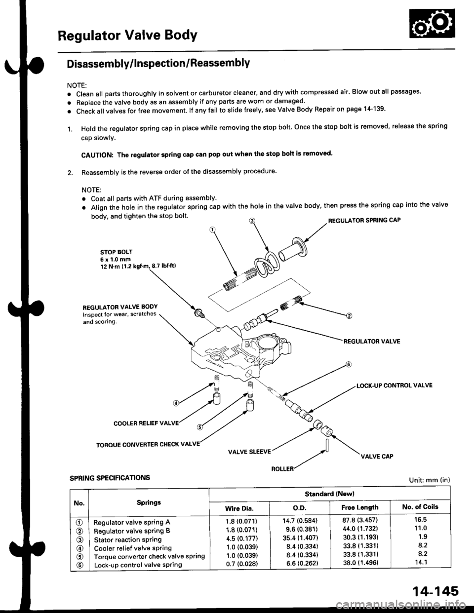
Regulator Valve Body
Disassembly/lnspection/Reassembly
NOTE:
. cleanall parts thoroughly in solvent or carburetor cleaner, and drywith compressed air. Blowoutall passages
. Replace the valve body as an assembly if any parts are worn or damaged.
. check allvalves for free movement. lf anyfail toslidetreely, see valve Body Repairon page 1+139.
1. Hold the regulator spring cap in place while removing the stop bolt. once the stop bolt is removed. release the spring
cap slowly.
CAUTION: The regulator 3pring cap can pop out when the stop boh is removod'
2. Reassembly is the reverse order ofths disassembly procedure.
NOTE:
o Coat all parts with ATF during assembly.
. Align the hole in the regulator spring cap with the hole in the valve body, then press the spring cap into the valve
body, and tighten the stop bolt.
STOP BOLT6x1.0mm12 N.m 11.28.7 tbf.lrl
^/^'ou*'oRsPRrNGcAP
*N@
REGULATOR VALVE
\=f -.-*
*fi /F { a-tLocK.uPcoNrRoLvALVE
cooLERRELlEFvALVr"r?
ry
roRouE coNvERrER cHEcKv ^LvE//
v ^r* "r**::f vi{LvE cAp
SPRING SPECIFICANONS
REGULATOR VALVE BODY
Inspect lor wear, scratches
and scorlng.
Unit: mm (in)
No,Springe
Standard (Now)
Wire Dia.o.D.Free LengrthNo. of Coils
o
o
@
@
@
Regulator valve sPring A
Regulator valve spring B
Stator reaction spring
Cooler relief valve spring
Torque converter check valve spring
Lock-up control valve sPring
1.8 {0.07'�r)
1.8 (0.071)
4.5 (0.177)
1.0 (0.039)
1.0 (0.039)
0.7 (0.028)
'r4.7 (0.584)
9.6 (0.381)
35.4 (1.407)
8.4 {0.334)
8.4 {0.334}
6.6 {0.262}
87.8 (3.457)
44.0 (1.732)
30.3 (1.193)
33.8 (1.331)
33.811.3311
38.0 {1.4961
11.0
1.9
8.2
a.2't 4.1
14-145
Page 846 of 2189

Differential
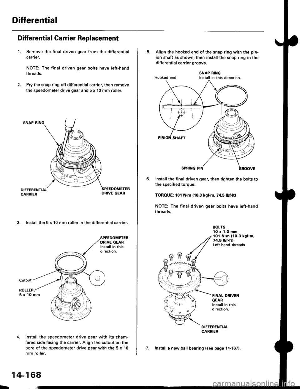
Diff erential Carrier Replacement
L Remove the final driven gear from the differential
carrier.
NOTE: The final driven gear bolts have left-hand
threads.
Pry the snap ring off differential carrier, then remove
the speedometer drive gear and 5 x 10 mm roller.
SNAP RING
3. Install the 5 x l0 mm roller in the differential carrier,
Install the speedometer drive gear with its cham-
fered side facing the carrier. Align the cutout on the
bore of the speedometer drive gear with the 5 x 10
mm roller.
L
14-168,
5. Align the hooked end of the snap ring with the pin-
ion shaft as shown, then install the snap ring in the
differential carrier groovs.
SNAP RINGHooked end Install in this direction.
SPNI G PIN
Install the final driven gear, then tighten the bolts to
the specified torque.
TOROUE: 101 N.m (10.3 kgf'm, 74.5 lbf.ftl
NOTE: The final driven gear bolts have left-hand
threads.
BOLTS10 r 1.O mm1Ol t{.m 11O.3 kgf.m,74.5 lbl.frlLeft-hand rhreads
FINAL DRIVENGEARlnstall in thisdirection.
DIFFERENTIALCARRIER
7. Install a new ball bearing (se€ page 14-157).
Install in this direclon.
Page 847 of 2189
OilSealRemoval
1. Remov€ the differential assembly.
2, Remove the oil seal from the transmission housing,
OIL SEALRoplace.
the oil seal from ths torque converterRemove
housing.
OIL SEALReplace.
TOROUE CONVERTEFHOUSING
Oil Seal Installation/Side Glearance
1. Install a 2.50 mm (0.098 in) set ring,80 mm in trans-
mission housing.
NOTE: Do not install the oil seal vet.
RING, 80 mm
TRAITISMISSlONHOUS|l{G
Install the differential assembly into the torque con-
verter housing using the specialtool as shown.
Install the transmission housing and tighten the
bolts {see page 14-178 and 14-179).
{cont'd)
14-169
Page 855 of 2189

1.Install the ATF magnet and suction pipe collar in the
torque converter housing. if necessary.
lnstall the main seDarator plate and the two dowel
pins on the torque converter housang.
Install the ATF pump drive gear, ATF pump driven
gear and ATF pump driven gear shaft on the torque
converter housing.
NOTE; Install the ATF pump driven gear with its
grooved and chamfered side tacing down.
ATF PUMP
ATF PUMP DRIVENGEAR SHAFT
ATF PUMPDRIVEN GEAR
Grooved and chamferedside taces separalorplate.MAIN SEPARATORPLATE
4.Loosely install the main valve body with five bolts.
Make sure the ATF pump drive gear rotates smoothly
in the normal operating direction and the ATF pump
driven gear shaft moves smoothly in the axial and
normal operating directions.
Install the secondary valve body, separator plate
and two dowel pins on the main valve body.
NOTE: Do not installthe bolts.
6. Install the control shaft in the housing with the con-
trol shaft and manual valve together.
7. lnstall the detent arm and arm shaft in the main
valve body, then hook the detent arm spring to the
detent arm,
SERVO SEPARATOR PLATE
DETENT
MANUAL VALVE
DETENT ARM SPRING
15.
14-177
a
10.
11.
Install the servo body and separator plate on the
secondary valve body ('95 - 98 models: seven bolts.'99 - 00 models: eight boltsl.
For '96 - 98 models: Install the servo detent base
and the ATF strainer (two boltsl.
For'99 - 00 models: Install the ATF strainer (one
bolt).
Tighten the five bolts on the main valve body to 12
N.m ('1.2 kgf.m,8.7 lbf.ft).
Make sure the ATF pump drive gear and ATF pump
driven gear shaft move smoothlY'
lf the ATF pump drive gsar and ATF pump driven
gear shaft do not move freely, loosen ths five bolts
on the main valve body, and disassemble the valve
bodies.
Realign the ATF pump driven gear shaft and reassem-
ble the valve bodies, then retighten the bolts to the
specified torque,
CAUTION: Fsilule to align tho ATF pump driven
goar shaft corr.ctly will rscuh in a s€ized ATF pump
drive goar or ATF pump d ven gear shaft.
Install the stator shaft and stop shaft.
Install the bolts and the shaft stop on the secondary
valve body, then tighten the bolts (three boltsl.
Install the torque converter check valve, cooler relief
valve and valve springs in the regulator valve body.
then install the regulator valve body on the main
valve bodv (one bolt).
Install the lock-up valve body on the regulator valve
bodv (seven bolts).
Install the ATF feed pipes in the main valve bodY,
the three ATF feed pipes in the secondary valve and
the four ATF feed pipes in the servo body. (cont'dl
12.
't 3.
14.
PUMP