Page 2 of 2189

INTRODUCTION
How to Use This Manual
This manual contains information for the 1996 - 2000 ClVlC. lt is
divided into 24 sections. The first page of each section is marked
with a black tab that lines up with its corresponding thumb index
tab on this page and the back cover. You can quicklY find the first
page of each section without looking through a tull table ol con_
tents. The symbols printed at the top corner of each page can also
be used as a quick reference system.
Each section includesl
1. A table of contents, or an exploded view index showing:
. Parts disassemblY sequence.
. Bolt torques and thread sizes.
. Page references to descriptaons in text
2. Disassembly/assembly procedures and tools.
3. Inspection.
4. Testing/troubleshooting.
5. Repair.
6. Adjustments.
Special Information
!@ Indicates a sttong possibility of sover. perconal iniurY
or loss ol lite if in3tructions are not follow€d.
GAUTION: Indicaiqs a possibility ot p€lsonal injury or 6quipm.nt
damage il instiuc'tions are not followod
t Noncali-. pu.po.. ot thes6 messages is to help provent demage lo lhe
vehicle, other property, or the €nvironment.
NOTE: Gives helpful information.
CAUTfON: Detaifed descriptions ol standard workshop p.oceduro3.
safoty principles and servico operations are not included. Pleaso
note that this manual contain3 wetnings and cautions against
some sp6cific sGrvic€ methods which could cause PERSONAL
INJURY, damage a vohicle or make il unsafe. Ploase undorstand
that these warnings cannot covsr all conceivable weys in which
service. whelher or not iocommgndod bY HONDA. mighi bo done,
or ol tho possiblG hazardou3 consgquonces of ev€aY conceivablg
way, nor could HONDA invqstigato all 3uch way3. AnYono using
sgrvice procedures or lools, whethei or nol rGcommendod bY
HONDA, must srtisty hifisetf thoroughlylhat nohher pefsonal sefety
nor vehiclc satsty will be reopardi2ed.
All intormation contained in this manual is based on the latest prod
uct information available at the time oI printing We reserve the
right to make changes at any time without notice No part of this
publication may be reproduced, stored in retrieval system, or trans'
mitted, in any form by any means, electronic, mechanical, photo
copying, recording, or otherwise, without the prior written permis-
sion of the publisher. This includes text, figures and tables.
*Transaxle
ds
First Edition 8/99 1848 PagesAll Right Reserved
HONOA MOTOR CO., LTD.
Sorvico Publication Offico
As sections with * include SRS components;
sDecial precautions are lequired when servlclng
*Electrical't
*SRSSRS
Page 106 of 2189
Engine RemovaUlnstallation
Installation
Brackei Bolts Torque Specifications:
Dl5Y5, Dl6Y7, Dl6Y8 €nginss
D16Y5, D16Y8 engines (M/Tl:
REAR STIFFENER
8 x 1.25 mm2/t N.m 12.4 kgf.m, 17 tbf.ftl
EXCEPT D16Y5, Dl6Yg engines lM/T)jSTIFFENERTighten the bolts on the stiffenerin the numbered sequence as shown
10 x 1.25 mm44 N.m 14.5 kgf.m,33 tbf.frt
O8x1.25mm24 N.m {2.4 kg{.m,17 tbr.ftt
10 x 1.25 mm14 N.m 14.5 kgt m,33 tbf.ft)
10 x 1.25 mm44 N.m {4.5 kgt m,33 tbr.ftl
10 x 1.25 mm54 N.m {5.5 kgf.m,40 rbf.ftl
10 x 1.25 mm44 N.m {4.5 kg'f.m,33 tbtftlALTERNATOFBRACKET
li) o).
l3l 10 x 1.25 mm44 N.m {1.5 kgt.m,33 tbt.ft)8 x 1.25 mm24 N.m (2.4 kgf.m,17 tbf.ft)
o16Ys, D16Y8enginoslM/T):FRONTSTIFFENER
10 x 1.25 mm4,4 N.m {4.5 kg{.m.33 tbf.ftl8 x 1.25 mm2{ N.m (2.t kgtm,17 rbtft)
10 x 1.25 mm14 N.m (4.5 kgf.m,33 lbf.ftl
5-12
Page 123 of 2189

Valve Clearance
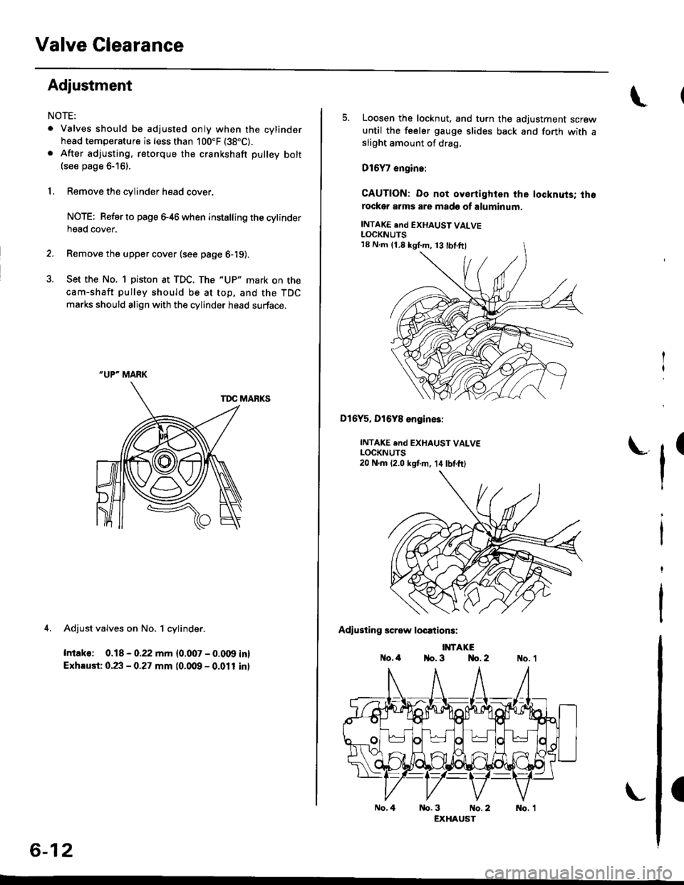
Adjustment
NOTE:
. Valves should be adjusted only when the cylindsrhead temperature is less than 100"F (38"C).
. After adjusting, retorque the crankshaft pulley bolt(see page 6-16).
1, Remove the cylinder head cover.
NOTE; Refer to page e46 when installing the cytinderhead cover.
2. Remove the upper cover (see page 6-19).
3. Set the No. 1 piston at TDC. The "UP" mark on the
cam-shaft pulley should be at top, and the TDC
marks should align with the cylinder head surface.
TDC MARKS
4. Adjust valves on No, 1 cylinder.
Intako: 0.18 - 0.22 mm {0.007 - 0.009 in}
Exhaust: 0.23 - 0.27 mm (0.009 - 0.011 inl
"UP" MARK
6-12
No.4
5. Loosen the locknut, and turn the adjustment screwuntil the feeler gauge slides back and forth with asliOht amount of drag,
D16Y7 engin.:
CAUTION: Do not oyertighlen the locknuts; thorockor arms are made of aluminum.
INTAKE end EXHAUST VALVELOCKNUTS
Dl6Y5, Dl6Y8 engin€3:
INTAKE .nd EXHAUST VALVELOCKNUTS20 N.m 12.0 kstm, 14lbtft)
Adiusting screw locations:
IMTAKEo.4 1{o. 3 No. 2
tr'
(
nb.3 No.2 No. 1EXHAUST
18 N.m (1.8 kgI.m, 13 tbl.ftl
Page 127 of 2189
Crankshaft Pulley and Pulley Bolt
Replacement
When installing and tightening the pulley. follow theprocedure below,
Clean, remove any oil, and lubricate points shown
below.
O: Clean
x: Bemove any oil
a: Lubricate
TIMING BELTGUIOE PLATE
Crankhaft pulley bolt size and torque value:
14 x 1.25 mm
20 N.m {2.0 kgl.m, 14 lbf.ft) + 90'
NOTE: Do not use an impact wrench when installing.
HOI.I'ER HANDTI07JAB - 001020A
HOLDER ATTACHMENT. 50 mm07NAB - ootoilllA
S(rc(ET, 17 mm07JAA-lxtl010A or{Co.nm.rci.lly .v.il.bl.}
CRANKSHAFT
6-16
'1.Tighten the pulley bolt to the specified torque.
Torque: 20 N.m {2.0 kgf.m, 14 lbf'ft}
Use I felt tip pen to mark the pulley bolt head andwasher.
EMBOSSING MARKS
3. Tighten the pulley bolt an additional 90".
EMBOSSING MABKMARKING
\
MARKING
MARKING
I
Page 129 of 2189

Timing Belt
Inspection
1.
2.
3.
Remove the cylinder head cover.
. Refer to page 6 46 when installing.
Remove the upper cover (see page 6 19).
Inspect the timing belt for cracks and oil or coolantsoakrng.
NOTE:
. Replace the belt if oil or coolant soaKeo.. Remove any oil or solvent that gets on the belt.
Rotate pulleyand inspect belt.
After inspecting, retorque the crankshaft pullev bolt{see page 6- 16).
o- I6
Tension Adjustment
CAUTION: lt*ays aa;j"t the timing bett rension withthe engine cold.
NOTE:
. The tensioner is spring loaded to apply tension to thebelt automatically after making the following adjustment.
. Always rotate the crankshaft counterclockwise whenviewed from the pulley side. Rotating it clockwisemay result in improper adjustment of the belt ten-sion.
. lnspect the timing belt before adjusting the belt ten-ston.
1.Remove the cylinder head cover.
. Refer to page 6,46 when installing.
Remove the upper cover (see page 6,'19).
Rotate the crankshaft five or six revolutions to setthe belt.
Set the No. 'l piston at TDC (see page 6-21).
Loosen the adjusting bolt 180'.
2.
3.
4.
5.
\I
ADJUSTING BOLT44 N.m {4.5 kgt m,33 rbf.ft)
7.
8.
Rotate the crankshaft counterclockwise three teethon the camshaft pulley.
Tighten the adjusting bolt.
After inspecting, retorque the crankshaft pulley bolt(see page 6-16).
Page 157 of 2189

Cylinder Head
Installation (cont'dl
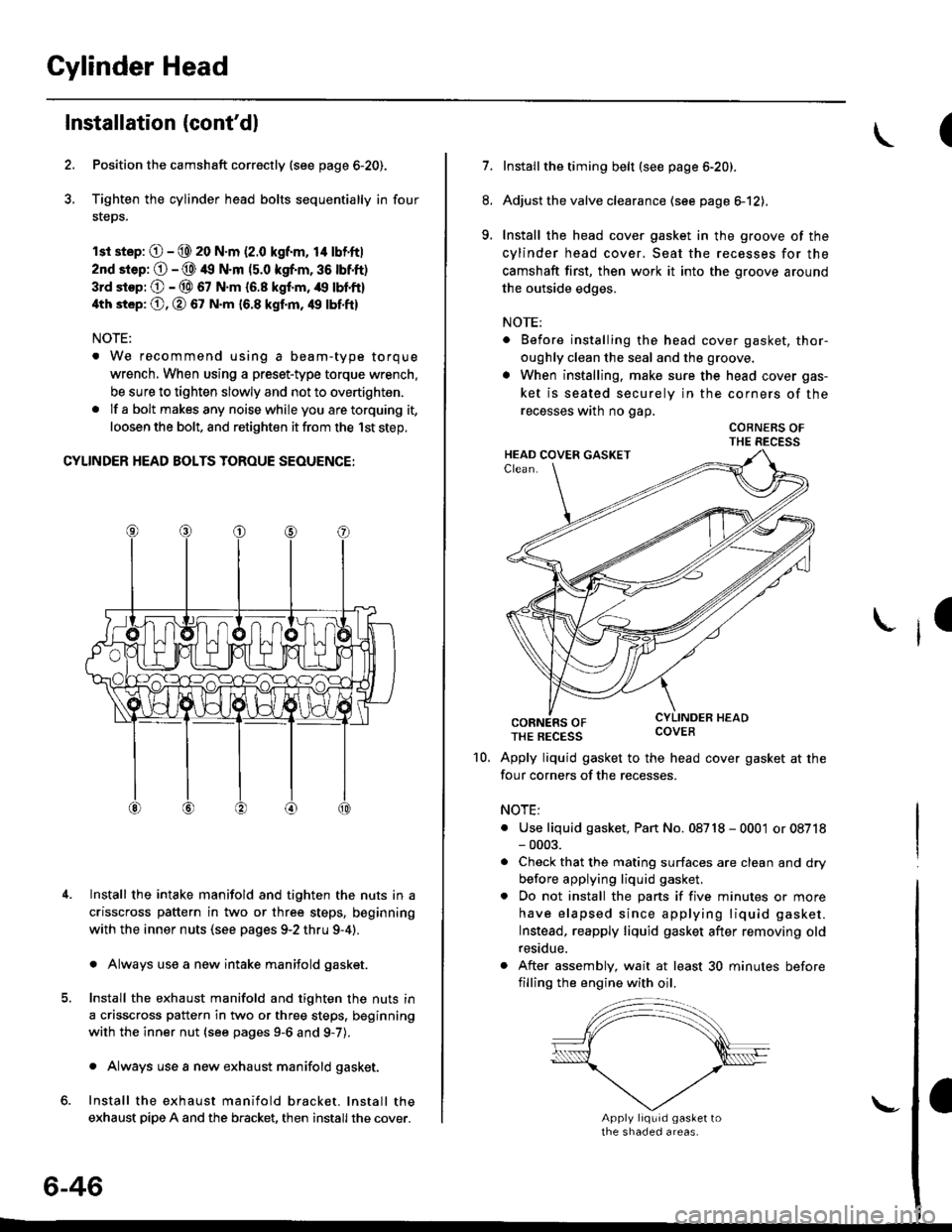
Position the camshaft correctly (see page 6-20).
Tighten the cylinder head bolts sequentially in four
steps.
rsr st.p: O - @ 20 N.m (2.0 kgf.m, 14 lbf'ft|
2nd srep: O - @ 49 N.m (5.0 kgf.m, 36 tbtft)
3rd stop; O - @ 67 N.m {6.8 kgf.m, /r9 lbl'ft}
4th st6p: O, O 67 N.m 16.8 kgf.m, 49 tbf.ftl
NOTE:
. We recommend using a beam-type torque
wrench, When using a preset-type torque wrench.
be sure to tighten slowly and not to overtighten.
. If a bolt makesany noisewhileyou aretorquing it,
loosen the bolt, and retighten it from the 1st step,
CYLINDER HEAD BOLTS TOROUE SEOUENCE:
Install the intake manifold and tighten the nuts in a
crisscross pattern in two or three steps, beginning
with the inner nuts (see pages 9-2 thru 9-4).
. Always use a new intake manifold gasket.
Install the exhaust manifold and tighten the nuts in
a crisscross pattern in two or three steps, beginning
with the inner nut {see pages 9-6 and g-7).
. Always use a new exhaust manifold gasket.
Install the exhaust manifold bracket. lnstall the
exhaust pipe A and the bracket, then install the cover.
4.
6-46
\-
(
7.Installthe timing belt (see page 6-20).
Adjust the valve clearance (see page el2),
Install the head cover gasket in the groove of the
cylinder head cover, Seat the recesses for the
camshaft first, then work it into the groove around
the outside edges.
NOTE:
. Before installing the head cover gasket, thor-
oughly clean the seal and the groove.
. When installing, make sure the head cover gas-
ket is seated securely in the corners of the
recesses wath no gap.
COBNERS OFTHE RECESS
CORNERS OFTHE REcEss covEB
Apply liquid gasket to the head cover gasket at the
four corners of the recesses.
NOTE:
. Use liquid gasket, Pan No. 08718 - 0001 or 08718- 0003.
. Check that the mating surfaces are clean and dry
before applying liquid gasket.
. Do not install the parts if five minutes or more
have elapsed since applying liquid gasket.
Instead, reapply liquid gasket after removing old
residue.
. After assembly, wait at least 30 minutes before
filling the engine with oil.
8.
9.
I
10.
Page 167 of 2189

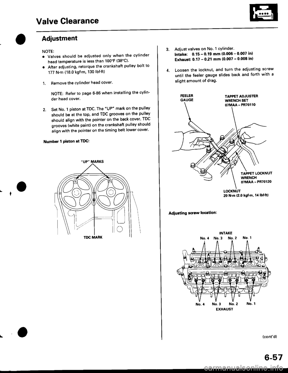
Valve Glearance
Adjustment
NOTE:
. Valves should be adjusted only when the cylinder
head temperaturs is less than 100'F (38'C)'
. After adjusting, retorque the crankshaft pulley bolt to
177 N.m (18.0 kgf'm, 130 lbt'ft)
1. Remove the cylinder head cover'
NOTE: Refer to page G86 when installing the cylin-
der head cover.
2. Set No. 1 pi$on at TDC. The "UP" mark on the pullsy
should be at the top, and TDC grooves on the pulley
should align with the pointer on the back cover' TDC
grooves {white paint) on the crankshaft pulley should
align with the pointer on the timing belt lower cover'
Number I Piston at TDC:
4.
Adjust valves on No. 1 cylinder.
lntako: 0.15 - 0.19 mm {0'006 - 0.007 in)
ExhaGt 0.17 - 0.21 mm {0'007 - 0 008 inl
Loosen the locknut, and turn the adjusting screw
until the feeler gauge slides back and forth with a
slight amount of drag.
TAPPET ADJUSTERWFENCH SET07MM - PR70110
TAPPET LOCKNUTWRENCH07MAA - PR70120
Adiusting sclaw location:
LOCKNUT20 N.m {2.0 kgf'm, lil lbt'ftl
(cont'd)
6-57
Page 169 of 2189
Crankshaft PulleY and PulleY Bolt
Replacement
When installing and tightening the pulley, follow the procedure below'
Clean, remove any oil, and lubricate points shown below
a: Cleanx : Bemove anY oll
a: Lubricate
PULLEY BOLT
WASHER TIMIIGUID
Crankshaft pulley bolt size and torque value:
14 x 1.25 mm
177 N.m t18.0 kgtm, 130 lbf'ftl
NOTE: Do not use an impact wrench when installing'
XX
XXxx
Ii
x
XXXXXX
BELTGUIOE PLATE
PULLEY HOLO€R ATTACHMENT,50 mm07JAB - 0O10,OA
CRANKSHAFT
XXXXX
6-59