Page 2065 of 2189
Security System Alarm Does Not Trigger
When The System ls Armed And The
Trunk Or A Door ls Opened
Security System Does Not "Be€p" 3 Times
When The System is Armed With The Trunk
Or A Door Open (HX, LX, EX, Dx-V SD
1. Place the ceiling light in the center position, then
open and close the doors one at a time. Do all
the doors operate the ceiling light properly?
Yes - Go to the next steo.
No - Repair the ceiling light circuit.
With the ignition switch in the ON (ll) position,
does the trunk open indicator in the gauge
assembly come on with the trunk open?
Yes - Go to the next step.
No - Faulty trunk latch switch or an open in the
BLU/BLK wire.
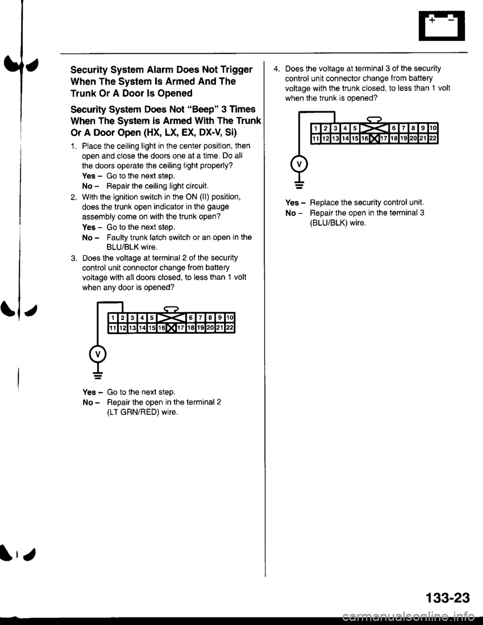
Does the voltage at terminal 2 of the security
control unit connector change trom battery
voltage with all doors closed, to less than I volt
when any door is opened?
Yes - Go to the next step.
No - Repair the open in the terminal 2
(LT GRN/RED) wire.
4. Does the voltage at terminal 3 of the security
control unit connector change from battery
voltage with the trunk closed, to less than 1 volt
when the trunk is opened?
Yes - Replace the security control unit.
No - ReDair the oDen in the terminal 3
(BLU/BLK) wire.
133-23
Page 2108 of 2189
-
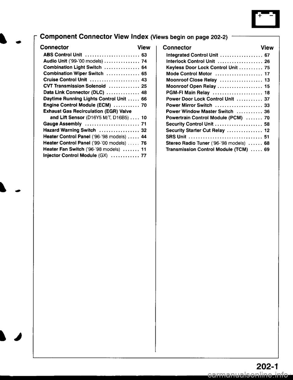
Component Connector View Index (Views begin on page 202-21
Connector View
ABS Control Unit........ ......63
Audio Unit ('99-'00 models) ......74
Combination Light Switch . . . . . . . . . . . . . . . 64
Combination Wiper Switch . . . . . . . . . . . . . . 65
Cruise Control Unit.... .....43
C\TTTransmission Solenoid ............. 25
Data Link Connector (DLC) ..... 48
Daytime Runnlng Lights Control Unit ..... 66
Engine control Module (ECM) ...........70
Exhaust Gas Recirculation (EGR) Valve
and Lift Sensor (D16Y5 Mfl, D1685) . . . . 10
Gauge Assembly .............71
HazardWarnlngSwitch,,. .,,,...,,,,... 32
Heater Control Panel ('96-'98 models) .....44
Heater Control Panel ('99-'00 models) ...., 76
Heater Fan Switch ('96-'98 models) ,,,.... 11
fniector Control Module (GX) ............77
I/
202-1
Connector View
Integrated Control Unit .......,. 67
f nterfock Control Unit .... ...... 26
Keyfess Door Lock Control Unit . . . . , . . . . . 75
Mode Control Motor ... ........'17
Moonroof Close Relay .. .......13
Moonroof Open Relay ... .......15
PGM-FI Main Relay .. .......... 18
Power Door Lock Conlrol Unil ..... ...... 37
Power Mirror Switch .,... ...... 33
Power Window Master Switch .,.........36
Powertrain Control Module (PCM) .......70
Security Control Unit ..., ..,,... 58
Security Starter Cut Belay ... ...,,,....,, 12
SRS Unit ............. 51
Stereo Radio Tuner ('96-'98 models) ...... 68
Transmission Control Module CICM) .....69
Page 2114 of 2189
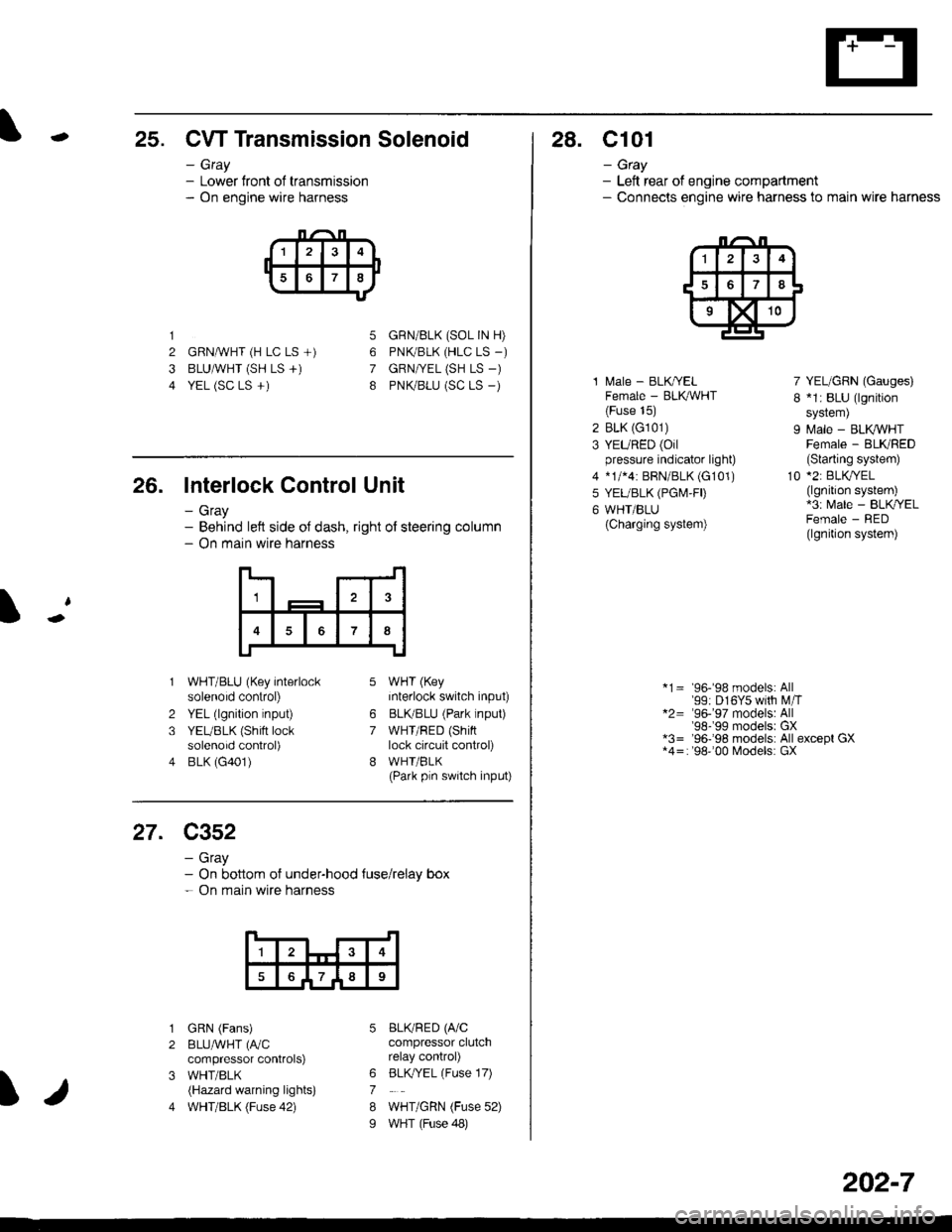
-25. CW Transmission Solenoid
- Gray- Lower front of transmission- On engine wire harness
1
2 GRNAVHT (H LC LS +)
3 BLUAVHT (SH LS +)
4 YEL (SC LS +)
5
6
7
8
GRN/BLK (SOL IN H)
PNK/BLK (HLC LS _)
GRN|VEL (SH LS -)
PNK/BLU (SC LS _)
26. Interlock Control Unit
- Gray- Behind left side oJ dash, right of steering column- On main wire harness
1
7
2
3
4
WHT/BLU (Key interlocksolenoid control)
YEL (lgnition input)
YEUBLK (Shift locksolenoid control)
BLK (G401)
WHT (Key
interlock switch input)
BLKBLU (Park lnput)
WHT/RED (Shinlock circuit control)
WHI/BLK(Park pln switch input)
6
7
27. C352
- Gray- On bottom of under-hood {use/relay box- On main wire harness
1
789
I
1
2
3
4
GRN (Fans)
BLUAVHT (fuC
compressor controlS)
WHT/BLK(Hazard warning lights)
WHT/BLK (Fuse 42)
BLKRED (A/Ccompressor clutchrelay control)
BLK,/YEL (Fuse 17)
WHT/GRN (Fuse 52)
WHT (Fuse 48)
6
7
8
I
28. C101
- Gtay- Left rear of engine compartment- Connecls engine wire harness to main wire harness
1 l\,4ale - BLK/YELFemale - BLK,ryVHT(Fuse 15)
2 BLK (G101)
3 YEURED (Oilpressure indicator light)
4 *1/*4: BRN/BLK (G101)
5 YEUBLK (PGI\4,FD
6 WHT/BLU(Charging system)
7 YEL/GRN (Gauges)
I *1: BLU (lgnition
sYstem)
9 Male - BLK VHTFemale - BLKRED(Slarting system)
10 *2: BLKryEL(lgnition system)*3: Male - BLK/YELFemale - RED(lgnition system)
*1= 96-'98 models: All'99: D16Y5 with M,iT*2= '96-'97 models: All'98-'99 modelsr GX*3= '96-'98 models: All except GX*4=: '98''00 Models: GX
202-7
Page 2137 of 2189
Connector Views (conrd)
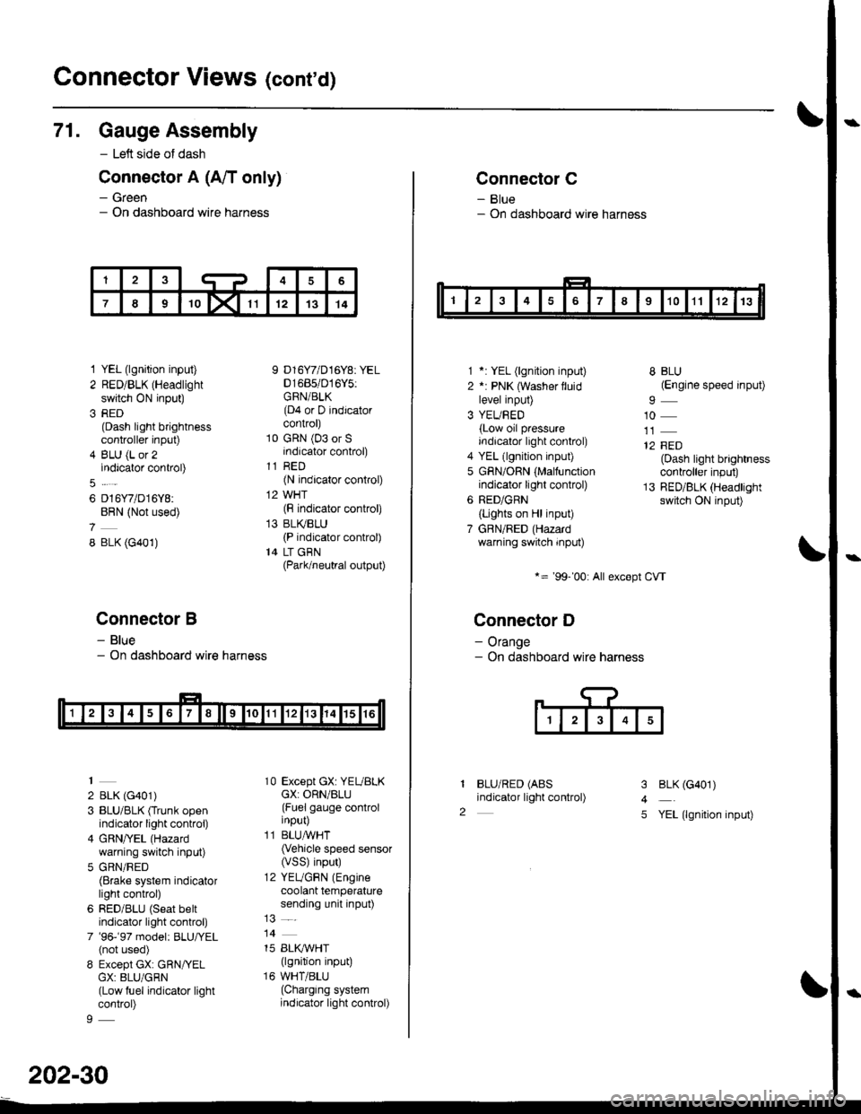
71. Gauge Assembly
- Left side of dash
Connector A (A/T only)
- Green- On dashboard wire harness
1 YEL (lgnition input)
2 RED/BLK (Headlight
switch ON input)
3 RED(Dash light brightnesscontroller input)
4 BLU (L or 2indicator control)
6 D16Y7/D16Y8:BRN (Not used)
8 BLK (G401)
Connector B
- Blue- On dashboard wire harness
2 BLK (G401)
3 BLU/BLK (Trunk openindicator light control)
4 GRN/YEL (Hazard
warning switch input)
5 GRN/RED(Brake system indicatorlight control)
6 RED/BLU (Seat beltindicator light control)
7 '96-'97 model: BLU,ryEL(not used)
8 Except GX: GRN/YELGX: 8LU/GRN(Low fuel indicator lightcontrol)
9 D16Y7/D16Y8: YEL01685/016Y5:GRN/BLK(D4 or D indicatorcontrol)
10 GRN (03 or Sindicator control)
11 RED(N indicator control)
12 WHT(F indicator control)
13 BLI(BLU(P indicator control)
14 LT GBN(Park/neutral output)
10 Except GX: YEUBLKcX: ORN/BLU(Fuel gauge controlinput)
11 BLUAVHT(Vehicle speed sensor(VSS) input)
12 YEUGRN (Engine
coolant temperaturesending unit input)
14
15 BLI(IVHT(lgnition input)
16 WHT/BLU(Charging systemindicator light control)
202-30
Connector C
- Blue- On dashboard wire harness
1 *: YEL (lgnition input)
2 *: PNK (Washer lluidlevel input)
3 YEUBED(Low oil pressureindicator light control)
4 YEL (lgnition input)
5 GRN/ORN (Malfunctionindicator light control)
6 RED/GRN
{Lights on Hl input)
7 GBN/RED (Hazardwarning switch input)
*= '99-'00: All except CVT
Connector D
- Orange- On dashboard wire harness
BLU/RED (ABS
indicator light control)
8 BLU(Engine speed input)
10
12 FED(Dash light brightnesscontroller input)
13 RED/BLK (Headlightswitch ON input)
I
2
3
4
5
BLK (G401)
YEL (lgnition input)
Page 2168 of 2189
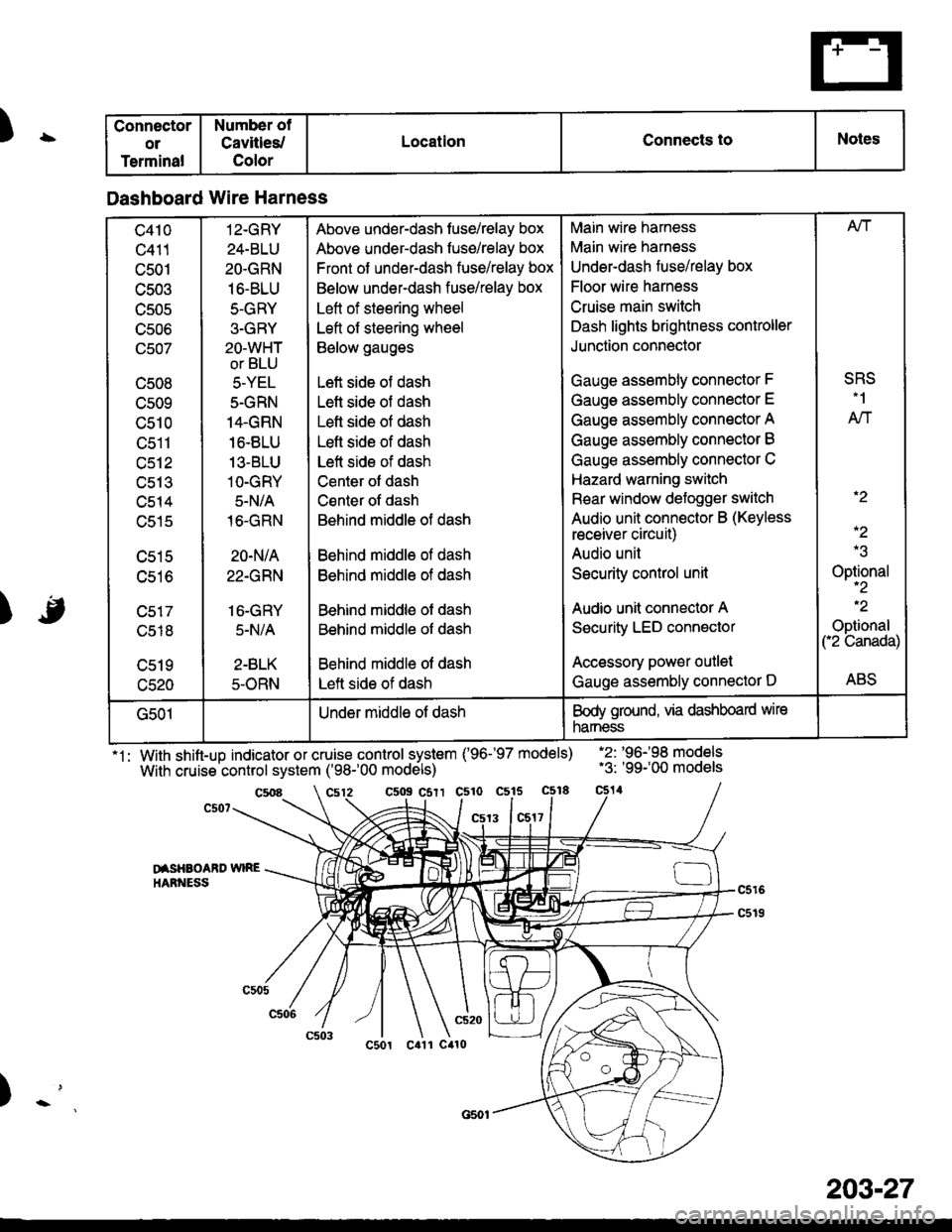
)\
) -,
.'
'1: With shift-up indicator or cruise control system ('96-'97 models)
With cruise control system ('98-'00 models)
.2: '96198 models.3: '99-'00 models
c5o9 csrr c510 c515
13 1c517
DISHAOABD w|REIIARNESS
Connector
or
Terminal
Number of
Cavities/
Color
LocationConnects toNotes
Dashboard Wire Harness
c410
c411
c501
c503
TJJUC
UCUO
(Jcu/
c508
cs09
c510
tJctl
c512
uc t.t
c514
c515
c516
c518
c520
12-GRY
24-BLU
2O.GRN
16-BLU
5-GRY
3-GRY
2O-WHT
or BLU
5-YEL
5-GRN
14.GRN
16.8LU
13-BLU
1O-GRY
5-N/A
16-GRN
20-N/A
22.GRN
16-GRY
5.N/A
2-BLK
5-ORN
Above under-dash fuse/relay box
Above under-dash fuse/relay box
Front of under-dash fuse/relay box
Below under-dash fuse/relay box
Left of steering wheel
Left of steering wheel
Below gauges
Left side of dash
Lett side of dash
Left side of dash
Lefl side of dash
Left side of dash
Center ot dash
Csnter of dash
Behind middle of dash
Behind middle ol dash
Behind middle of dash
Behind middle of dash
Behind middle of dash
Behind middle of dash
Left side of dash
Main wire harness
Main wire harness
Underdash fuse/relay box
Floor wire harness
Cruise main switch
Dash lights brightness controller
Junction connector
Gauge assembly connector F
Gauge assembly connector E
Gauge assembly connector A
Gauge assembly connector B
Gauge assembly connector C
Hazard warning switch
Rear window defogger switch
Audio unit connector B (Keyless
receiver circuit)
Audio unil
Security control unit
Audio unit connector A
Security LED connector
Accessory power outlet
Gauge assembly connector D
Afi
SRS.1
AN
.2
-2
Optional-2
.2
Optional("2 Canada)
ABS
G501Under middle of dashBody ground, via dashboard wire
narness
203-27