1996 HONDA CIVIC Gauge control unit
[x] Cancel search: Gauge control unitPage 140 of 2189

13. Remove the upper radiator hose' heater hose and
water bYPass hose
WATEREYPASSHOSEUPPERRADIATORHOSE
14.
HEATERHOSE
Remove the engine wire harness connectors and
wire harness clamps from the cylinder head and the
intake manifold.
o Four fuel injector connectors
. Engine coolant temperature (ECT) sensor con-
nector
a
a
a
ECT switch connector
ECT gauge sending unit connector
Throttle position sensor connector
Manitold absolute pressure (MAP) sensor con-
nector
Primary heated oxygen sensor (primary HO2S)
connector
Secondary heated oxygen sensor (secondary
HO2S) connector (D16Y7 engine)
Exhaust gas recirculation (EGR) valve lift sensor
connector (D16Y5 engine)
. VTEC solenoid valve connector (Dl6Y5, D16Y8
engrnes)
. VTEC pressure switch connector (D16Y5. D16Y8
engrnes,
. ldle air control (lAC) valve connector
15.Remove the spark plug caps and distributor from
the cylinder head.
Remove the uPPer bracket.
NOTE:
. Use a jack to support the engine before the
upper bracket is removed.
. Make sure to place a cushion between the oil
pan and the jack.
12 x 1.25 mm
74 N.m {7.5 kgf m.
sil lbl.ftl
UPPERBRACKET
'17. Remove the cylinder head cover'
CYLINDERHEAD COVER
(cont'd)
6-29
Page 179 of 2189
WATER BYPASS
HOSE
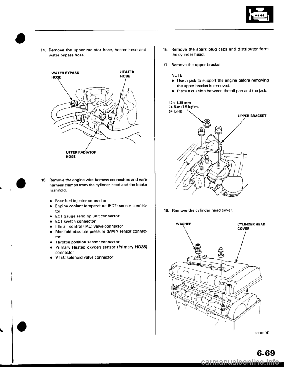
14. Remove the upper radiator hose, heater hose and
water bvpass hose.
HEATER
Remove the engine wire harness connectors and wlre
harness clamps from the cylinder head and the intake
manifold.
Four fuel injector connector
Engine coolant temperature (ECT) sensor connec-
tor
ECT gauge sending unit connector
ECT switch connector
ldle air control (lAC) valve connector
Manifold absolute pressure (MAP) sensor connec-
tor
Throttle position sensor connector
Primary Heated oxygen sensor (Primary HO2S)
connecror
VTEC solenoid valve connector
15.
a
a
a
a
a
\
16.
17.
Remove the spark plug caps and distributor form
the cylinder head.
Remove the upper bracket.
NOTE:
. Use a jack to support the engine before removing
the upp€r bracket is removed.
. Place a cushion between the oil panandthejack.
12 x 1.25 fin74 N.m 17.5 kgtm,
UPPER BRACKET
18. Remove the cylinder head cover.
{cont'd)
6-69
Page 277 of 2189
Component Locations
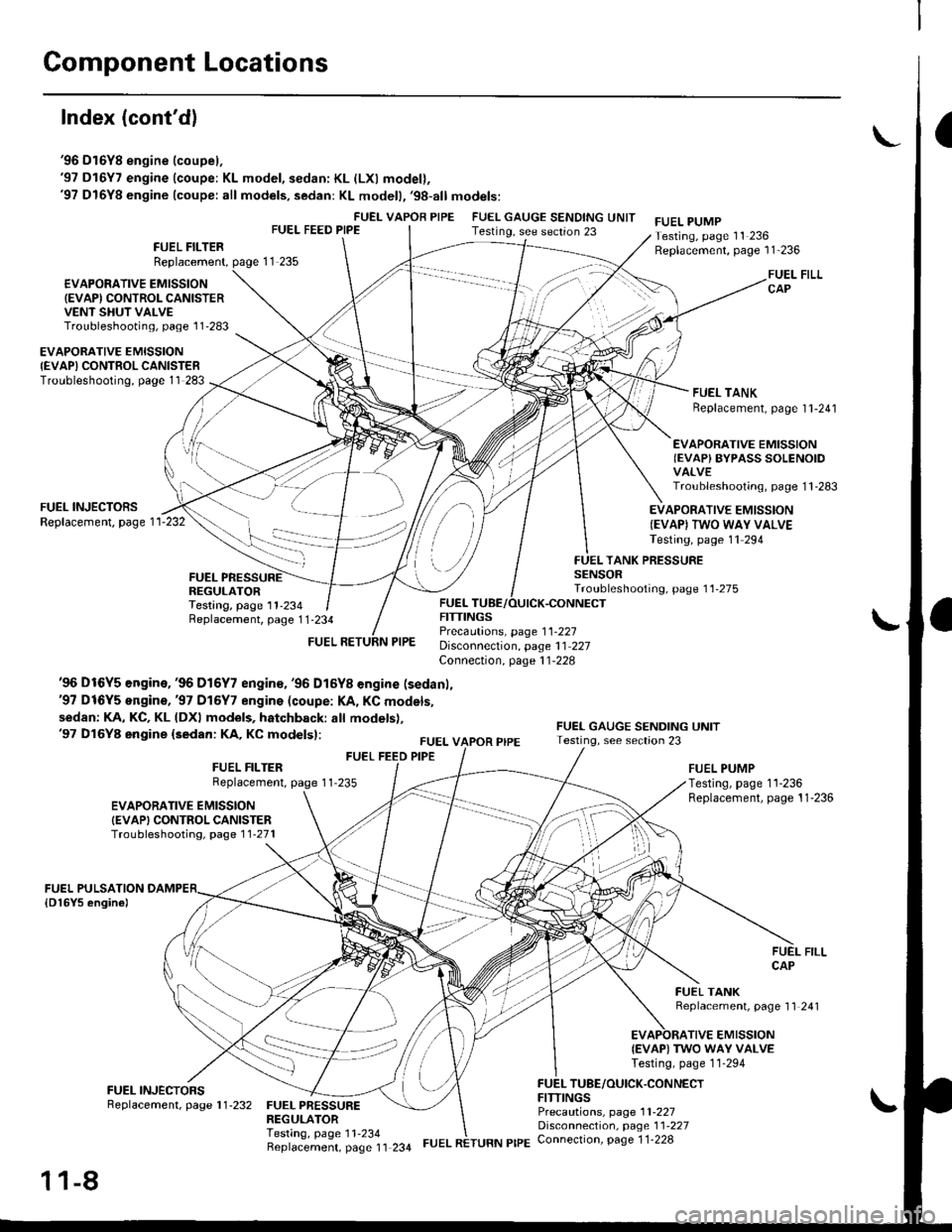
Index (cont'dl
'96 D16Y8 engine (coupel,'97 D16Y7 engine (coupe: KL model, sedan: KL (LXl model),'97 D16Y8 engine (coupe: all models, sedan: KL modell,'98-all models:
FUEI- VAPOR PIPEFUEL FEED PIPEFUEL GAUGE SENDING UNITTesting, see section 23FUEL PUMPTesting, page 11 236Replacement, page 11 236FUEL FILTERReplacement,
€VAPOFATIVE EMISSION(EVAPI CONTROL CANISTERVENT SHUT VALVETroubleshooting, page l1'283
FUEL FILLCAP
FUEL TANKReplacement, page I l-241
EVAPORATIVE EMISSIONIEVAPI CONTROLCANISTERTroubleshooting, page 11 283
EVAPORATIVE EMISSIONIEVAP) BYPASS SOLENOIDVALVETroubleshooting, page 1 1 -283
FUEL INJECTORSReplacement, page 1 1-232EVAPORATIVE EMISSION(EVAPI TWO WAY VALVETesting, page 11 294
FUELREGULATORTesting, page 11-234
TANK PRESSURESENSORTroubleshooting, page 11-275
Replacement, page 1 1-234
'96 Dt6Y5 engine,'96 D16Y7 engin€, '96 D16Y8 engine (sedanl,'97 D16Y5 engine,'97 Dl6Y7 engins (coupe: l(A, KC models,
sedan: KA, KC, KL (DXl models, hatchback: all models),'97 Dl6Y8 engine (sedan: KA, KC modelsl:
FUEL FEED PIPE
FUELFITTINGSPrecautions, page 1 1-227Disconnection, page 11 227Connection, page 11-228
FUEL VAPOR PIPE
FITTINGS
EVAPORATIVE EMISSIONIEVAPI CONTROL CANISTERTroubleshootiog, page 1 1-271
FUEL FILTERReplacement, page 1 1-235FUEL PUMPTesting, page 11-236Replacement, page 11-236
FUEL TANKBeplacement, page 11 241
TIVE EMISSION{EVAP) TWO WAY VALVETesting, page 11-294
TUBE/OUICK.CONNECT
FUEL PRESSUREREGULATORTesting, page 11'234Beplacement, page 11 234
Precautions, page 1 1-227Disconnection, page 11'227Connection, page 1 1-228
11-8
FUEL RETURN PIPE
Page 278 of 2189

'99 - 00 models:
EVAPORATIVE EMISSIONIEVAP} PURGE CONTROLSOLENOID VALVETroubleshooting, page 1 1'288FUEL GAUGE SENDING UNITTesting, see section 23
FUEL VAPOR PIPE
ONBOARD REFUELING VAPORR€COVERY IORVRIVENT SHUT VALVETest, page 11 296
EVAPORATIVE EMISSION
{EVAP) CONTROL CANISTERVENT SHUT VALVETroubleshooting, Page 1 1_288
EVAPORATIVE EMISSION
FUEL FILTERBeplacement, page 11-235
FUEL FEED PIPE
FUEL RETURN PIPE
FUEI- PUMPTesting, page 11 236Replacement, page 11-236
FUEL FILLCAP
{EVAPI CONTROLTroubleshooting, page 1 1_288
FUELPULSATION DAMPEB
FUEL INJECTORSReplacement, page 1 1'232
FUEL PRESSUREREGULATOR
EVAPORATIVE EMISSION
{EVAP) BYPASS SOLENOIDVALVETroubleshooting, page 1 1-288
FUELRAIL
FUEL TANK PRESSURESENSOBTroubleshooting, Page 1 1'274
EVAPORATIVE EMISSIONIEVAPI TWO WAY VALVETesting, page 11 295
Testing, page 11-234Replacement, page 11 234FUEL TUBE/OUICK.CONNECTFITTINGSPrecautions, page 1 l-227Disconnection, page 11 227Connection, page 1 1-228
Replacement, page 1 1-241
I(cont'd)
1 1-9
Page 309 of 2189
System Description
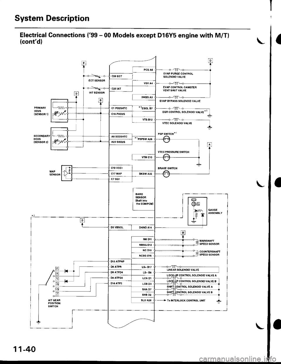
Electrical Connections ('99 - 00 Models except Dl6Y5 engine with M/Tl
(cont'd)
T:I
1
0
EVAP PURGE CONTROLSoLENOtOVAIVEc26 ECTECTSENSOR
D
EVAP COI{TROL CANISIE R
IATSENSOR
ta-t
c25 tAT
HO2S(sENSoFt
EVAP BYPASS SOI.ENOID VALVE
cl Po2s{tc"Eso! 87
)wEGF coNTRoL solENoro vaLvE'"c16PHO2S
vlsBr2VTEC SOLEr{O|D VATVE
H02SiSENSOR 2),wA23 SHO2S
VTECPFESSUFESWITCH
sEt{soR
-t,.1 f
I
BRAKE SWITCH
c7 sG1
SENSOB(Buln l oF
@E
lfil
*_r
/V | GAUGE
* lassEMBLIIl-
SPEEOSENSOR
tr
D5VBSOLo4tND A14
N DTI
NC DTOSPEEDSENSOR
LS+ Bl7UNEAR SOLENOID VALVET'I AT?04LS- a3
LOCIPr. l03alP03LCA 01P CONTBOISOIENOiDVALVE BLCB 03IOI{IROL SOLENOID VAIV€ A
SHIFI COTITROL SOLENOID VALVE BSHE D2
POStTtON
t----
I
To IIIT!FLOCK CONTROL UNIT
--t
L
l-
I
I
11-40
-.._.._.._.._l
,'-J
Page 1090 of 2189
lnspection and Adjustment
Pump Pressure Check
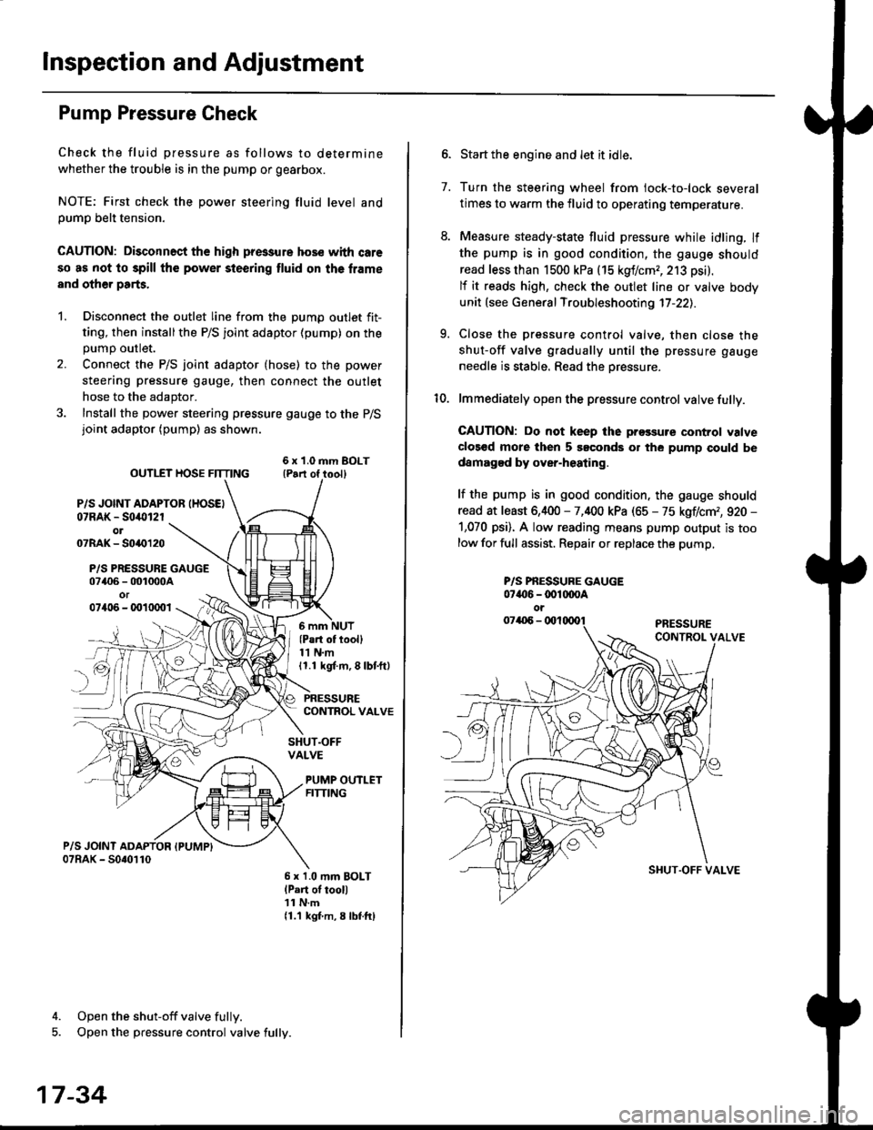
Check the fluid pressure as follows to determine
whether the trouble is in the pump or gearbox.
NOTE: First check the power steering fluid level andpump belt tension.
CAUTION: Disconnect the high pr$sure hos€ with care
so as not lo spill the power sieering tluid on tha frame
and other parts.
1. Disconnect the outlet line from the Dumo outlet fit-
ting, then installthe P/S joint adaptor (pump) on the
Dumo outlet.
2. Connect the P/S joint adaptor (hose) to the power
steering pressure gauge, then connect the outlet
hose to the adaptor.
3. Install the power steering pressure gauge to the P/Sjoint adaptor (pump) as shown.
ourlEr HosE FnrNo ,t"ll lrilu"ott
P/S JOINT ADAPTOB IHOSEI07RAK - S0i10l2rol07RAK- 50{{)120
P/S PRESSURE GAUGE07406 - 001000Aor07406 - 0010001
4. Open the shut-off valve fully.
5. Open the pressure control valve fully.
17-34
(Pa.t of tooll11 N.m11.1 kgt m, 8 lbf.ftl
PRESSURECONTROL VALVE
SHUT.OFFVALVE
PUMP OUTLETFITTING
6 x 1.0 mm BOLTlPart of tool)11 N.m11.1 kgf m, 8 lbtftl
7.
Start the engine and let it idle.
Turn the steering wheel from lock-to-lock several
times to warm the fluid to operating temperature.
Measure steady-state fluid pressure while idling. If
the pump is in good condition, the gauge should
read less than 1500 kPa (15 kgf/cmr, 213 psi).
lf it reads high, check the outlet line or valve body
unit (see General Troubleshooting 17-22).
Close the pressure control valve, then close the
shut-off valve gradually until the pressure gauge
needle is stable. Read the oressure.
lmmediately open the pressure control valve fully.
GAUTION: Do not keep lhe prossure control valve
clos€d more then 5 soconds or the pump could be
damagod by over-heating.
lf the pump is in good condition, the gauge should
read at least 6,400 - 7,400 kPa (65 - 75 kgflcm,, 920 -
1,070 psi). A low reading means pump output is too
low for full assist. Repair or replace the pump,
9.
P/S PBESSURE GAUGE07{16 -@1@OA
oi
SI{UT.OFF VALVE
Page 1207 of 2189
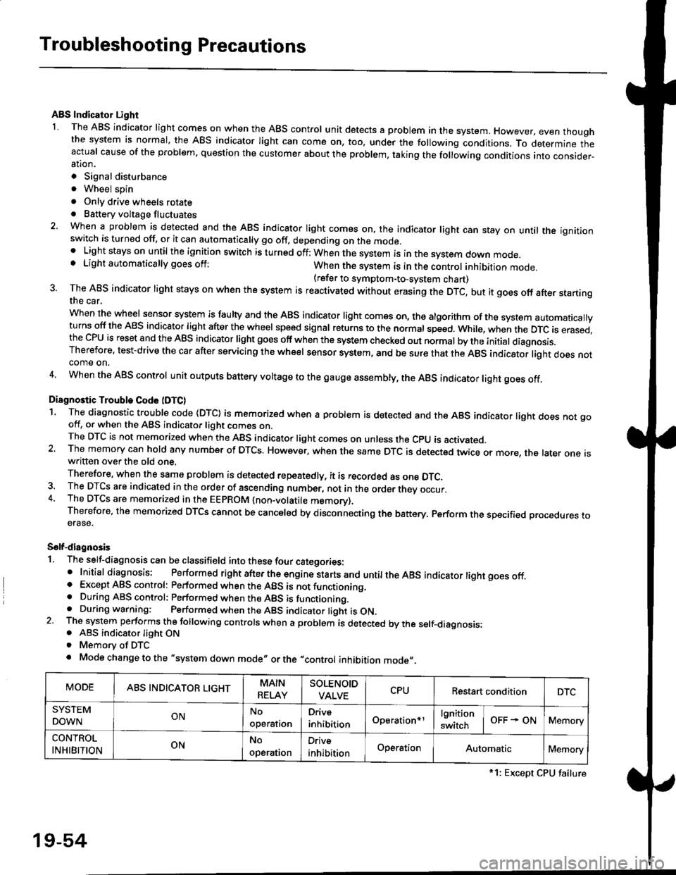
Troubleshooting Precautions
ABS Indicator Light
I The ABS indicator light comes on when the ABS control unit detects a problem in the system. However, even thoughthe system is normal, the ABs indicator light can come on, too, under the following conditions. To determine theactual cause of the problem, question the customer about the problem, taking the following conditions into consider-ation.
. Signal disturbance
. Wheel soin
. Only drive wheels rotate. Battery voltage fluctuates
2. When a problem is detected and the ABS indicator light comes on, the indicator light can stay on untat the ignitionswitch is turned off, or it can automatically go off, depending on the mode.. Lightstayson until the ignition switch isturned off;When the system is inthesvstem down mode.o Light automatically goes off:When the system is in the control inhibition mode.(refer to symptom-to-system chart)3 The ABS indicator light stays on when the system is reactivated without erasing the DTC, but it goes off after startingthe car.
when the wheel sensor system is faulty and the ABS indicator light comes on, the algorithm of the system automaticallyturns off the ABS indicator light after the wheel speed signal returns to the normal speed. while, when the DTC is erased,the CPU is reset and the ABS indicator light goes off when the system check€d out normal by the initial diagnosis.Therefore, test-drive the car after servicing the wheel sensor system, and be sure that the ABS indicator light does notcome on.
4. When the ABS control unit outputs battery voltage to the gauge assembty, the ABS indicator light goes off.
Diagnostic Trouble Code (DTC)
1. The diagnostic trouble code (DTC) is memorized when a problem is detected and the ABS indicator light does not gooff, or when the ABS indicator light comes on.The DTC is not memorized when the ABs indicator right comes on unress the cpU is activated.2. The memory can hold any number of DTCs. However, when the same DTc is detected twice or more, the later one iswritten over the old one.
Therefore. when the same problem is detected repeatedly, it is recorded as one DTC.3. The DTCS are indicated in the order of ascending number, not in the order thev occur.4. The DTCS are memorized in the EEpROM {non-volatile memorv}.Therefore, the memorized DTCS cannot be canceled by disconnecting the battery. perform the specified orocedures toerase.
Solf-diagnosis
1. The self-diagnosis can be classifield into these four categories:' Initial diagnosis; Performed right after the engine sta rts and untiltheABs indicator light goes off.o Except ABS control: Performed when the ABS is not functioning,. During ABS control: Performed when the ABS is functioning.. During warning: Performed when the ABS indicator light is ON.2 The system performs the following controls when a problem is detected by the self-diagnosis:. ABS indicator light ON. Memory of DTC
. Mode change to the "system down mode,, or the "control inhibition mode,,.
MODEABS INDICATOR LIGHTMAIN
RELAY
SOLENOID
VALVECPURestart conditionDTC
SYSTEM
DOWNONNo
operal|on
Drive
inhibitionOperation+rlgnition
switchOFF - ONMemory
CONTROL
INHIBITIONONNo
operat|on
Orive
inhibitionOperationAutomaticMemory
*1: Except CPU failure
19-54
Page 1216 of 2189
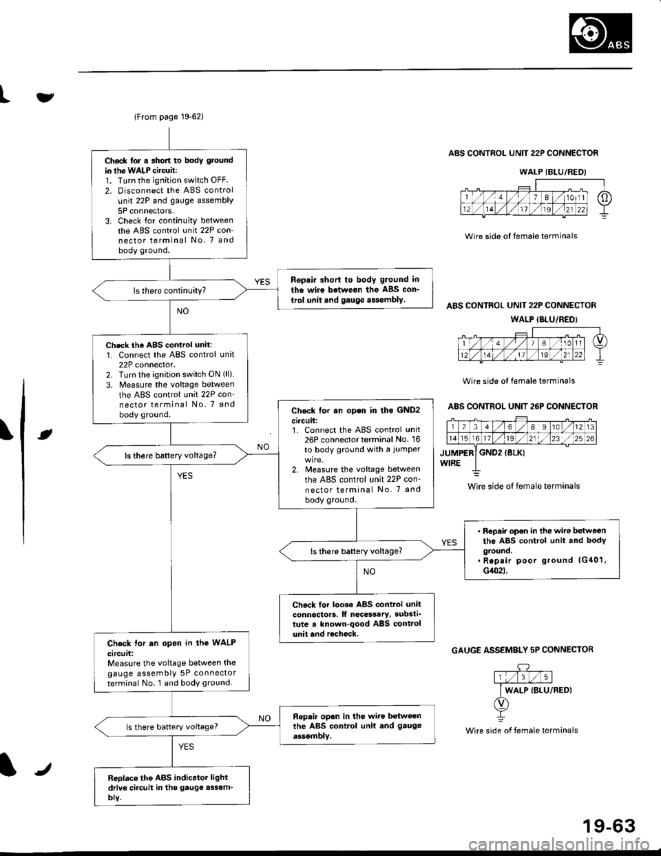
lFrom page 19-621
Ch6ck lor . short to body ground
in ihe WALP Gircuit:1. Turn the ignition switch OFF.
2. Disconnect the ABS control
unit 22P and gauge assembly
5P connectors.3. Check for continuity betweenthe ABS control unit 22P con-nector terminal No. 7 andbody ground.
Ropair short to body g.ound in
tho wire betweon the ABS con_
trol unit and gauge aasembly.
Check the AgS cortrol unit:1. Connect the ABS control unit22P connector.2. Turn lhe ignition switch ON (ll).
3. Measure the voltage between
the ABS control unit 22P con'nector terminal No, 7 and
body ground.Check tor rn open in lho GND2
circuit:1. Connect the ABS control unit26P connector terminal No. 16
to body ground with a iumper
2. Measure the voltage between
the ABS control unit 22P con-
nector terminal No. 7 and
body ground.
ls there baftery voltage?
' Repair op€n in the wit€ betweenthe ABS control unit and bodyground.. Rep.ir poor ground lG40'1,G1(}2t.
ls there battery voltage?
Check tor loo3€ ABS control unitconnector!. lf necesaary, substi_tute a known-qood ABS controlunit and r€check,Check lor an open in the WALP
circuit:Measure the voltage between thegauge assembly 5P connectorterminal No. 1 and body ground.
Ropai. opon in the wiro botweenthe ABS control unit end gauge
assemblv.ls there battery voltage?
Replace the ABS indicrtor lightdriv6 ci.cuit in the gtuge assem-bly.
tv
Wire side ol female terminals
ABS CONTROL UNIT 22P CONNECTOR
ABS CONTROL UNIT 22P CONNECTOR
WALP {BLU/REDI
Wire side ol female terminals
ABS CONTROL UNIT 26P CONNECTOR
rt
GAUGE ASSEMBLY 5P CONNECTOR
.DY
Wire side of female terminals
WALP {BLU/REDI
wire side ol female terminals
J
19-63