Page 1068 of 2189
Steering Gearbox
Reassembly (cont'd)
21.
'19.
20.
Install the boot band so that the locking tabs of the
band (stake points) are in the range shown below.
{Tabs should face up and slightly forwaro.,
Bend both sets of locking tabs.
Lightly tap on the doubled-over portions to reduce
their height.
CAUTION: Stake the band locking tabs firmly.
22. Slide the rack right and left to be certain that the
boots are not detormed or twisted.
Stake points
+ Fronr
Lett Boot Band(Viewed from the left side)Right Boot Bend(Viewed from the right side)
17-12
Page 1069 of 2189

)
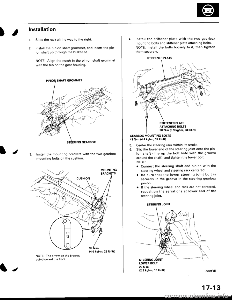
lnstallation
Slide the rack all the way to the righl
Install the pinion shaft grommet, and insert the pin
ion shaft up through the bulkhead.
NOTE| Align the notch in the pinion shaft grommet
with the tab on the gear housing.
1.
2.
J3. Install the mounting brackets with the two gearbox
mounting bolts on the cushion.
NOTE: The arrow on the bracketpoint toward the front.
STEEBING GEARBOX
{4.0 kgt.m,29 lbf.ftl
J
4. Install the stiffener plate with the two gearbox
mounting bolts and stiffener plate attaching bolts.
NOTEr Install the bolts loosely first. then tighten
them securely.
GEARBOX MOUNTING EOLTS43 N.m {4.4 kgf.m, 32 lbf'ftl
5. Center the steering rack within its stroke
6. Slip the lower end ot the steering joint onto the pin
ion shaft (line up the bolt hole with the groove
around the shaft), and tighten the lower bolt.
NOTE:
. Connect the steering shaft and pinion with the
steering wheel and steering rack centered
Be sure that the lower steering joint bolt is
securely in the groove in the steering gearbox
pin ion.
lf the steering wheel and rack are not centered,
reposition the serrations at lower end of the
steering ioint.
STEERING JOINT
STEERING JOINTLOWER BOLT22 N.m{2.2 kgf.m, 16lbf'ft}(cont'd)
I t- t5
STIFFENER PLATE
ATTACHING BOLTS38 N.m (3.9 kgf.m.28lbf.ftl
Page 1071 of 2189

Component Locations
I
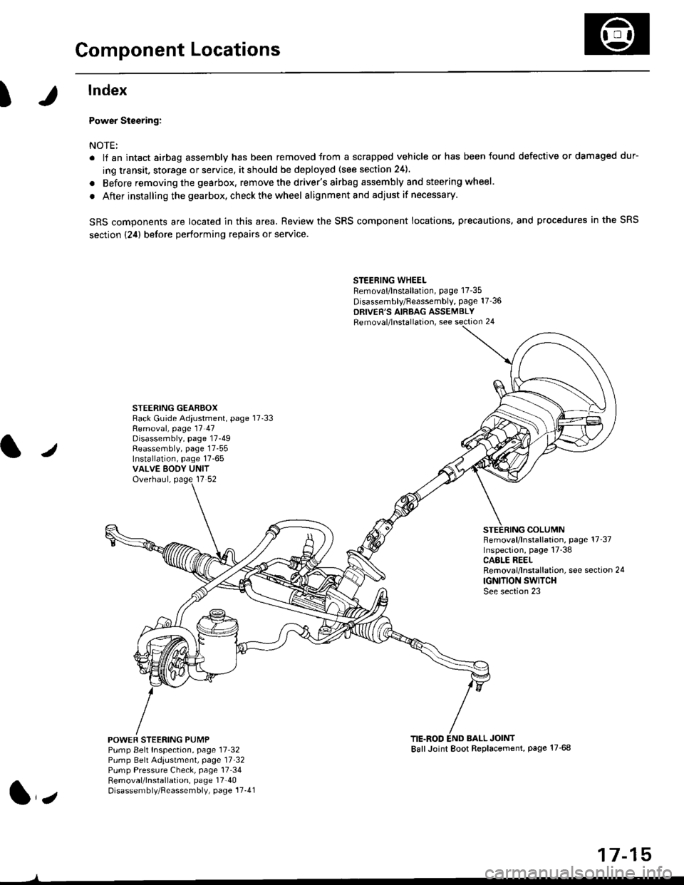
lndex
Power Steering:
NOTE:
. li an intact airbag assembly has been removed trom a scrapped vehicle or has been found defective or damaged dur-
ing transit. storage or service, it should be deployed (see section 24).
. Before removing the gearbox, remove the driver's airbag assembly and steering wheel.
. After installing the gearbox, checkthewheel alignmentand adjust if necessary.
SRS components are located in this area. Review the SRS component locations. precautions, and procedures in the SRS
section {24} before performing repairs or service.
STEERING WHEELRemoval/lnstallation, page 17-35
Disassembly/Feassembly, page 17-36
DRIVER'S AIRBAG ASSEMBLYRemoval/lnstallation, see section 24
STEERING GEAREOXRack Guide Adiustment, page 17'33
/
Removal, page 17 47Disassembly, page 17-49Reassembly, page 17-55Installation, page 17-65VALVE EODY UNITOverhaul, page 17 52
COLUMNFemoval/lnstallation, page 17-37Inspection, page 17-38CASLE REELRemoval/lnstallation, see section 24
IGNITION SWITCHSee section 23
POWEF STEERING PUMPPump Belt Inspection, page 11-32Pump Belt Adiustmenl, page 11'32Pump Pressure Check, page 17 34Removal/lnstallation, page 17'40Disassembly/Reassembly, page 17-41
TIE.ROD END BALL JOINTBallJoint Boot Replacement, page 17-68
1,,
17-15
Page 1072 of 2189
System Description
Fluid Flow Diagram
The system is a compact rotary-valve-type power steering, connected to the steering gearbox. The fluid pressure is pro-
vided by a vane-type pump which is driven by the engine crank pulley. The amount of fluid and pressure is regulated by
the flow control valve built into the pump. The fluid pressure from the pump is delivered to the valve body unit around the
pinion of the steering gearbox. The valve inside the valve body unit controls the hydraulic pressure and changes the direc-
tion of the flow. The fluid then flows to the power cylinder. where rack thrust is generated. Fluid returning from the power
cylinder flows back to the reservoir, where the fluid is "filtered" and supplied to the pump again.
RESERVOIR
VALVE BOOY UNIT
SUB.VALVE
FLOW CONTROL VALVESTEERING GEARBOX
17-16
Page 1076 of 2189

System Description
Steering Gearbox
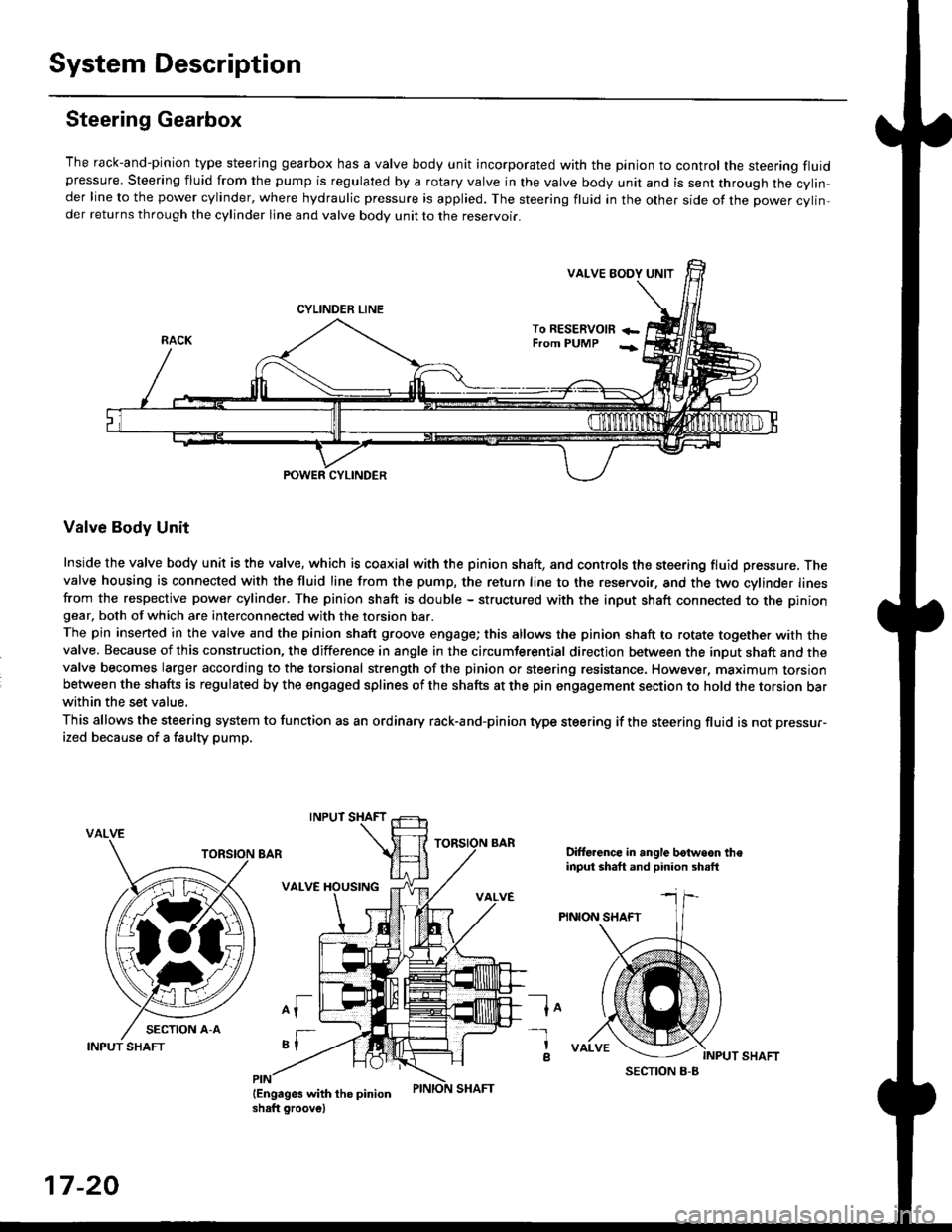
The rack-and-pinion type steering gearbox has a valve body unit incorporated with the pinion to control the steering fluidpressure. Steering fluid from the pump is regulated by a rotary valve in the valve body unit and is sent through the cylin,der line to the power cylinder, where hydraulic pressure is applied. The steering fluid in the other side of the power cylin,der returns through the cylinder line and valve body unit to the reservoii.
VALVE EODY UNIT
CYLINDER LINE
To RESERVOm +-From PUMP -;
POWER CYLINDER
Valve Body Unit
Inside the valve body unit is the valve, which is coaxial with the pinion shaft, and controls the steering fluid pressure. Thevalve housing is connected with the fluid line from the pump, the return line to the reservoir, and the two cylinder linesfrom the respective power cylinder. The pinion shaft is double - structured with the input shaft connected to the piniongear, both of which are interconnected with the torsion bar.
The pin inserted in the valve and the pinion shaft groove engage; this allows the pinion shaft to rotate together with thevalve. Because of this construction, the difference in angle in the circumferential direction between the input shaft and thevalve becomes larger according to the torsional strength of the pinion or steering resistance. However, maximum torsionbetween the shafts is regulated by the engaged splines of the shafts at the pin engagement section to hold the torsion barwithin the set value,
This allows the steering system to function as an ordinary rack-and-pinion type steering if the steering fluid is not pressur-
ized because of a faulty pump,
VALVE
Difforence in angle botwoon theinput shaft and pinion shsft
PINION SHAFT
lo
INPUT SHAFT
-l
a
17-20
INPUT SHAFT
Page 1077 of 2189

Pressure Control
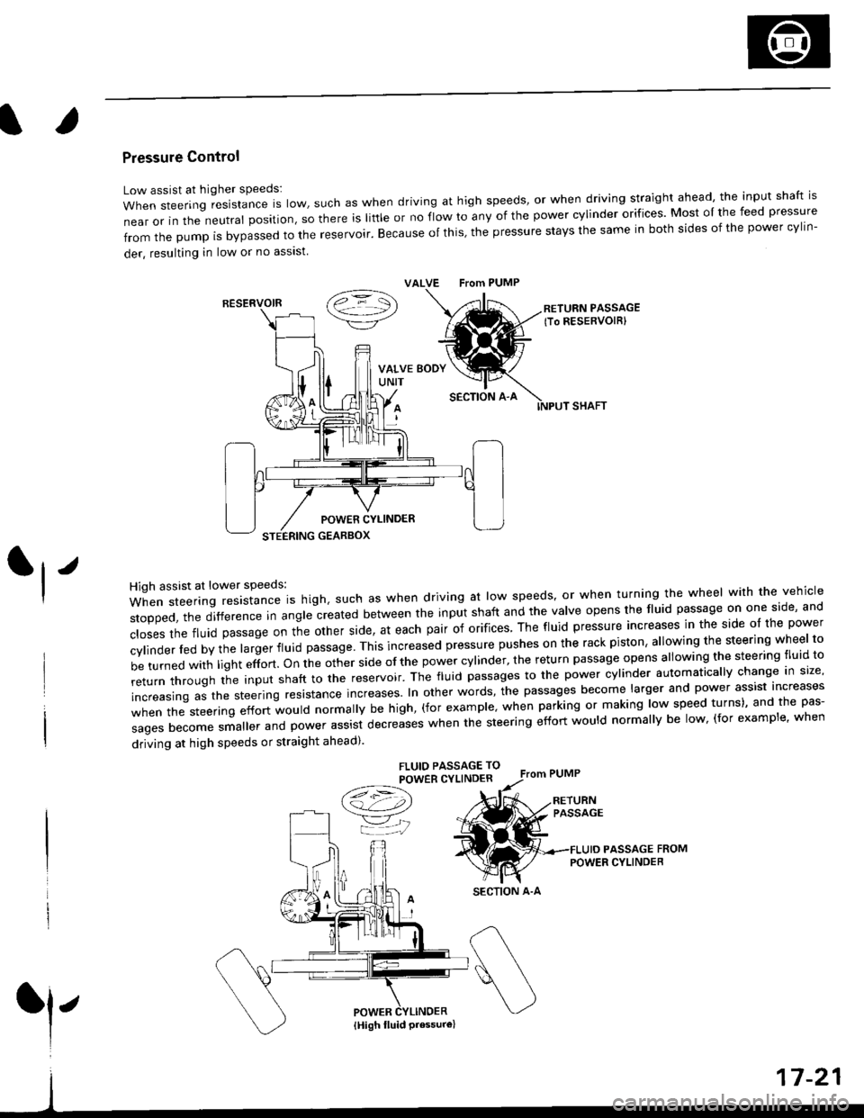
Low assist at higher speeds:
WhensteeringresistanceIsIow,suchaswhendrivingathighspeeds,orwhendrivingstraightahead,theinputshaftis
near or in the neutral position, so there is little or no fiow ro any of the power cylinder orifices. Most oI the feed pressure
fromthepumpisbypassedtothereservoir.Becauseofthis,thepressurestaysthesameinbothsidesofthepowercy||n-
der, resulting in low or no asslst
VALVE From PUMP
SECTION A-A
RETURN PASSAGElTo RESERVOIRI
POWER CYLINDER
STEERING GEARBOX
High assist at lower speeds:
When steering resistance is high. such as when driving at low speeds' or when turning the wheel wirh the vehicle
stopped,thedifference|nang|ecreatedbetweentheinputshaftandtheVa|veopensthef|uidpassageononeside,and
c|osesthefluidpassageontheotherside,ateachpairoforifices'Thef|uidpressureincreasesinthesideo|thepower
cy|inder|edbythe|argerf|uidpassage'Thisincreasedpressurepushesontherackpiston,a|lowingthesteeringwhee|to
be turned with light effort. on the other side of the power cylinder, the return passage opens allowing the steering tluid to
returnthroUghtheinputshafttothereservoir'Thef|uidpassagestothepowercy|inderautomatica||ychangeins|ze,
increasing as the steering resrstance increases. In other words, the passages become larger and power assist increases
when the steering effort would normally be high, (for example' when parking or making low speed turns)' and the pas-
sagesbecomesma||erandpowerassistdecreaseswhenthesteeringeffortwou|dnorma||ybe|ow,(forexamp|e,when
driving at high speeds or straight ahead).
FLUIO PASSAGE TO
POWER CYLINDER
/t=\\a!-4,))
=YjJ
RESERVOIR
SECTION A-A
l'
{High fluid Pressure}
Page 1079 of 2189
I
AbnormalDeformed
Faulty cylinder lines
Adiustment OK
Faulty valve body unit
Normal
IICompair the steering to another alike
vehicle.
/
Check the force required to turn
the wheel (see Page 17 30i
Start the engine and measure the
force required to turn the wheel
to the right and left. Difference of
the lorce required to turn the
wheel to the right and to the Ieft
should be 2.9 N 10 3 kgf, 0.7 lbf)
or below.
Check for bent rack shaft
Check rack guide adiustment (see
page 17-33).
(cont'd)
17 -23
1,,
Page 1080 of 2189
Troubleshooting
General Troubleshooting (cont'd)
Assist (excessively light steering) athigh speed.
Shock or vibration when wheel isturned to {ull lock.
Steering wheelwill not returnsmoothly.
lf the problem is not corrected byadiusting the rack guide, adjustthe front wheel alignment lseesection 181.
Check the rack guide for properadiustment (see page 17 33).
Check the rack guide for properadjustment (see page 17-33).
Rack guide is adjusted properly.
lfthe problem is not corrected byadjusting the rack guide, replacethe gearbox.Check the belt for slippage andaolust as necessary {see page11 32).
A and B cylinder lines are nor-mal, check wheel alignment (seesection 18).
Wheel alignment is abnormal,adjust as needed.
Wheel alignment is normal.Check the steering wheel opera-tion and power assist check {seepage lT-30).
It the measurements are out ofspecifications, adjust the ra ckguide.
lf the problem is not corrected byadjusting the rack guide, replacethe gearbox.
17-24