Page 129 of 2189

Timing Belt
Inspection
1.
2.
3.
Remove the cylinder head cover.
. Refer to page 6 46 when installing.
Remove the upper cover (see page 6 19).
Inspect the timing belt for cracks and oil or coolantsoakrng.
NOTE:
. Replace the belt if oil or coolant soaKeo.. Remove any oil or solvent that gets on the belt.
Rotate pulleyand inspect belt.
After inspecting, retorque the crankshaft pullev bolt{see page 6- 16).
o- I6
Tension Adjustment
CAUTION: lt*ays aa;j"t the timing bett rension withthe engine cold.
NOTE:
. The tensioner is spring loaded to apply tension to thebelt automatically after making the following adjustment.
. Always rotate the crankshaft counterclockwise whenviewed from the pulley side. Rotating it clockwisemay result in improper adjustment of the belt ten-sion.
. lnspect the timing belt before adjusting the belt ten-ston.
1.Remove the cylinder head cover.
. Refer to page 6,46 when installing.
Remove the upper cover (see page 6,'19).
Rotate the crankshaft five or six revolutions to setthe belt.
Set the No. 'l piston at TDC (see page 6-21).
Loosen the adjusting bolt 180'.
2.
3.
4.
5.
\I
ADJUSTING BOLT44 N.m {4.5 kgt m,33 rbf.ft)
7.
8.
Rotate the crankshaft counterclockwise three teethon the camshaft pulley.
Tighten the adjusting bolt.
After inspecting, retorque the crankshaft pulley bolt(see page 6-16).
Page 130 of 2189

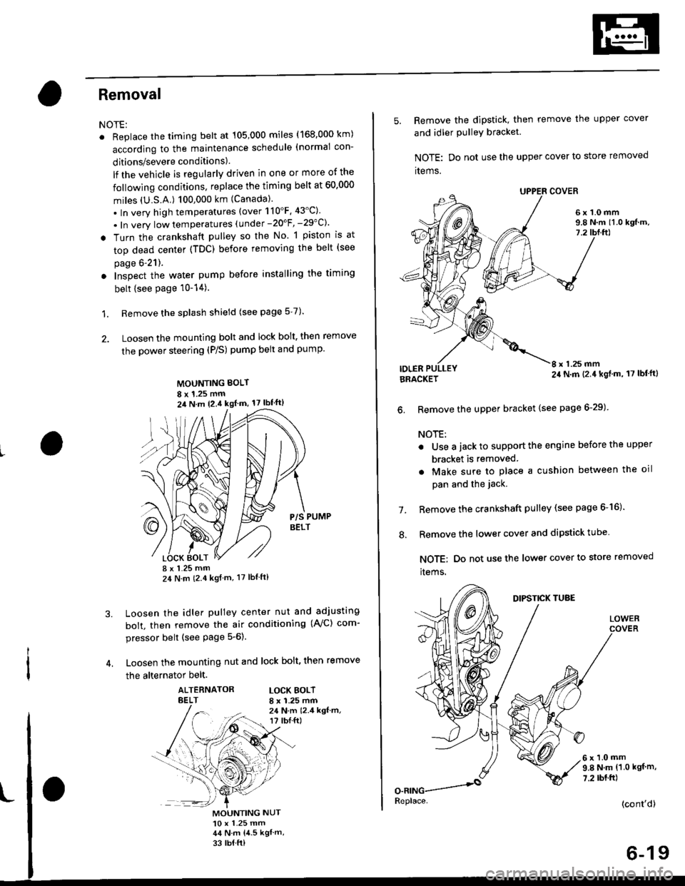
Removal
NOTE:
. Replace the timing belt at 105,000 miles (168.000 km)
according to the maintenance schedule (normal con-
ditions/severe conditions).
lf the vehicle is regularly driven in one or more of the
followlng conditions, replace the timing belt at 60.000
miles (U.S.A.) 100,000 km {Canada).
.In very high temperatures (over 110'F.43'C)
. In very low temperatures (under -20'F, -29"C)'
! Turn the crankshaft pulley so the No. 1 piston is at
top dead center (TDC) before removing the belt (see
page 6'21).
. Inspect the water pump before installing the timing
belt {see Page 10-14).
1. Remove the splash shield (see page 5-7).
2. Loosen the mounting bolt and lock bolt. then remove
the power steering (P/S) pump belt and pump
MOUNTING BOLT
8 x 1.25 mm2il N m 12.4 kgl m, 17 lbf'ft)
P/S PUMPBELT
I x 1.25 mm24 N m (2.4 kgf m, 17 lbt ft)
Loosen the idler pulley center nut and adjusting
bolt, then remove the air conditioning (AVC) com-
pressor belt (see Page 5-6).
Loosen the mounting nut and lock bolt, then remove
the alternator belt.
ALTERNATORBELTLOCK BOLTI x 1.25 mm24 N.m 12.4 kgf.m,r? tbI.ft)
3.
MOUNTING NUT10 x 1.25 mm44 N.m 14.5 kgl m,
33 rb{ ft)
5. Remove the dipstick, then remove the upper cover
and idler PulleY bracket
NOTE: Do not use the upper cover to store removed
items.
6x1.0mm9.8 N.m 11.0 kgf.m,7.2
IDLERI x 1.25 mm24 N.m (2.4 kgl.m, 17 lbf'ft)BRACKET
6. Remove the upper bracket {see page 6-29)
NOTE:
. Use a jack to support the engine before the upper
bracket is removed
. Make sure to place a cushion between the oil
pan and the jack.
Remove the crankshaft pulley (see page 6-16).
Remove the lower cover and dipstick tube
NOTE; Do not use the lower cover to store removed
items.
1.
.'.
DIPSTICK TUBE
LOWER
6x1.0mm9.8 N.m (1.0 kgf m,
7.2 rbt.ft)
(cont'd)
6-19
Replace.
Page 133 of 2189
Crankshaft Speed Fluctuation (CKF) Sensor
2.
3.
5.
Replacement
4.
1.
6x1.0mm'12 N.m {1.2 kgt.m,8.7 tbf.ft)
6. Installthe CKF sensor in reverse order of removal.
Remove the cylinder head cover.
NOTE: Refer to page 6-46 when installing.
Remove the crankshaft pulley (see page 6_16),
Remove the upper cover and dipstick/tube {seepage 6-19).
Remove the lower cover and idler pulley bracket(see page 6-19).
Disconnect the CKF sensor connector, then removethe CKF sensor.
CKF SENSORCONNECTOR
6-22
:(
I
Page 134 of 2189

Gylinder Head
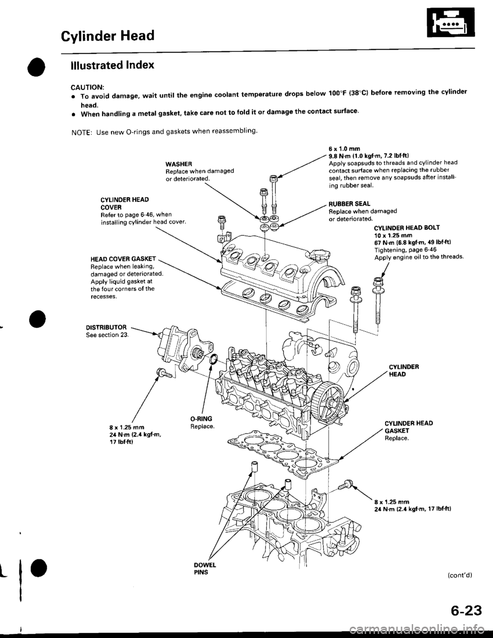
lllustrated Index
CAUTION:
. To avoid damage, wait until the engine coolant temperatule drops below 100"F (38'C) before removing the cylinder
head.
. When handling a metal gasket, take care not to fold it or damage the contact surface'
NOTEr Use new O-rings and gaskets when reassembling'
CYLINDER HEAD
COVERRefer to page 6 46, when
installing cylinder head cover.
WASHERReplace when damaged
or deteriorated.
O.RINGReplace.
6x1.0mm9.8 N.m 11.0 kgf.m, 7.2 lbfft)Apply soapsuds to threads and cylinder head
contact surface when replacing the rubber
seal, then temove any soapsuds after install
ing rubber seal.
RUBBER SEALReplace when damagedor deteriorated.
CYLINDER HEAD BOI-T
10 x 1.25 mm67 N.m 16.8 kgf m, a9 lbt'ft)
Tightening, Page 6-46
Apply engine oilto the threads.HEAD COVEB GASKETReplace when leaking,
damaged or deteriorated.Apply liquid gasket at
the four corners ol therecesses,
DISTRIBUTORSee section 23.
8 x 1 .25 mm24 N.m (2.4 kgf.m,17 tbt.ft)
CYLINDER HEADGASKETReplace.
8 x 1.25 mm24 N.m {2.4 kgf m, 17 lbf ftl
t(cont'd)
6-23
PINS
Page 135 of 2189
Cylinder Head
lllustrated Index (cont'dl
(-/) _.- E "or to reassembring, crean at the parts in sorvent, dry them and appry rubricant to anv contact oarts.
D16Y7 engine:
ROCK€R ARMASSEMBLYRemoval, page 6 30Inspection, page 6-35
8 x 1.25 mm20 N.m (2.0 kgt.m, 14 tbt.ftlApply engine oil to the
H
B
O-RINGReplace.
INTAKE VALVE SEALReplace.
VALVE SPRINGSEAT
INTAKE VALVEGUIDE
:a
ti
VALVE
SPRING RETAINER
EXHAUST VALVESEAL
VALVE SPRINGSEAT
EXHAUST VALVEGUIDErnspectron, page 6,39Beplacement, page 6 4lAeaming, page 6-43
8 x 1.25 mm37 N m (3.8 kgt m,27 tbtftlApply engine oiltothe threads.
INTAKE VALVERemoval, page 6-38lnstallation, page 6-43
Removal, page 6,27Warpage, page 6 40Valve seat reconditioning,page 6-40Installation, page 6-45
VALVE
t
t
t
CAMSHAFTnspectron, page 6-36
OIL CONTROLORIFICEClean.
KEEPERS
\
EXHAUST VALSPRING
c -A9-2.+
L
6x1.0mm12 N.m (1.2 kst.m, 8.7 tbf.ft)Apply engine oit to thethreads.
VALVE KEEPERS
SPRING RETAINER
INTAKE VALVESPRING
Page 136 of 2189
D16Y5 engine:
I x 1.25 mm20 N.m (2,0 kgf m, 14 lbf ft)
Apply engine oilto the
threads.ROCKEB ARMASSEMBLYFemoval, page 6-30
Inspection, Page 6-34
6x1.0mm12 N.m 11.2 kgf m, 8.7 lbf'ftl
Apply engine oilto the
threads.
VALVE KCEPERS
SPRING RETAINER
CAMSHAFTInspection, page 6-36
6x1.0mm12 N,m 11.28.7 tbf.ft)
WEC SOLENOIDVALVEBINTAKE VALVESPRING
INTAKE VALVE SEAL
Replace.
VALVE SPRINGSEAT
INTAKE VALVEGUIDE
CAMSHAFTPUL|'IY
VTEC SOLENOIDVALVE FILTERReplace.
OIL CONTROLORIFICEClean.
VALVE
SPRING RETAINEB
EXHAUST V
SPRING
VE
EXHAUST VALVE
SEALt"o'""".uoau,
SEATReplace.
GUIDEInspection, page 6-39Replacement, Page 6-41
Reaming, page 6-43EXHAUSTVALVEOIL SEALReplace.
HEAD
8 x 1.25 mm
37 N.m 13.8 kgf.m,
27 tbf.frlApply engine oiltothe lhreads.
(cont'd)
6-25
INTAKE VALVERemoval, page 6 38
Installalion, Page 6 43Removal, page 6-27Warpage, Page 6 40
Valve seat reconditioning'page 6-40lnstallation, page 6_45
Page 137 of 2189

Cylinder Head
lllustrated Index (cont'dl
VALVE KEEPERS
SPRING RETAINER
INTAKE VALVE
VTEC SOLENOIDVALVE FILTEBReplace.
OIL CONTROLORIFICEClean.
INTAKE VALVE SEALReplace.VALVE SPRINGSEAT
INTAKE VAI.VEGUIOE
CAMSHAFTPULLEY
I
I
VALVE KEEPERS
SPRING RET
EXHAUST VALVESPRING
@
EXHAUST VALVESEALReplace.
8 x 1.25 mm37 N.m 13.8 kgt m,27 tbfitlApply engine oiltothe threads.
EXHAUSTVALVE
-vp
e,.io"o reassembring, crean at the parts in sorvent, dry them and appry rubricant to any contact parts.
D16Y8 engine:
LOST MOTIONASSEMgLY
ROCKER ARMASSEMBLYRemoval, page 6 30Inspection, page 6-34
5xl.0mm12 N.m {1.28.7 tbf.ft)
VALVE SPRINGSEATEXHAUSTVALVE O.RINGGUIDE Replace.Inspection, page 6 39Replacement, page 6 41Reaming, page 6 43
LOST MOTIONASSEMBLYHOLDER
INTAKE VALVEBemoval, page 6 38Installation, page 6 43
20 N.m 12.0 kgl.m, 14 tbf.ft)Apply engine oit to thethreads.
\
\
s9illl
CAMSHAFTInspection, page 6-36
OIL SEALBeplace.
CYLINDER HEADRemoval, page 6 27Warpage, page 6-40Valve seat reconditioning,page 6 40Installation, page 6-45
6x1.0mm12 N.m (1.2 kgt.m,8.7 lbf.ftlApply engine oil to thethreads,
Page 138 of 2189

Removal
Engine removal is not required for this procedure
!!!s@ Make sure iacks and salety stands are
f ta"eata"ea propetty and hoist brackets are attached to the
correct positions on the engine.
CAUTION:
. Use tender covels to avoid damaging painted sul-
faces.
o To avoid damage, unplug the wiling connectors
carefully while holding the connector portion to
avoid damage.
. To avoid damaging the cylinder head, wait until the
engine coolant temperature drops below 100"F
{38"C} before loossning the tetaining bolts.
NOTE:
o Mark all wiring and hoses to avoid misconnectlon
Also, be sure that they do not contact other wiring or
hoses, or interfere with other parts.
. Inspect the timing belt before removing the cylinder
h ead.
. Turnthe crankshaft pu lley so that the No. lpistonisat
top dead center (see Page 6-21)
'1. Disconnect the negative terminal from the battery'
Drain the engine coolant (see page'10-7).
a Remove the radiator cap to speed draining.
Remove the intake air duct and air cleaner housing
(see page 5 3).
Remove the mounting bolt and lock bolt. then
remove the power steering (P/S) pump belt and
pump (see page 5'5).
Loosen the idler pulley center nut and adjusting
bolt' then remove the air conditioning (A'lc) com-
pressor belt (see Page 5-6).
Loosen the mounting nut and lock bolt. then
remove the alternator belt (see page 6-19).
Remove the P/S pump bracket (see page 5-12).
3.
4.
2.
6.
1.
8. Remove the throttle cable by loosening the locknut,
then slip the cable end out of the throttle linkage
NOTE:
. Take care not to bend the cable when removing it
Always replace any kinked cable with a new one
. Adjust the throttle cable when installing (see sec-
tion 1 1).
D16Y7 engine:
Dl6Y5, Dl6Y8 engines:
THFOTTLECABLE
(cont'd)
6-27
LOCKNUT
CABLE