Page 116 of 2189

(From page 6'4)
Test the VTEC Solenoid Valve:1. Turn the ignition switch OFF.2. Disconnect the wEC solenoidvalve 1P connector.3. Attach the battery positave
terminal to the VTEC solenoidvalve terminal.4. Start the engine and checkthe oil pressure at enginespeed of 5,000 rpm.
Inspect lhe VTEC solonoid valve
lsee p6ge m).ls the pressure above 390 kPa(4.0 kgtcm'�,57 psi)?
Test the VTEC Pressure Switch:With the battery positive terminalconnected to the VTEC solenoidvalve, measure voltage betweenthe ECM/PCM connector terminal'96 - 98: Cl5,'99 - 00: C10 andbody ground.
ls there battery voltage above5,000 rpm?
T6st the VTEC Solenoid Valvewire:1. Turn the ignition switch OFF.2. Check for continuity betweenthe VTEC solenoid valve 1Pconnector terminal and theECM/PCM connector terminal'96 - 98: A8, '99 00r B'12.
Repair open in the wire betweenthe ECM/PCM ('96 - 98: A8, '99 -
0o: 8l2l and VTEC solenoid v.lv6connoc{or.
Test the VTEC Solenoid Valve
Check for continuity between theVTEC solenoid valve 1P connectorterminal €nd body ground.
ReDair 3hort in the wire betweenthe ECM/FCM ('96 - 98: A.8, '99 -
0O: Bl2l and VTEC aolenoid valveconnectot,
ls there continuity?
Substitute a known-good ECM/PCM and recheck. lf symptom/indication goes away, replacethe original ECM/PCM.
VTEC SOLENOID VALVE1P CONNECTOR
Terminalside ofmale terminal
ECM/PCM CONNECTOR C {31P}
'99 - 00:'96 - 98:
CONNECTOR
'99 - 00:
VTEC SOLENOIDVALVE
ECM/PCM CONNECTORB {25Pt1P CONNECTOR'96 - 98:
VTEC SOLENOIDVALVE
ECM/PCM CONNECTOR
A {32P1
VTS{GRN/YEL)
wire side o{ femaleterminals
wire side oI temaleterminals
VTM
Page 117 of 2189
VTEC Solenoid Valve
Inspection
1.
6x1.0mm12 N.m 11.2 kgf.m,8.7 lbtft)
Disconnect the 1P connector from the VTEC sole-noid valve.
Measure resistance between the terminal and bodyground.
Resistance: l4 - 30 O
lf the resistance is within specifications, remove theVTEC solenoid valve assembly from the cylinder
head, and check the VTEC solenoid valve filter for
cloggrng.
. lf there is clogging, replace the engine oil filterand the engine oil.
VTEC SOLENOID VAI-VE ASSEMBLY
6-6
(
4. lf the filter is not clogged, push the VTEC solenoidvalve with your finger and check its movement.
. lf the VTEC solenoid valve is normal. check the
engane oil pressure.
6x1.0mm12 N.m {1.2 kgt.m,8.7lbf.ft)
I
.(
I
\
;
..l'
Page 118 of 2189

VTEC Rocker Arms
2.
Manual Inspection (D16Y5 engine)
3.
1.
4.
Set the No. 1 piston at TDC.
Remove the cylinder head cover.
NOTE: Refer to page 6-46 when installing the cylin-
der head cover.
Move the intake secondary rocker arm on the No. 'l
cylinder manually.
Check that the intake secondary rocker arm moves
independently of the primary intake rocker arm,
SECoNDARY PtROCKER ARM. Push and pull.
Check the intake secondary
cylinder at TDC.
rocker arm of each
a lf the intake secondary rocker arm does not move,
remove the primary and secondary intake rocker
arms as an assembly and check that the pistons in
the secondary and primary rocker arms move
smoothly.
a lf any rocker arm needs replacing, replace the pri-
mary and secondary rocker arms as an assembly.
PRIMARY ROCKER ARM
4.
Manual Inspection (D16YB engine)
1.Set the No. 1 piston at TDC.
Remove the cylinder head cover.
NOTE: Reter to page 6-46 when installing the cylin-
der head cover.
Push the intake mid rocker arm on the No. 1 cylin-
der manually.
Check that the intake mid rocker arm moves indepen-
dently of the primary and secondary intake rocker
arms.
MID ROCKERARM
Check the intake mid rocker arm of each cylinder at
TDC,
lf the intake mid rocker arm does not move.
remove the mid, primary and secondary intake
rocker arms as an assembly and check that the pis-
tons in the mid and primary rocker arms move
smoothly.
lf any rocker arm needs replacing, replace the
primary, mid, and secondary rocker arms as an
assemory.
5,
6-7
Page 120 of 2189

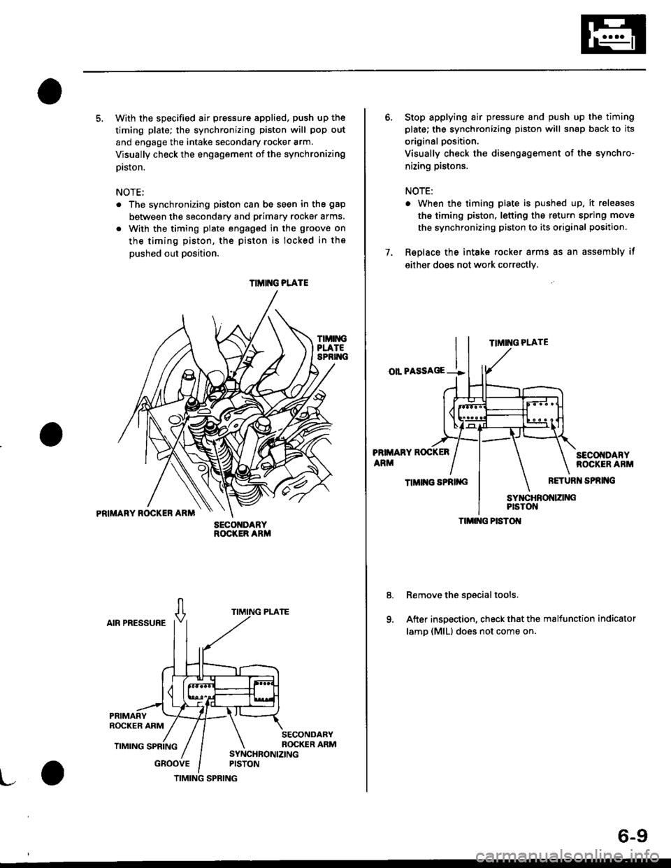
5. With the specified air pressure appli€d, push up the
timing plate; the synchronizing piston will pop out
and engage the intake secondary rocker arm.
Visually check the engagement of the synchronizing
prston.
NOTE;
The synchronizing piston can be seen in the gap
between the secondary and primary rocker arms,
With the timing plate engaged in the groove on
the timing piston, the piston is locked in the
oushed out Dosition.
TIMIiIGPLATESPRIT{C
PRIMARY ROCKER ARM
AIR PRESSURE
GROOVE
SECO DARYROCKER ARM
TIMIT{G PLATE
TIMING SPRING
6-9
6. Stop applying air pressure and push up the timing
plate; the synchronizing piston will snap back to its
original position.
Visually check the disengagement of the synchro-
nizing pistons.
NOTE:
. When the timing plate is pushed up, it releases
the timing piston, letting the return spring move
the synchronizing piston to its original position.
7. Replace the intake rocker arms as an assembly if
either does not work correctly,
TIMING PLATE
oll PASSAGE --!
PRIMARY ROCKER
ARMSECOI{DARYROCKER ARM
TIMII{G SPRII{GRETURI{ SPRING
Remove the spscial tools.
After inspection, check that the malfunction indicator
lamp (MlLl does not come on.
TIMI G PISTOI{
Page 122 of 2189
4. Loosen the regulator valve on the valve inspection
tool and apply the specified air pressure.
Specified Air Pressure:
250 kPa {2.5 kgf/cm'�, 36 psil
PRIMARY ROCKERARM
SYNCHRONIZING SYNCHRONIZINGPISTON A PISTON B
Make sure that the intake primary and secondary
rocker arms are mechanically connected by the piston
and that the mid rocker arm does not move when
oushed manuallY.
5.
MID ROCKER SECONDARYARM ROCKER ARM
SECONDARYROCKER ARM
lf any intake mid rocker arm moves independently of
the primary and secondary rocker arms, replace the
rocker arms as a set.t
1.
8.
9.
Remove the special tools.
Use a 10 mm diameter rod to depress each lost
motion assembly through its full movement.
Replace any lost motion assembly that does move
smoothly.
After inspection, check that the MIL does not come
on.
ASSEMBLY
6-11
Page 125 of 2189

Valve Seals
Replacement (Cylinder head removal not requiredl
NOTE: Cylinder head removal is not required in thisprocedure.
The procedure shown below applies when using the in-
car valve spring compressor (Snap-on YA884S withY48845 - 2 A7/8" attachment).
!@@ Alway wear approved eye protection whenusing ihe in-cai valve spring compressor.
1. Turn the crankshaft so that the No. I and the No. 4pistons are at top dead center (TDC).
2. Remove the cylinder head cover and the rocker arm
assembly.
NOTE:
. Refer to page 6-30 for rocker arm assembly
removat.
. When removing or installing the rocker armassembly, do not remove the camshaft holder
bolts. The bolts will keep the holders, springs
and rocker arms on the shaft.
. Refer to page 6-46 when installing the cylinder
head cover.
Remove the fuel injectors and the wire harness.
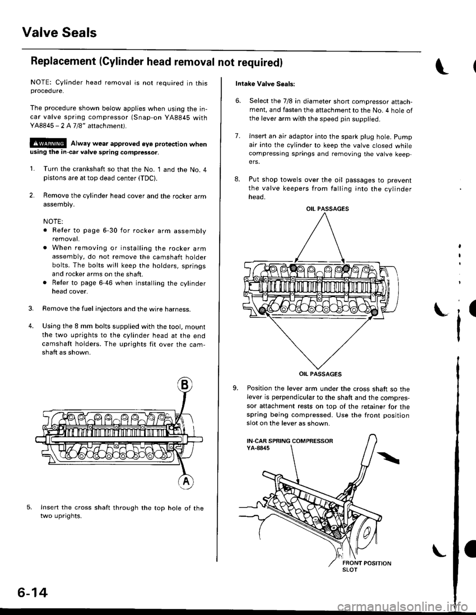
Using the 8 mm bolts supplied with the tool. mount
the two uprights to the cylinder head at the end
camshaft holders. The uprights fit over the cam-
shaft as shown.
lnsert the cross shaft through the top hole of thetwo uprights.
3.
4.
6-14
Intake Valve Seals:
6. Select the 7/8 in diameter short compressor attach-ment, and fasten the attachment to the No. 4 hole of
the leve. arm with the speed pin supplied.
8.
7.lnsert an air adapto. into the spark plug hole. pump
air into the cylinder to keep the valve closed whilecompressing springs and removing the valve keepers.
Put shop towels over the oil passages to prevent
the valve keepers from falling into the cylinder
neao.
OIL PASSAGES
Position the lever arm under the cross shaft so thelever is perpendicular to the shaft and the compres-
sor attachment rests on top of the retainer for thespring being compressed. Use the front position
slot on the lever as shown.
,
I
i'
OIL PASSAGES
IN-CAR SPRING COMPRESSOR
SLOT
Page 127 of 2189
Crankshaft Pulley and Pulley Bolt
Replacement
When installing and tightening the pulley. follow theprocedure below,
Clean, remove any oil, and lubricate points shown
below.
O: Clean
x: Bemove any oil
a: Lubricate
TIMING BELTGUIOE PLATE
Crankhaft pulley bolt size and torque value:
14 x 1.25 mm
20 N.m {2.0 kgl.m, 14 lbf.ft) + 90'
NOTE: Do not use an impact wrench when installing.
HOI.I'ER HANDTI07JAB - 001020A
HOLDER ATTACHMENT. 50 mm07NAB - ootoilllA
S(rc(ET, 17 mm07JAA-lxtl010A or{Co.nm.rci.lly .v.il.bl.}
CRANKSHAFT
6-16
'1.Tighten the pulley bolt to the specified torque.
Torque: 20 N.m {2.0 kgf.m, 14 lbf'ft}
Use I felt tip pen to mark the pulley bolt head andwasher.
EMBOSSING MARKS
3. Tighten the pulley bolt an additional 90".
EMBOSSING MABKMARKING
\
MARKING
MARKING
I
Page 128 of 2189

Timing Belt
Illustrated lndex
NOTE:
. Refer to page 6-20 for how to position the crankshaft and pulley before installing the belt.
. Mark the direction of rotation on the belt before removing.
a Do not use the upper cover and lower cover for storing removed items,
. Clean the upper cover and lower cover before installing.
. Replace the ca mshaft seals and cra n kshaft sea ls if there is oil leakage.
. Refer to page 6-16 before installing the timing belt.
CYLINDER HEADCOVERReler to page 6-46when installing.
HEAD COVEB GASKETReplaco when l6akin9,domaged or deteriorated.Apply liquid gasket at
th€ lour corners of thetecessos.
d
@
TIMING BELTInspection, page 6-18Adjustment, page 6-18Removal, page 6-19Installation. page 6-20
I x 1.25 mm3t N.m {3.8 kgf'm, 27 lbfftl
Apply engine oilto the bolt
thleads.
CRANKSHAFT SPEED FI.UCTUATION
lcr(Fl sENsoRReplacement, Page 6-22
UPPER COVEB
lnstallwithsurface facing in.
TIMING BELTDRIVE PULLEYReplacement, page 6_16
6x1.0mm9.8 N'm 11.0 kgt m,7.2 tbf.ft)NUBBER SEALSReplace when damagedor deledorated.
LOWER COVER
FUBBERPLUG
CRANKSHAFT PULLEYReplacement, page 6'16
PULLEY BOLTlil x 1.25 mm20 N.m 12.0 kgt.m,14 lbt'ft) + 90"Replacement, page 6'16Do not us6 an impactwrench when installing.
x 1.0 mmBOLT o-RING10 x 1,25 mm Reolace.14 N.m {,1.5 kgt m, 33 lbt ftl
6x1.0mmt2 N.m 11.2 kgf'm,8.7 tbt f0
9.E N'm (1.0 kgt.m,?.2 tbf.ftl\.-,o
6-17