1996 HONDA CIVIC fuel gauge
[x] Cancel search: fuel gaugePage 565 of 2189
Emission Gontrol System
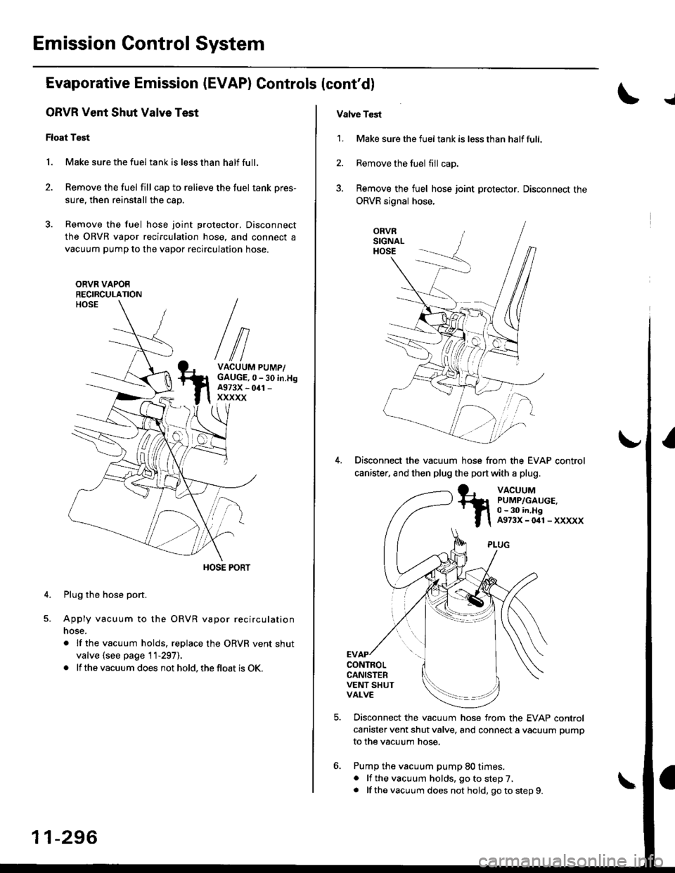
Evaporative Emission (EVAP) Controls (cont'dl
ORVR Vent Shut Valve Test
Float Test
1. Make sure the fuel tank is less than half full.
2. Remove the fuel fill cap to relieve the fuel tank pres-
sure, then reinstall the cap.
3. Remove the fuel hose joint protector. Disconnect
the ORVR vapor recirculation hose, and connect a
vacuum pump to the vapor recirculation hose.
ORVR VAPOERECIRCULATION
VACUUM PUMP/GAUGE,0 - 30 in.H9A973X - 041 -
xxxxx
Plug the hose port.
Apply vacuum to the ORVR vapor recirculation
nose.
. lf the vacuum holds, replace the ORVR vent shut
valve {see page 11-297).
. lf the vacuum does not hold, the float is OK.
4.
11-296
Vatve Tcst
1. Make sure the fueltank is lessthan halffull.
2. Remove the fuel fill cap.
3. Remove the fuel hose joint protector. Disconnect the
ORVR signal hose.
ORVRSIGNALHOSE
Disconnect the vacuum hose from the EVAP control
canister. and then plug the port with a plug.
VACUUMPUMP/GAUGE,0 - 30 in,HgA973X-041-XXXXX
CONTROLCANISTERVENT SHUTVALVE
Disconnect the vacuum hose from the EVAP control
canister vent shut valve, and connect a vacuum pump
to the vacuum hose,
Pump the vacuum pump 80 times.. lf the vacuum holds, go to step 7,. lf thevacuum does not hold, goto step9.
Page 566 of 2189

\
\
7. Connect a second vacuum pump to the OBVR signal
nose.
VACUUM PUMP/GAUGE.0 - 30 in.HgA973X - 041 -
xxxxx
Apply vacuum (1 pump) to the ORVR signal hose,
then check the vacuum on the pump in step 6.
. lf the vacuum holds, replace the ORVR vent shut
valve.
. lf the vacuum is released, the ORVR vent shut
valve is OK.
Disconnect the ORVR quick disconnect from the EVAP
canister, then plug the port on the canister.
Reapply vacuum (80 pumps).
. lf the vacuum holds, reDlace the ORVR vent shut
valve,
. lf the vacuum does not hold, inspect the EVAP can-
ister vent shut valve O-ring. lf the O-ring is OK,
replace the EVAP canister and repeat step 4.
\
I
11-297
ORVR Vent Shut Valve Replacement
1. Remove the fuel tank (see page 1 1-242).
2. Remove the ORVR vent shut valve from the fuel tank.
3. lnstall oarts in the reverse order of removal.
Page 726 of 2189
Troubleshootin g Procedures
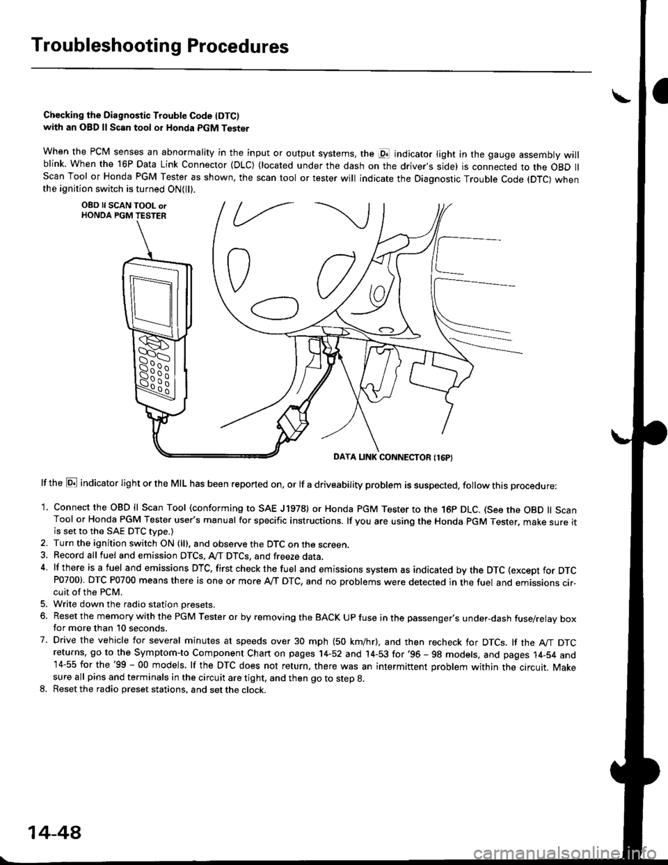
Chccking the Diagnostic Trouble Code IDTC)with an OBD ll Scan tool or Honda PGM Tester
when the PCM senses an abnormality in the input or output systems, the pl indicator light in the gauge assembly willblink. When the 16P Data Link Connector (DLC) (located under the dash on the driver,s side) is connected to the OBD llScan Tool or Honda PGM Tester as shown, the scan tool or tester will indicate the Diagnostic Trouble Code (DTC) whenthe ignition switch is turned ON{ll).
lf the El indicator light or the MIL has been reported on, or lf a driveability problem is suspected, follow this procedure:
1. Connect the OBD ll Scan Tool (conforming to SAE J19781 or Honda PGM Tester to rhe 16p DLC. (See the OBD ll ScanTool or Honda PGM Tester user's manual for specific instructions. lf you are using the Honda PGM Tester, make sure itis set to the SAE DTC type.)
2. Turn the ignition switch ON (lll, and observe the DTC on the screen,3, Record all fuel and emission DTCS, A/T DTCS, and freeze data.4 lf there is a fuel and emissions DTC, first checkthe fuel and emissions system as indicated bythe DTC (except for DTCP0700). DTC P0700 means there is one or more A,/T DTC, and no problems were detected in the fuel and emissions cir-cuit of the PCM.
5. Write down the radio station oresets.
6. Reset the memory with the PGM Tester or by removing the BACK UP fuse in the passenger's under-dash fuse/relay boxfor more than 10 seconds.
7. Drive the vehicle for several minutes at speeds over 30 mph (50 km/hr), and then recheck for DTCS. lf the A"/T DTCreturns, go to the Symptom-to Component Chart on pages 14-52 and 14-53 for'96 - 98 models, and pages 14-54 and14-55 for the'99 - 00 models, lf the DTC does not return, there was an intermittent problem within the circuit. Makesure all pins and terminals in the circuit are tight, and then go to step g.
8. Reset the radio preset stations, and set the clock.
OBD ll SCAN TOOL orHONDA PGM TESTER
DAYA LINK CONNECTOR {16P}
14-44
Page 1471 of 2189

l'f .
Electrical
Special Toofs .,....................,23-2
Troubleshooting
Tips and Precautions ..............,.................... . 23-3
Five-step Troubleshooting .............. ......... . . 23-5
wire color codes ..........,23-5
Schematic Symbols ........,................... . . .. .... 23-6
Relay and Control Unit Locations
Engine Compartment ...,..................... ... .. . 23'7
Dashboard ......................23-8
Dashboard/Door ......... 23-12*Airbags ................. ....... Section 24
Air Conditioning ......... Section 21
Aftelnator ..........."""" """ 23-112
Anti-lock Brake System {ABS) Section 19*A/T Gear Position Indicator .....................,. .... ... 23-149
Automatic Transmission Svstem .... . ....... Section 14
Batterv ......... . . . ... ...... .......23-91
Blower controls .. . ... Section 2l
Charging System ....'...........23'112
Connector ldentilication and Wire Harness
Routing .................. ......23'13
Cruise Control ............,........23-240
Dash Lights Brightness Controller ............. ....... 23-180
Fan controfs "" 23'126
Fuel PumD ........ . ........ section 11
Fuses/Refay ...............,..,,.. 23'62
PGM-FI Control System ......................,....... Section 1 1
*Gauges
Circuit Diagram ....,.,.......23-131
Fuef Gauge ...........'.'.......23-142
Gauge/lndicator .. . .. 23-129
Ground Distribution .. . 23-75
Heatei controls .. . ..... Section 21*Horn................. ...............23-196
*tgnition Switch ....................23-89
lgnition System .......,.... 23-102
*lntegrated Control Unit ....................................... 23-156
fnterlock System ,........ . . , ,23-144
Lighting System . . . .. ......... 23-161
Lights, Exterior
Back-up Lights ..'............23'171
Brake Lights .................. 23'174
Daytime Bunning Lights (Canadal ............... 23'166
Front Parking Lights ......,................ .'. .......... 23-167
Front Turn Signal Lights .......... . . ............ ..,.23-167
Headtights ....".'....-... ..... 23'167
High Mount Brake Light ...................... ... .23'179
License Plate Lights ...... 23'176
Taitfights ................ .......23'171
lnterior Lights ..-.......,, . 23-142
Moonroof ..,.................,........ 23-235
Power Distribution ....... . . .23-61
Power Door Locks .......,,,. .23'251
Power Mirrors ,..............,.,...23'206
Power Relays ....... . ...... . . .. 23-86
Power Windows ............,,....23-220
Rear Window Defogger .......................... . . ... . . 23-2OO
Spark Plugs . ..... . ........ .....23-111
Slarting System ................23-93*stereo Sound Svstem ,................. ..... ... . ... ,.,.,,23'147'Supplemental Restraint System (SRS) ... . Section 24
Turn Signal/Hazard Flasher System .......'.'....-... 23-173
*Undel-dash Fuse/Relay Box ............,.................. 23-85
vehicfe soeed sensor (VSSI """" ""' 23-140+Wipers/Washers .........,.,.,...23-214
NOTE: Unless otherwise specified, references to auto-
matic transmission (Mf) in this section include the CVT.
Page 1472 of 2189
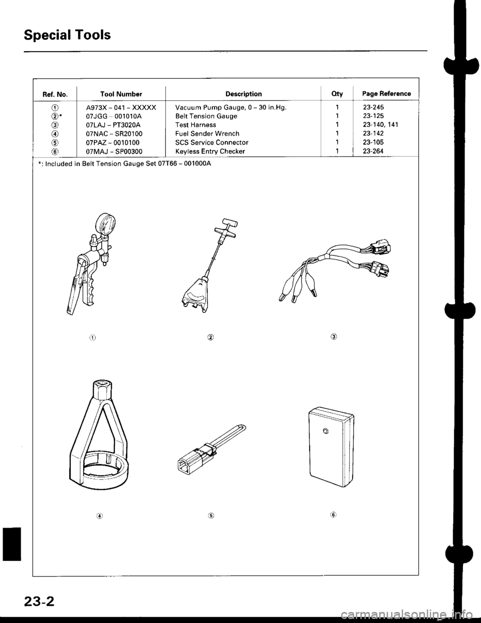
Special Tools
Ref. No. Tool NumberDescriptionOty Page Reference
O)
@-
o
@
o
tol
A973X_041 _XXXXX
07JGG 00l0l0A
OTLAJ - PT3O2OA
07NAC - SR20100
07PM - 0010r 00
07MAJ - SP00300
Vacuum Pump Gauge, 0 - 30 in.Hg.
Belt Tension Gauge
Test Harness
Fuel Sender Wrench
SCS Service Connector
Keyless Entry Checker
1
1'I
1
1
1
23-245
23-140,141
23-142
23-105
23-264
': Included in Belt Tension Gauge Set 07T66 - 0010004
or/4,
(!
23-2
Page 1510 of 2189
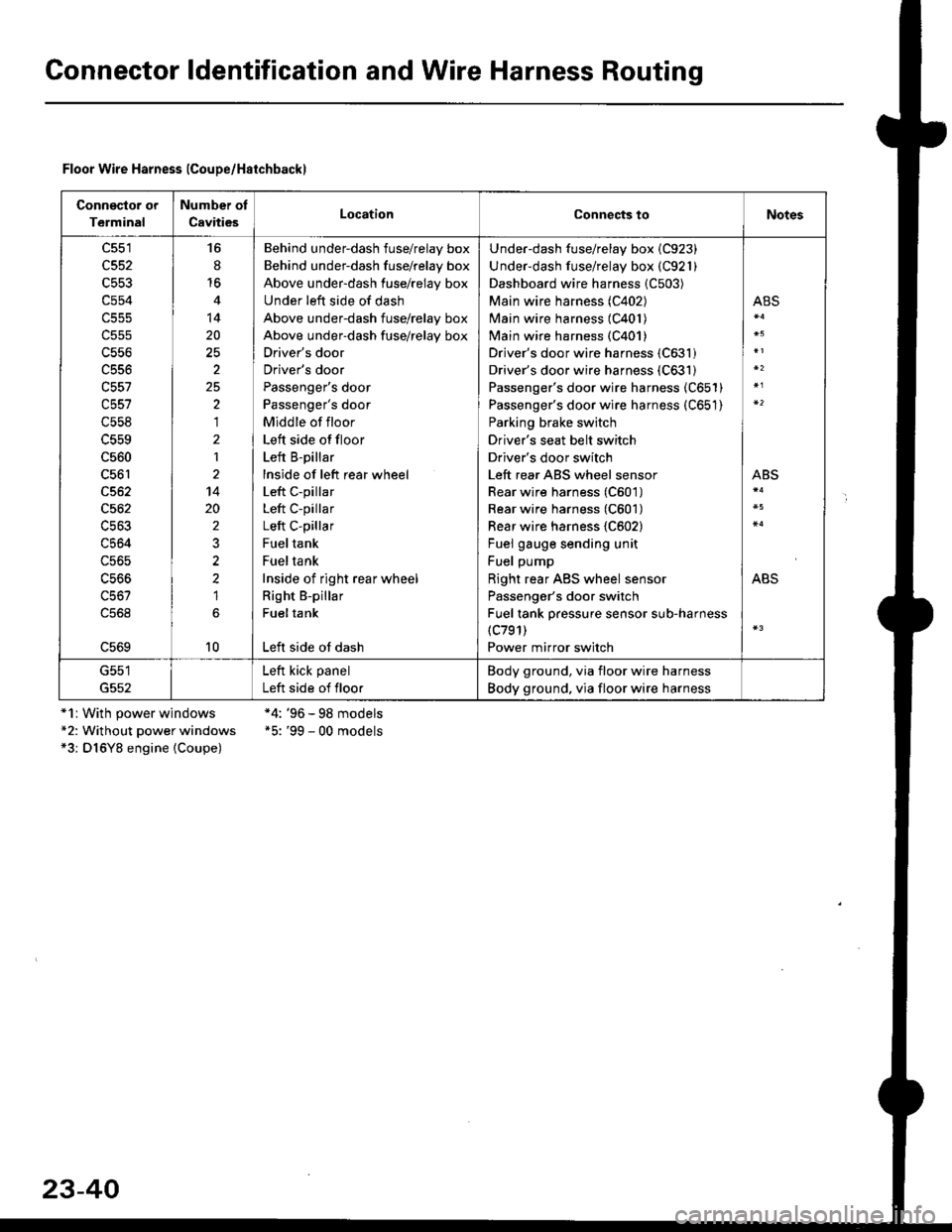
Gonnector ldentification and Wire Harness Routing
Floor Wire Harness lCoupe/Haichbackl
Connsclor or
Terminal
Number of
CavitiesLocationConnects toNotes
c551
c552
c553
c554
c556
c556
c557
c558
c560
c561
c562
c564
c56s
16
8'16
14
20
2
25,)
,I
2
1
14
20
2
2?
1
10
Behind underdash fuse/relay box
Behind under-dash fuse/relay box
Above under-dash fuse/relay box
Under left side of dash
Above under-dash fuse/relay box
Above under-dash fuse/relay box
Driver's door
Driver's door
Passenger's door
Passenger's door
Middle of floor
Left side offloor
Left B-pillar
lnside of left rear wheel
Left c-pillar
Left C-pillar
Left C-pillar
Fueltank
Fueltank
Inside of right rear wheel
Right B-pillar
Fueltank
Left side ot dash
Under-dash fuse/relay box {C923)
Under-dash fuse/relay box (C921)
Dashboard wire harness {C503)
Main wire harness (C402)
Main wire harness (C401)
Main wire harness {C401)
Driver's door wire harness (C631)
Driver's door wire harness (C631)
Passenger's door wire harness (C651)
Passenger's door wire harness (C651)
Parking brake switch
Driver's seat belt switch
Driver's door switch
Left rear ABS wheel sensor
Rear wire harness (C601)
Rear wire harness (C601)
Rear wire harness {C602}
Fuel gauge sending unit
Fuel pump
Right rear ABS wheel sensor
Passenger's door switch
Fuel tank pressure sensor sub-harness(c791)
Power mirror switch
ABS
ABS
ABS
G551
G552
Left kick panel
Left side of floor
Body ground, via floor wire harness
Body ground. via floor wire harness
*1r With power windows*2: Without power windows*3: D16Y8 engine {Coupe)
*4: '96 - 98 models*5: '99 - 00 models
23-40
Page 1512 of 2189
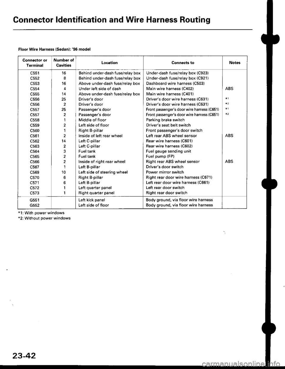
Gonnector ldentification and Wire Harness Routing
Connector ol
Terminal
Number of
CavitiesLocationConnects toNotes
c553
c554
c556
c557
c557
c558
c559
c560
c561
c562
c563
c564
c565
c566
c567
L5bY
c570
c511
c572
c513
6
14
25
2
25
'|
1
2't4
1'10
6
6
I
1
Behind underdash fuse/relay box
Behind under-dash fuse/relay box
Above under-dash fuse/relay box
Under left side of dash
Above under-dash fuse/relay box
Drlver's door
Driver's door
Passenger's door
Passenger's door
Middle of floor
Left side of floor
Right B-pillar
lnside of left rear wheel
Left C-pillar
Left C-pillar
Fuel tank
Fuel tank
Inside of right rear wheel
Left B-pillar
Left side of steering wheel
Right B-pillar
Left B-pillar
Left quarter panel
Right quarter panel
Under-dash fuse/relay box {C923)
Under-dash fuse/relay box (C921)
Dashboard wire harness (C503)
Main wire harness (C402)
Main wire harness (C401)
Driver's door wire harness (C631)
Driver's door wire harness (C631)
Front passenger's doorwire harness (C651)
Front passenge/s doorwire harness (C651)
Parking brake switch
Driver's seat belt switch
Front passenger's door switch
Left rear ABS wheel sensor
Rear wire harness (C601)
Rear wire harness (C602)
Fuel gauge sending unit
Fuel pump {FP)
Right rear ABS wheel sensor
Driver's door switch
Power mirror switch
Right rear door wire harness (C671)
Left rear door wire harness (C661)
Left rear door switch
Right rear door switch
ABS
ABS
ABS
G552
Left kick panel
Left side of floor
Body ground, via floor wire harness
Body ground, via floor wire harness
Floor Wire Harness lSedanl: '96 model
*l:With power windows*2; Without power windows
23-42
Page 1514 of 2189
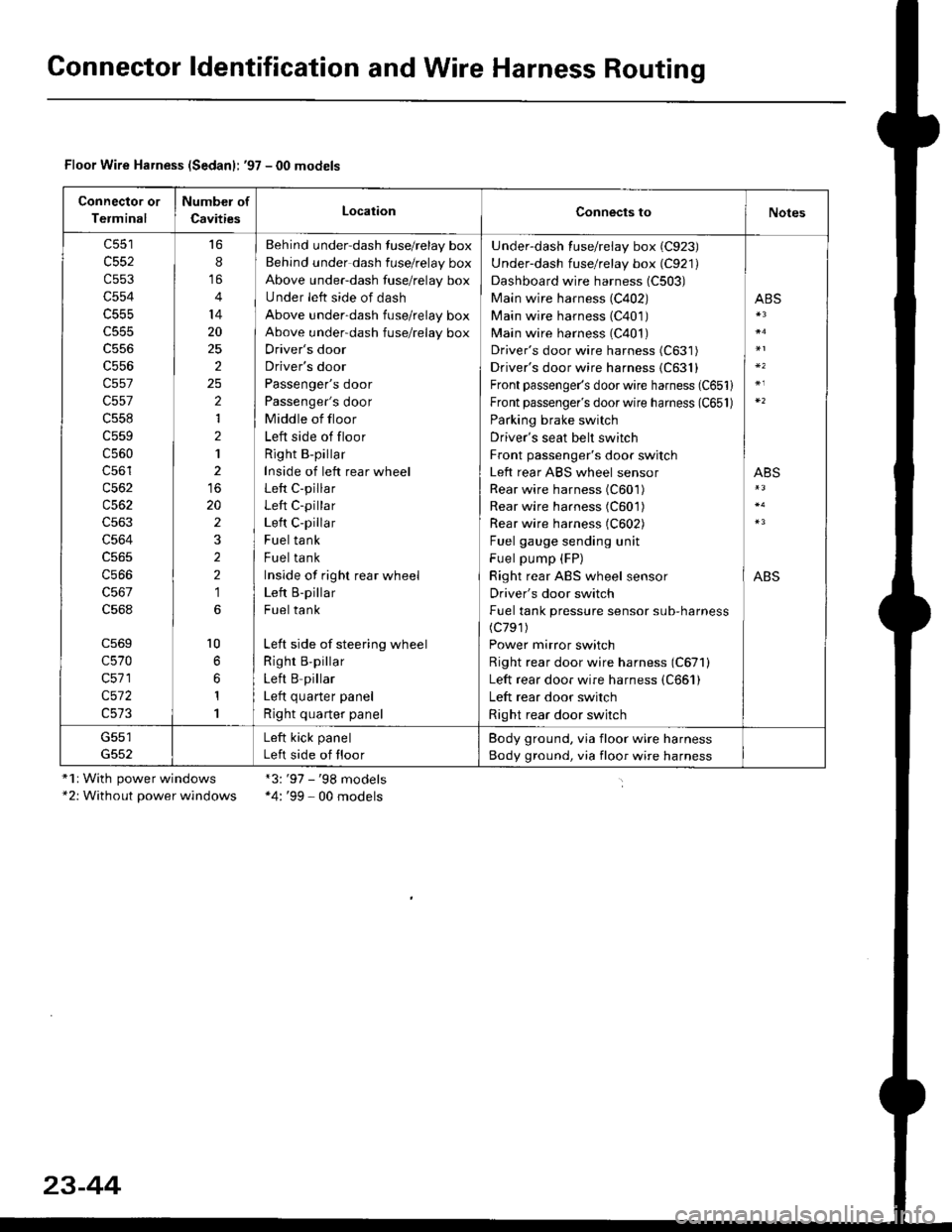
Gonnector ldentification and Wire Harness Routing
Floor Wire Harness (Sedanl: '97 - 00 models
Connector or
Terminal
Number of
CavitiesLocationConnects toNotes
c552
c553
c554
c555
c556
c557
c557
c558
c559
c560
c56'l
c562
c563
c564
c566
c568
c569
c570
c571
c572
16
8
14
20
25
2
2
1
2
1
20
2
2
2
1
l0
1
1
Behind under-dash fuse/relay box
Behind under dash fuse/relay box
Above under-dash fuse/relay box
Under left side of dash
Above under-dash fuse/relay box
Above under-dash fuse/relay box
Driver's door
Driver's door
Passenger's door
Passenger's door
Middle of floor
Left side of floor
Right B-pillar
Inside of left rear wheel
Left C-pillar
Left C-pillar
Left C-pillar
Fuel tank
Fuel tank
Inside of righr rear wheel
Left B-pillar
Fuel tank
Left side of steering wheel
Righr B,pillar
Left B pillar
I ofr ^,,.riar ^.^al
Right quarter panel
Under-dash fuse/relay box (C923)
Under-dash fuse/relay box (C921)
Dashboard wire harness (C503)
Main wire harness (C402)
Main wire harness (C401)
Main wire harness (C401)
Driver's door wire harness (C631)
Driver's door wire harness {C631}
Front passenger's door wire harness (C651)
Front passenger's door wire harness (C651)
Parking brake switch
Driver's seat belt switch
Front passenger's door switch
Left rear ABS wheel sensor
Rear wire harness (C601)
Rear wire harness (C601)
Rear wire harness (C602)
Fuel gauge sending unit
Fuel pump (FP)
Right rear ABS wheel sensor
Driver's door switch
Fuel tank pressure sensor sub-harness(c791)
Power mirror switch
Right rear door wire harness (C671)
Left rear door wire harness (C661)
Left rear door switch
Right rear door switch
ABS
ABS
ABS
G551Left kick panel
Left side of floor
Body ground, via floor wire harness
Body ground, via floor wire harness
"1r With power windows*2: Without power windows
*3:'97 - '98 models*4: '99 - 00 models
23-44