Page 1303 of 2189
Seats and Seat Belts
Component Location Index
2Dl3Dl1Dl
SHOULDER ANCHOR
ADJUSTER (4D)
(see Page 20-85i
FRONT SEAT BELT
Replacement, Pages 20 85,86
Inspection, Page 20-91
FRONT SEARemoval, Page 20'74
Replacement, Page 20 75
Harness Wiring and Recline
Cable Locations, Page 20-77
Seat Cover RePlacemenl, Page 2O'77
3D:
BEAR SEAT BELTReplacement, Page 20'89Inspection, page 20-91
REAB SEAT BELT (2DI4DI
Replacement, page 20-88
lnspection, page 20-91REAR SEAT EELT BUCKLE/CENTER BELT TONGUE (2DI4DI
(see p6ge 20'90)
REAR SEAT t2Dl4DlRemoval, pages 20-79, 8'l
Seat-back Latch Replacement, page 20-82
Seat Cover RePlacement, Page 20-83
FRONT SEATBELT BUCKLES{see page 20-87)
REAR SEAT BELT BUCKLE/
CENTER BELT TONGUE(see Page 20'90)
REAR SEATRemoval, page 20 80
Seat back Latch Replacement, page 20-8?
Seat Cover RePlacement, Page 20_83
20-73
Page 1309 of 2189
Rear Seat
Removal
NOTE: Take care not to scratch the seat covers and body.
4D:
>: Bolt locationsl_):Hook locations,2
b,,***-,,.1*
D>'
] >mr
;iffiP-"*'piii::#r-,'-, @t,V . se-ri-cusxo" [-6*
v-
2u
2u
SEAT CUSHION
SEAT-BACK
Pivot boll conslruction:
SLITS
lnstallation is the reverse of the removal procedure
PIVOT BOLT ERACKET8 x 1.25 mm22 N m (2.2 kgf m, 16lbtftl
Apply liquid thread lock
NOTE:
. Before attaching the seat-back and seat cushion, make sure there are no twists or kinks in the rear seat belts and
center belt.
. When installing the seat cushion, slip the seat belt buckles through the slits in the seat cushron'
. Make sure the seat-back locks securely.
. lf necessary, adiusr the seat-back latch (see page 20-82) and seat-back (cont'd)
c>,1
6x1.omm l1Q- e "r.o--s.a ru.- tr.o rer-. I s.i N.- ir.o lgr.,i7.2 lbf.ft) ) E 7.2 'tJrftl
:- '/
>: Clip locations, 14
"@rz, \
EEES/
_ _ot /
RIGHT SEATSIDE EOLSTER
CENTEBPIVOTBRACKET
20-79
Page 1364 of 2189
Body ('99 model)
Dashboard
Center Panel Removal and
lnstallation
Bumpers
Front Grille Removal and
lnstallation
Front Air Spoiler Replacement ."'.....
Seats
Front Seat DisassemblY and
ReassemblY 20-138
Front Seat Torsion Bar
Replacement '.'...".'....'... 20-139
Emblems
tnstallation 20-140
20-136
20-136
20-137
Outline of '99 Model Changes
The center Danel removal and installation procedures are different'
The front grille removal and installation procedures are different'
The front air spoiler has been added for some models of 2D'
A height-adjustable driver's seat was added to some models'
Emblems were added for some models ot 2D'
Page 1367 of 2189
Seats
Front Seat Disassembly and Reassembly
CAUTION: When prying with a flat-tip screwdriver, wrap it with protective tape to prevent damage.
NOTE: SEAT-BACK. Take care not to scratch the seat covers and body.. Remove the front seat through the door openlng.
Driver's:
SEAT CUSHION
HEADREST
PIVOT NUTI x 1.25 mm22 N.m 12.2 kgf,m,16 tbf.ft)
CENTER COVER
8 x 1.25 mm
LOWER CAP
RECLINE ADJUSTER
WASHER
20 N.m 12.0 kgf.m,lil lbtftl
WASHERS
EUSHING
10 x 1.25 mm47 N.m (4.8 kgf.m,3s rbl.ft)
INNER SEATTRACKRECLINECOVER
WASHER
8 x 1.25 mm20 N.m (2.0 kg,f.m,14 tbf.fit
LOWER CAPI
8 x 1.25 mm20 N.m {2.0 kgI.rn,l4 tbf.ft)
i\",-,"
20-13A
HEIGHT HANDLE
Page 1570 of 2189

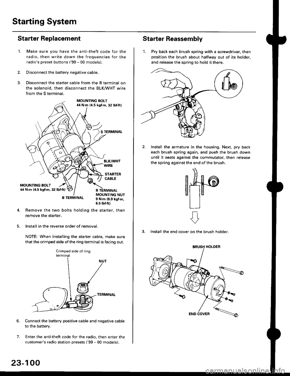
Starting System
Starter Replacement
1.Make sure you have the anti-theft code for the
radio, then write down the frequencies for the
radio's preset buttons ('99 - 00 models).
Disconnect the battery negative cable.
Disconnect the starter cable from the B terminal on
the solenoid, then disconnect the BLK trHT wire
from the S terminal.
MOUNTING BOLT44 N.m l/t.s kgf.m. 32 lbf.ft)
S TERMINAL
MOUNTING BOLT6,1 N.m {4.5 kstm.32lbtftl
MOUNTING NUT9 N,m {0.9 kgl.m,6.s lbtftl
B TERMINAL
4. Remove the two bolts holding the starter, then
remove the starter.
lnstall in the reverse order of removal.
NOTE: When installing the staner cable, make sure
that the crimped side ofthe ring terminal is facing out.
TERMINAL
Connect the battery positive cable and negative cable
to the battery.
Enter the anti-theft code for the radio, then enter the
customer's radio station presets ('99 - 00 models).
7.
Crimped side of ring
23-100
Starter Reassembly
'1. Pry back each brush spring with a screwdriver, then
position the brush about halfway out of its holder.
and release the spring to hold it there.
Install the armature in the housing. Next, pry back
each brush spring again, and push the brush down
until it seats against the commutator, then release
the spring against the end of the brush.
aw
3. Install the end cover on the brush holder.
ERUSH HOLDER
Page:
< prev 1-8 9-16 17-24