Page 190 of 2189

t
Valve Guides
Replacement
1. As illustrated below, use a commerciallv available
air-impact valve guide driver attachment modified
to fit the diameter of the valve guides. ln most
cases, the same procedure can be done using the
sDecial tool and a conventional hammer.
COMMERCIALLY AVAILABLEVALVE GUIDE DRIVER
87 mm -L- sz mm(3.43 inl I tz.zr int
rE-tt
10.8 mm10.42 inl
olVALVE GUIOE DRIVER,5.5 mm077,P - 0010100
Select the proper replacement guides and chill
them in the freezer section of a refrigerator for
about an hour.
Use a hot plate or oven to evenly heat the cylinder
head to 300"F (150"C). Monitor the temperature with
a cooking thermometer.
CAUTION:
. Do not use a torch; it may warp tho head.. Do not get tho head hotter than 300"F {150"C};excesgive heat may loosen thg valve seats.. To avoid burns. use haaw gloves whon handling
the heatod cylinder head.
6-80
Working from the camshaft side, use the driver and
an air hammer to drive the guide about 2 mm (0.1 in)
towards the combustion chamber. This will knock off
some ofthe carbon and make removaleasier.
CAUTION:
. Always wsar safety goggles or a face shield whsn
driving valve guides.
. Hold the air hammer dir€ctly in line with the
valve guide to prevont damaging thg dtiver.
Turn the head over and drive the guide out toward
the camshaft side of the head.
VALVE GUIOE DRIVER,5.5 mm077{2 - 0010100
lf a valve guide still won't move. drill it out with a8.0 mm (5/16 in) bit, then try again.
CAUTION: Drill guides only in extreme cases; you
could damago the cylinder head if ths guide br6aks.
Remove the new guide(s) from the freezer, one at a
time, as vou need them.
-:^-,65i^q
NNSp-<
Page 192 of 2189

Valves
1.
Installation
Coat the valve stems with oil. lnsert the valves into
the valve guides.
NOTE: Check that the valves move up and downsmoothly.
Installthe spring seats on the cylinder head.
Install the valve seals using the special tool.
NOTE: Exhaust and intake valve seals are not inter-
changeable.
WHITESPRING
VALVE GUIDE SEAL INSTALLERKD-28)g (Commercially available)NOTE: Use small lDend of tool,
2.
BRACKSPRING
VALVE SEALReplace.
tNsTALLERVALVE GUIDE SEALKD-2899NOTE: Use small lDend of tool
(
4. lnstall the valve spring and valve retainer, theninstall the valve spring compressor. Compress thespring, and install the valve keepers.
NOTE: Place the end of the valve spring with closely
wound coils toward the cylinder head.
VALVE SpRtNG VALVE SPRTNG
COMpRESSOR COMPRESSORATTACHMENT
ATTACHMENT EXTENSTON
0775? _ pJlOl0A o?MAF - PR9010A
VALVE SPRING COMPRESSORlCommercially available)Snap-on CF711 or KD-3tXlwith #32JAWSLightly tap the end of each valve stem two or threetimes with the wooden handle of a hammer to ensureproper seating of the valve and valve keepers.
NOTE: Tap the valve stem only along its axis soyou do not bend the stem.
I
5.
Page 234 of 2189
Oil Filter
Replacement
After the engine has been run, the exhaust pipe willbe hot; be careful when working around ihe exhaustpipe.
Be careful when loosening the drain bolt whils theengine is hot. Burns can resuh because the oil tem-peratu16 is very high.
Remove the oil filter with the oil filter wrencn.
Inspect the threads and rubber seal on the new filter.Wipe off the seat on the engine block, then apply alight coat of oil to the new filter,s rubber seal.
NOTE: Use onty fitters with a built-in bypass sys,tem.
Apply oil to rubber sealbefore installing.
l.
Inspect threads andrubber seal surface.
8-8
Install the oil filter by hand.
After the rubber seal seats, tighten the oil filter clock_wise with the oil filter wrench.
Tighten: 7/8 tu.n clockwise.
Tightening tolque: 22 N.m (2.2 kgt.m, 16lbf.ft)
OIL FILTER WRENCH07912 - 6110001
Page 1061 of 2189

Steering Gearbox
l.r
Rack Guide Adjustment
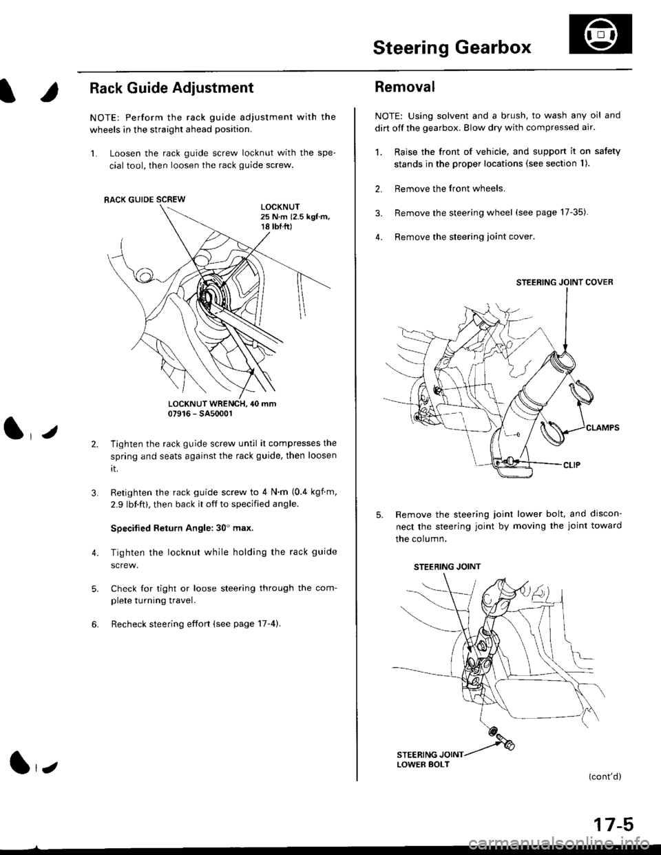
NOTE: Perform the rack guide adjustment with the
wheels in the straight ahead position.
1. Loosen the rack guide screw locknut with the spe-
cial tool, then loosen the rack guide screw.
LOCKNUT WRENCH, 40 mm07916 - SA5000r
Tighten the rack guide screw until it compresses the
spring and seats against the rack guide, then loosen
rt.
Retighten the rack guide screw to 4 N'm (0.4 kgf m,
2.9 lbf.ft), then back it off to specified angle.
Specilied Return Angle: 30' max.
Tighten the locknut while holding the rack guide
Check for tight or loose steering through the com-
plete turning travel.
Recheck steering effort (see page 17-4).
4.
RACK GUIDE SCREW
l,z
Removal
NOTE: Using solvent and a brush, to wash any oil and
dirt off the gearbox. Blow dry with compressed air.
1. Raise the front of vehicle, and support it on satety
stands in the proper locations (see section I ).
2. Remove the front wheels.
3. Remove the steering wheel (see page 17-35).
4. Remove the steering loint cover
Remove the steering joint lower bolt, and discon-
nect the steering joint by moving the joint toward
the column.
(cont'd)
17-5
STEERING JOINT COVER
LOWER BOLT
STEERING JOINT
Page 1066 of 2189

Steering Gearbox
Reassembly (cont'dl
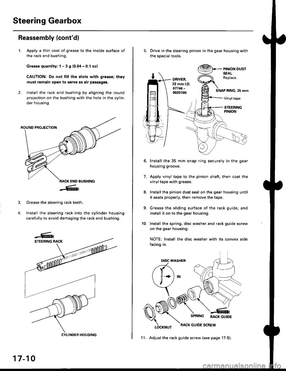
LApply a thin coat of grease to the inside surface of
the rack end bushing.
Grease quantity: 1 - 3 S 10.04-0.1 ozl
CAUTION: Do not till the slots with greas€; th€y
must remain open to serve as air passages,
Install the rack end bushing by aligning the round
projection on the bushing with the hole in the cylin-
der housing
4.
Grease the steering rack teeth.
Install the steering rack into the cylinder housing
carefully to avoid damaging the rack end bushing.
CYLINDER HOUSING
17-10
11. Adjust the rack guide screw (see page 17-5).
Drive in the steering pinion in the gear housing with
the soecial tools.
ORIVER.22 mm l.D.o7716-qr20100SNAP RING, 35 mm
PINION DUSTSEALReplace.
Vinyltape
STEERINGPINION
7.
Install the 35 mm snap ring securely in the gear
housing groove.
Apply vinyl tape to the pinion shaft, then coat the
vinyltape with grease.
Install the pinion dust seal on the gear housing until
it seats properly, then remove the tape.
Grease the sliding surface of the rack guide, and
install it on to the gear housing.
Install the spring, disc washer and rack guide screw
on the gear housing.
NOTE: Install the disc washer with its convex side
facing in.
LOCKNUT
SPRING RACK GUTDE
RACK GUIOE SCREW
10.
Dtsc w,
a(-\
l1 *l
\, ,/
\
Page 1231 of 2189
l}
e\
Body ('96 modell
Doors
Front Door Index (4D) ...20-2
Rear Door Index {4Dl .....20-8
Door fndex lzDl3Dl .......20-14
Emblems
f nstallation 20-118
Exterior
Component Location Index ............... 20-93
*Frame Repair Chart .......... 20-120
* Interior
Component Location Index ............... 20-58
Mirrors
Mirror Rep|acement .................. ......... 20-24
Mirror Holder/Gover Replacement ... 20-25
Rearview Mirror Reolacement .......... 20-25
Moonroof
lndex .......... .....................20-50
Opener Cable/Opener and Latch/
Wiper and Washer
Component Location Index .......... ...,. 20-107
Seats and Seat Belts
Gomponent Location Index .......... ..... 20-73
Sub-frame ....20-119
Windshield, Rear Window and Ouarter Glass
Index .......... .....................20-26
Body {'97 modell
Body ('98 modell
Body ('99 modell
Body ('00 model)
20-123
20-131
20-135
20-141
It
Page 1284 of 2189
Moonroof
Motor, Drain Tube and Frame Replacement
CAUTION:
. Put on gloves to protecl your hands.
. Be careful not to damage the seats, dashboard and other interior trim.
'1. Remove the headliner {see page 20-64).
2. Disconnect the motor connector and glass position switch connector.
NOTE: When removing the motor, detach the connector from the frame, remove the bolts and nuts, then remove the
motor.
3. Remove the glass {see page 20-52).
4. Disconnect the drain tubes, and detach the ceiling light harness.
5. Remove the frame mounting bolts.
NOTE;
. An assistant is helpful when removing the bolts.
. Remove the front bolts last.
6. Detach the rear hooks by moving the frame forward, then remove the frame.
BOLT6x1.0mm9.8 N.m {1.0 kgt m,7.2 tht.hl
6x1.0mm9.8 N m (1.0 kgl.m, 7.2 lbtft)
20-54
\
Page 1288 of 2189

Interior
Component Location Index
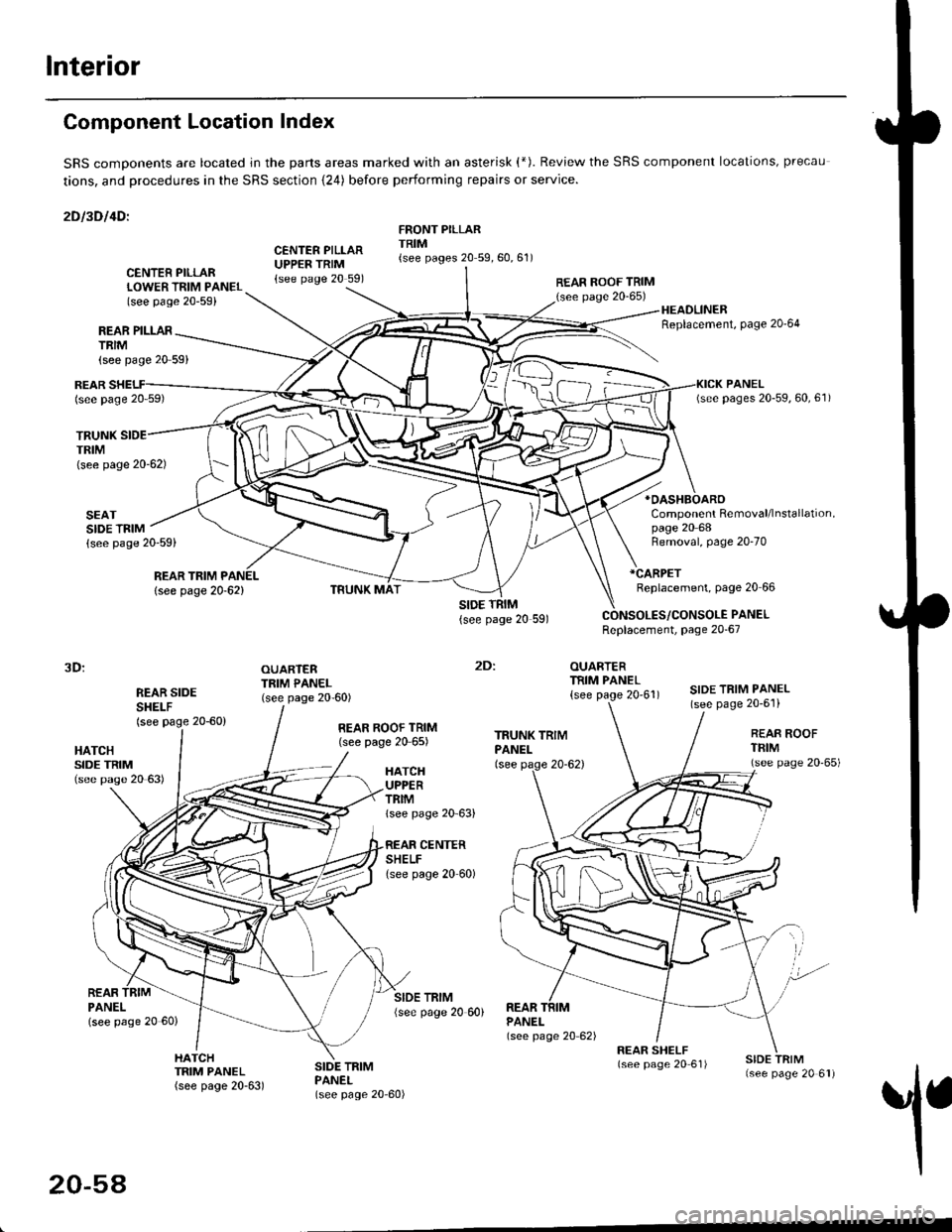
SRS comDonents are located jn the parts areas marked with an asterisk (*). Review the SRS component locations, precau
tions, and procedures in the SRS section {24) before performing repairs or service.
2Dl3Dl4Dl
CENTER PILLARUPPER TRIM{see page 20 591
FRONT PILLARTRIM{see pages 20 59,60,61)
REAR PILLARTRIM
TRUNKTRIM(see page 20-62)
SEATSIDE TRIM{see page 20-59)
{see page 20 59}
CENTER PILLARLOWER TRIM PANEL(see page 20-59)
REAR ROOF TRIM(see page 20-65)
:
OUARTERTRIM PANEL
{see page 20'61)
HEADLINERReplacement, Page 20'64
*OASHBOARO
Component Removal/lnstallation,page 20 68
REARlsee page 20 59)
REAR TRIM PANEL
lsee page 20-62)
Removal, page 20-70
*CARPET
Replacement, page 20 66
PANELReplacement, page 20-67
3D:
REAR SIDESHEI-F(see page 20-60)
OUARTERTRIM PANEL(see page 20-60)SIDE TRIM PANEL(see page 20-6'l)
2Dl
HATCHSIDE TRIM(see pase 20 63)
REAR ROOF TRIM(see page 20 65)REAR ROOFTFIM(see page 20'65)HATCHUPPERTRIMlsee page 20 63)
CENTERSHELFlsee page 20 60)
REARPANELlsee page 20 60)
SIDE TRIM{see page 20 60)REARPANEL(see page 20 62)
1
HATCHTRIM PANEL(see page 20-63)
SIDE TRIMPANEL(see page 20-60)
20-54