1996 HONDA CIVIC Ignition wires
[x] Cancel search: Ignition wiresPage 442 of 2189

(From page | 1-172)
Check fo. a sho.t in the CKP/
TDC/CYP sensor:Check for continuity to bodYground on both terminals of the
indicated senso r individually
1*see table).
Replaco the di3tributor ignition
hoGing lsee section 23).ls there continuity?
Check for an open in the wires
ICKP/TOC/CYP line3):1. Reconnect the distributor 10P
connecaor.2. Disconnect the EcM/PCM con-
nector C {31P}.3. N4easure resistance betweenthe terminals of the indicated
sensor on the ECIM/PCM con-
nector {*see tabie}.
Repair open in the indicated sen-
sor wires lrsee tablel.ls there 350 - 700 o?
Chock lor. short in the wires
ICKP/TDC/CYP lines):
Check for continuity between
body ground and ECM/PCM con-
nector terminals C2, C3 and/or C4individually.
Repai. short in the indic.ted sen_
sor wire3 ('soe tablol,ls there continuity?
Substitute e known-good ECM/PCM, and iecheck. ll sYmptom/indication goes awev, r€Place the
original ECM/PCM.
DISTRIBUTOR10P CoNNECTOR {C1201
Terminalside ofmale terminals
ECM/PCM CONNECTORS C 131P)
CI(P P TDC P CYP P(YEL)
M
CKP M(WHT)MIBLKI
Wire side offemale terminals
CYP PIYELI
(REDI
TDC P(GRN)CKP P(BLU}
t
TDC P (GRNI
11-173
Page 443 of 2189

PGM-FI System
l-Fos3sl
tFos36l
tF1361 l
Fr362-1
tF13sil
Crankshaft Position/Top Dead Center/Cylinder Position (CKP/TDC/CYPI Sensor
f99 - 00 Models except D16Y5 engine with M/T)
The scan tool indicates Diagnostic Trouble Code (DTC) P0335: A malfunction in the Crankshaft Position (CKP)
sensor circuit.
The scan tool indicates Diagnostic Trouble Code (DTC) P0336: A range/performance problem in the Crankshaft
Position (CKP) sensor circuit.
The scan tool indicates Diagnostic Trouble Code (DTC) P1361: Intermittent interruption in the Top Dead Center
{TDC) sensor circuit.
The scan tool indicates Diagnostic Trouble Code {DTC) P1362: No signal in the Top Dead Center (TDC) sensor
circuit.
The scan tool indicates Diagnostic Trouble Code (DTC) P1381: Intermittent interruption in the Cylinder Position(CYP) sensor circuit.
lTiaSt The scan tool indicates Diagnostic Trouble Code (DTC) P1382; No signal in the Cylinder Position (CYP) sensor: circuil.
DoscriDtion
The CKP Sensor determines timing for fuel injection and ignition of each cylinder and also detects engine speed. The TDC
Sensor determines ignition timing at start-up (cranking) and when crank angle is abnormal. The CYP Sensor detects the
position of No. 1 cylinder for sequential fuel injection to each cylinder. The CKP/TDC/CYP Sensor is built into the distribu-
tor.
NOTE; lf DTC P1359 is stored at the same time as DTC P0335, P0336, P1361. P1362, P1381 and/or P1382, troubleshoot DTC
P1359 first, then recheck for those DTCS. D16Y5 engino:
SENSORROTOR
TDGSENSORCKPSENSOBTDCSENSOBCKPSENSOBCYPs€NsonBOTORROTORBOTONROTOR ROTOR
D16Y7, D16Y8 ongine:
(To page 11-175)
1-174
- The MIL has been reportod on.- DTC P0335, P0336. P1361,P1362, P1381 rnd/or P1382.restored.
Problem verific{tion:1. Do the ECM/PCM Reset Proce-dure.2. Start the engine.
Intormittcnt failure, systom b OKat thb time. Check to. poor con-nections or loose wires at C120(dktributorl and ECM/PCM.
ls DTC P0335, P0336, P1361, P1362,P1381 and/or Pl382 indicated?
Check tor an open in the CKP/TDC/CYP 3enior:1. Turn the ignition switch OFF.2. Disconnect the distributor 10Pconnector,3. Measure resistance betweenthe terminals of the indicatedsensor (*see table).
Replrce the distributor ignitionhou3ing (!ee section 231.ls there 350 700 0?
SENSORDTCSENSORTEBMINAIECM/PCMTERI\,4INAICOLOR
CKPP0335
P0336
2c88LU
6c9
TDCP1361
P1362
3c20GRN
7c21BED
CYPP1381
P1342
c29YEL
Ic30BLK
Page 445 of 2189

PGM-FI System
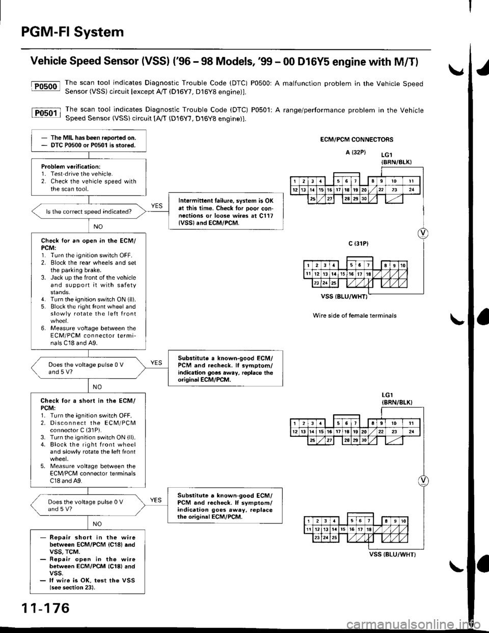
Vehicle Speed Sensor (VSSI ('96 - 98 Models,'99 - 00 D16Y5 engine with M/Tl
@The scan tool indicates Diagnostic Trouble Code (DTC) P0500: A malfunction problem in the Vehicle SpeedSensor (VSS) circuit Iexcept A!/T (D16Y7, D16Y8 engine)1.
The scan tool indicates Diagnostic Trouble Code (DTC) P0501: A range/performance problem in the VehicleSpeed Sensor (VSS) circuit [A,rT {D16Y7, D16Y8 engine)].
ECM/PCM CONNECTORS
A {32P} LG.t
VSS IBLU/WHT}
Wire side ot temale terminals
LGI(BRN/8LK}
The MIL has been reDorted on.DTC P0500 or P0501 is stored.
Problem verification:1- Test drive the vehicle.2. Check the vehicle speed withthe scan tool.
Intermittent tailure, system is OKat this time. Check tor Door con-nections or loose wires at C117{VSSland ECM/PCM.
ls the correct speed indicated?
Check for an open in the ECM/PCM:1. Turn the ignition switch OFF.2. Elock the rear wheels and setthe parking brake.3. Jack up the front of the vehicleand support it with safetystands.4. Turn the ignition switch ON (ll).
5. Block the right tront wheel andslowly rotate the left front
6, Measure voltage between theECM/PCM connector termi-nals C18 and A9.
Subslitute a known-good ECM/PCM and recheck. lf symptom/indic.tion goes away, replace theorisinal ECM/PCM.
Does the voltage pulse 0 Vand 5 V?
Check tor a short in ihe ECM/PCM:1. Turn the ignition switch OFF.2. Disco n n ect the ECM/PCMconnector C (31P).
3. Turn the ignition switch ON {ll).4. Block the right front wheeland slowly rotate the left front
5. Measure voltage between theECM/PCM connector terminalsC18 and A9.
Substitute a known-good ECM/PCM and recheck. lI symptom/indication goes away. replacethe original ECM/PCM.
Does the voltage pulse 0 Vand s V?
- Repair short in the wirebetwGen ECM/PCM {C18} endvss, TcM.- Repair open in the wirebetween ECM/PCM {Cl8} andvss.- lf wire is OK, test the VSSlsee section 23).
{BRN/BLK}
239l0lt
121611t8t9202321
2A2930
c {31P}
I38191o
tl12ialr5i6l10./
I2356a9l011
12l3l5t61tl8t920222a
27202930
12910
t2l13l.l7I l,/ 1,/231r.lslt., ),rlL
VSS {BLU/WHT}
11-176
Page 448 of 2189

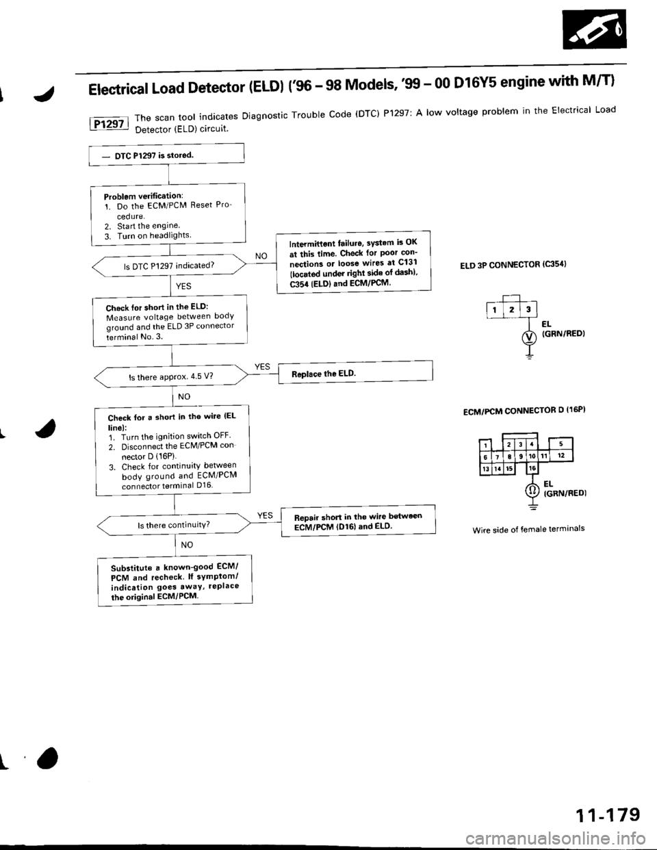
Electrical Load Detector (ELDI {'96 - 98 Models,'tn - 00 D16Y5 engine with M/T}
The scan tool indicates Diagnostic Trouble code (DTC) P1297: A low voltage problem in the Electrical Load
Detector (ELD) circuit.
ELD 3P CONNECTOR (c35'rl
l-- ,ll l2l3l--f ..
ao (GRN/REDI
Y
ECM/PCM CONNECTOR O I16PI
Wire side of female terminals
Problem verification:'!. Do the ECM/PCM Reset Pro-
cedure.2. Sta rt the engine
3. Turn on headlightslntermittent tailure, sYstem is OK
at this time. Check for Poor con-
nection3 or loose wires at C131
tlocated under righl side of da3h).
C354 (ELDIand ECM/PCM.
ls DTC P1297 indicated?
Ch.ck lor short in the ELD:
Measure voltage between body
ground and the ELD 3P connector
terminal No.3.
ls there approx.4 5 V?
Check for a short in tho wile (EL
linel:1. Turn the ignition switch OFF'
2. Disconnect the ECM/PCM con
nector D (16P)
3. Check for continuity between
body ground and ECM/PCM
connector terminal D16
R6pair short in the wire between
ECM/PCM (D161and ELD.
Substitute a known-good ECM/
PCM and recheck lf symplom/
indication goes awaY, rePlace
the original ECM/PCM
ra
11-179
Page 449 of 2189

PGM-Fl System
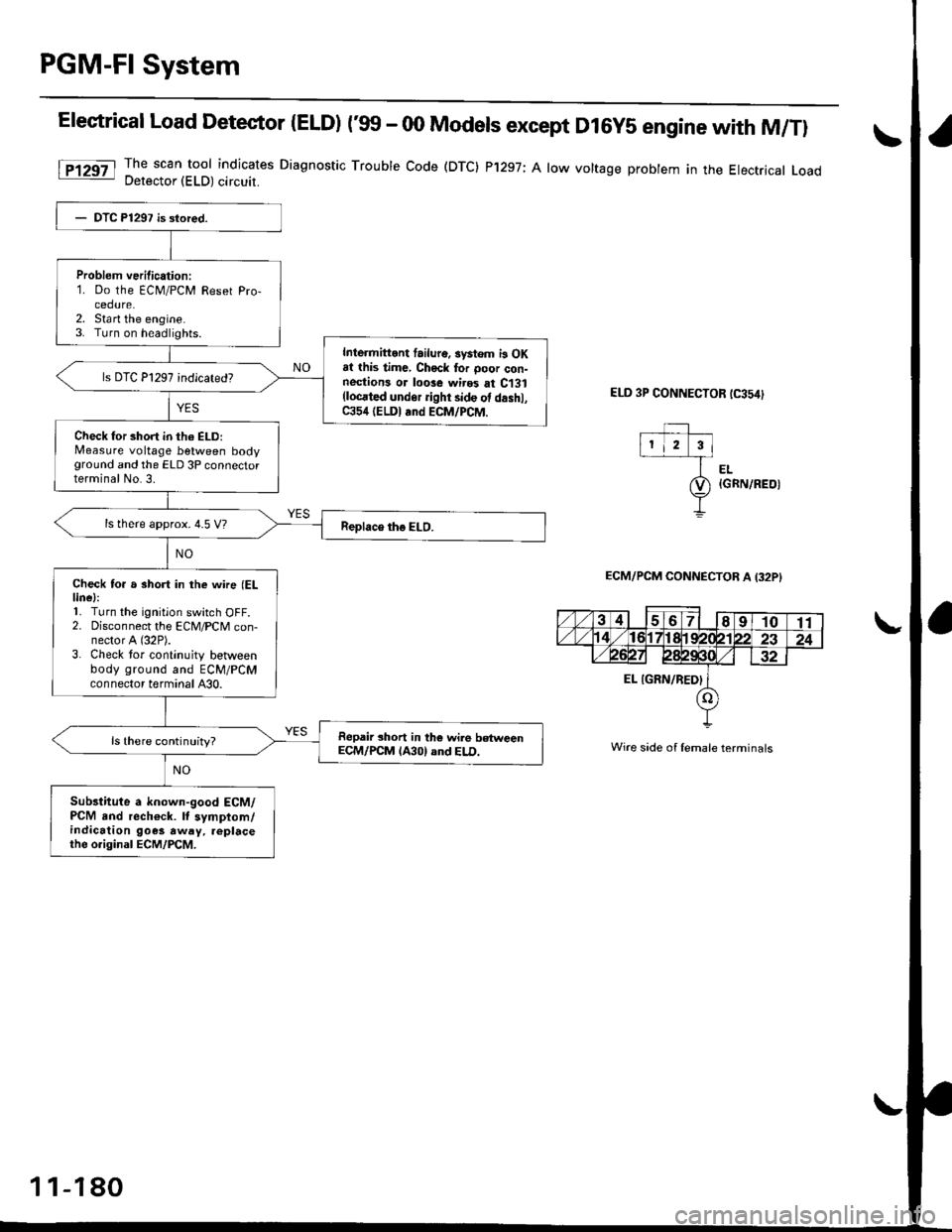
Elestrical Load Detector |ELD) t'glf - 00 Models except D16y5 engine with M/Tl
The scan tool indicates Diagnostic Trouble Code (DTC) P'1297; A low voltage probtem in the Electrical LoadDetector (ELD) circuit.
ELD 3P CONNECTOR tC354)
EL{GRN/REOI
ECM/PCM CONNECTOB A I32PI
Wire side of lemale terminals
Problem verilication:1. Do the ECM/PCM Reset Pro-cedure.2. Sta rt the engine.3. Turn on headlights.
Inlermittont failur6. systom i3 OKat this time, Chock tor ooor con-nestions or loose wires at C131(locrted undor ight side ot d.shl,C354 (ELDI and ECM/PCM.
Check for short in th6 ELD:Measure voltage between bodyground and the ELD 3P connectorterminal No.3.
ls there approx. 4.5 V?
Check to. a short in the wne (ELlinel:'L Turn the ignition switch OFF.2. Disconnect the ECM/PCM con-nector A (32P).
3. Check tor continuity betlveenbody ground and ECM/PCMconnector terminal A30.
Repair short in the wile betweenECM/PCM lA30) and ELD.ls there continuity?
Sub3titute a known-good ECM/PCM and rech€ck. It symptom/indication goes away. replacethe o.iginal ECM/PCM.
1 1-180
Page 451 of 2189

PGM-FI System
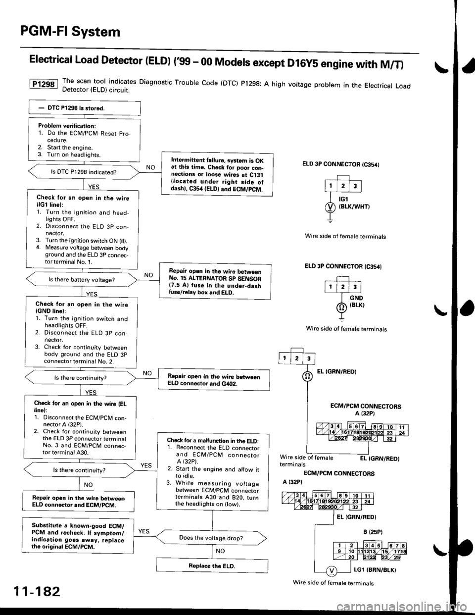
Elestrical Load Detector (ELDI ('99 - 00 Models except D16y5 engine with M/Tl
The scan tool indicates Diagnostic Trouble code (DTCI Pl298: A high vottage problem in the Etectrical LoadDetector (ELD) circuit.
ELD 3P CONNECTOR (65/0
EL {GRN/REOI
Wire side of fernale terminals
ELD 3P CONNECTOR (CA54I
TIr l2l3l
I crvo
(o) (BrKr
Y
Wire side of lemale terminals
ECM/PCM CONNECTORSA (32P1
Wire side of lemaleEI- IGRN/RED)terminals
ECM/PCM CONNECTORS
A {32P)
Problem ve.itication:1. Do the ECN4/PCM Reset pro
cedure.2. Start the engine.3- Turn on headiights.Inte.mittent teilu.e, svstem is OKat this lime. Chock for Door con-nections or loose wires at Ci31{located under Jight side otdaihl, C354 (ELD) and ECM/PCM.
ls DTC P1298 indicated?
Check for an open in the wire{lG1 line}:1. Turn the ignition and head-lights OFF.2. Disconnect the ELD 3P con
3. Turn the ignition switch ON (ll).4. Measure voltage between bodyground and the ELD 3P connec-torterminalNo. 1.
Repair opon in tho wiro batwe€nNo. 15 ALTERNATOR Sp SENSOR{7.5 A} fuse in th6 undor-dashIuse/reley box and ELD.
ls there battery voltage?
Check for an open in the wiro{GND linel:1. Turn the ignition switch andheadlights OFF.2. Disconnect the ELD 3P connector.3. Check for continuity betweenbody ground and the ELD 3Pconnector terminal No. 2,
Repair open in the wire bstwoenELD connsctor and Gia02.
Check ,or an open in the wire IELlinel:1. Disconnect the ECM/PCM con-nector A (32P).2. Check for continuity betweenthe ELD 3P connector terminalNo. 3 and ECM/PCM connec-tor terminal A30.
Chock fo. a malfunction in the ELD:'1. Reconnect the ELD connectorand ECM/PCM connectorA (32P).
2. Stan the engine and allow itto idle.3. While measuring voltagebetween ECM/PCM connectorterminals A30 and B2O, turnthe headlighrs on ow).
ls there continuity?
Repsir op€n in the wire betweenELD connector and ECM/PCM.
Substitute a known-good ECM/PCM and recheck. lf symptom/indication goes away. replacelh6 original ECM/PCM.
Does the vokage drop?
Wire side of f€male terminals
11-182
Page 458 of 2189

[F16551l Th" ""un toot indicates Diagnostic Trouble Code (DTC) P1681: TIVA,/TMB signal line failure
Problem verification:1. Do the ECM Reset Procedure.
2. Drive the vehicle Ior several
miles at varying speeds
lnt.rmittent failure, system is OK
at ihis time. Check tor Poor con-
nections or loos€ wires at C131
llocated under right side of dash),
C438 ITCM) and ECM.
ls DTC P1655 indicated?
Check lor an oPen in the wire(TMA line):1. Turn the ignition switch OFF
2. Disconnect ECM connector C(31P)from the ECM
3. Turn the ignition switch ON (ll).
4- Measure vo ltag e between
ECM connector terminal Cg
and body ground.
Check for a short in the wire
ITMA line,:Measure voltage between TCM
22P connector terminal No 7 and
body ground.ls there battery vohage?
Ropair shod in the wire bstwe€n
the EcM (C!l) and the TcM.ls there battery voltage?
Check for an open in the wire
{TMB line}:1. Turn the ignition switch OFF
2. Reconnect ECM connector c(31P).
3. Disconnect the 22P connector
from TCM.4. Turn the ignition switch ON (ll).
5. Measure vo ltage between
TCM 22P connector termlnal
No. 6 and body ground.
Repair open in the wire between
th€ EcM {Ca) and the TcM.
Check for a 3ho.t in the wire
{TMB lin6,:Measure voltage between ECM
connector terminal C30 and bodyground,
ls there battery voltage?
Substitute a known'good ECM
and recheck. It symPtom/indica'tion goes away, teplace the origi-
nal ECM.
Reoair short in the wile b6tween
the ECM {C30} and the TCM.ls there baftery voltage?
f,epair open in the wire between
the EcM (C30) and the TcM.
IJA/T Signal (TMA/TMBI ('96 - 98 Dl6Y5 engine with GW)
ECM CONNECTOR C 131P}TMA IGRYI
fcu22PCONNECTOR
ll
TMB*{PNK}
231678910
1t'12131415161718
232a252930
Wire side oI temale
terminals
tl,
1 1-189
Page 465 of 2189
![HONDA CIVIC 1996 6.G Workshop Manual ldle Gontrol System
ldle Air Control (lAG) Valve (99 - 00 Dl6Y8 engine with M/T, Bt6A2 enginel
[Fl50g l ]h" scan tool indicates Diagnostic Trouble Code (DTC) P1508: A problem in the ldle Air Controt HONDA CIVIC 1996 6.G Workshop Manual ldle Gontrol System
ldle Air Control (lAG) Valve (99 - 00 Dl6Y8 engine with M/T, Bt6A2 enginel
[Fl50g l ]h" scan tool indicates Diagnostic Trouble Code (DTC) P1508: A problem in the ldle Air Controt](/manual-img/13/6068/w960_6068-464.png)
ldle Gontrol System
ldle Air Control (lAG) Valve ('99 - 00 Dl6Y8 engine with M/T, Bt6A2 enginel
[Fl50g l ]h" scan tool indicates Diagnostic Trouble Code (DTC) P1508: A problem in the ldle Air Controt AC) vatve- CtrCUtt.
The IAC Valve changes the amount of air bypassing the throttle body in response to a current signal from the ECM inorder to maintain the proper idle speed.
IAC VALVE 2P CONNECTOR IC138'
la rcprI - {YEL/8LKI 2t--d,
Y-=
Wire side ot female terminals
Wire side of lemale terminals
VALVE
The MIL has boon r€oorted on.DTC P1508 is srored.
Probl6m verification:1. Do the ECM/PCM Reset Pro-cedure.2. Start the engine, and warm itup to normal operating lem-perature.
Intermittent tailure, system is OKat this timg. Check to. poor con-noctions or loose wires at C138{lAC valvel and ECM.
ls DTC P1508 indicated?
Ch6ck for an open in the wir€{lGPl lino}:1. Turn the ignition switch OFF.2. Disconnect the IAC valve 2Pconnector.3. Turn the ignition switch ON (ll).
4. Measure voltage between bodyground and the IAC valve 2Pconneclor termina I No.2,
Repair opon in the wire bgtwoenIAC valve and PGM-Fl main relay.
Check tof an open or short in thewire {IACV line}l1. Turn the ignition switch OFFand reconnect the IAC valve
2. Disconnect the ECM connectorB {25P).3. Turn the ignition switch ON (ll).
4. Measure voltage betweenbody ground and ECM conn€ctor terminal 823.
(To page 11-197)
1 1-1 96