Page 939 of 2189

Electrical Troubleshooting ('96 - 98 Modelsl
Troubleshooting Flowchart - Pl Indicator Light Does Not Gome On
TCM CONNECTOR A {26P)
BLI
l-I
123a589101t12nl
1a151617202325rt
o
8LK
Wire side of female terminals
The E Indicator light does notcome on when the ignition switchis tirst turned ON {ll). {lt shouldcome on for aboul two s€conds,)
Chock the Service Check Connec-lot:Make sure the special tool (SCS
Service Connector) is not connected to the seryice check connector,
ls the special tool (SCS ServiceConnector) connected to the ser-vice check connector?
Disconn€ct the sDecial tool fromthe seruice check connector andrecheck.
Check the E Indicator Light:Shift to [5] oosition.
Check fo. loose TCM connectors.lf neceasary, substitute a known-good TCM .nd rochock.
Does the E indicator lightcome on?
Ch€ck th6 Ground Circuit:1. Turn the ignition switch OFF.2. Disconnect the A 126P) con-nector from the TCM.3. Check tor continuity betweenthe A13 terminal and bodyground and the 426 terminaland body ground.
.Repair open in the wiresbetwoon lhe A13 or A26 termi-nel3 and G101.. Repai. poor ground {G1011.
To page 14-263
14-262
>.
Page 948 of 2189

JTroubleshooting Flowchart - Shift Control Linear Solenoid
NOTE: Record all freeze data before you troubleshoot
Possiblc Cause
. Disconn€cted solenoid harnos3
connectol. Short or oDen in shilt controllinetr solonoid wiro. Faulty shift control linear sole_
noid. Op€n in VB SOL wite. ODen in PG'l and PG2 wires or
poor ground {G10'l)
f,
wire side ot female terminals
LG1 IBRN/BLKILG2IBRN/BLK)
{cont'd)
14-271
PCM CONNECTORS
B(25P) - Dll6P)
.OBD ll Scan Tool indicatos
Code P1870.. Solf-diagnosis E indic.lor light
indic.t€s Code 30.
M6a3ure VB SOL voltage:1. Turn the ignition switch OFF.
2. Disconnect the B 125P) and D(16P) connectors from the
PCM,3. Turn the ignition switch ON (ll).
4. Measure the voltage between
the D5 and 820 or 822 terminals.
Repair open or shod in the wire
between the D5 terminal and the
under-dash tuso/telay box.
Check the Ground Circuitl1. Turn the ignition switch OFF.2. Check lor continuity between
the terminafs 82 and 822 and
between terminals 810 and
820.
Repair open in the wi.e betwoen
the termin.ls 82, B10, B20, and
822 and G101. Repair Poolground (G101).
LG1 IBRN/BLKI
PCM CONNECTOR B PsPI
PG,I IBLK)
10 page 14-272
a
Page 950 of 2189
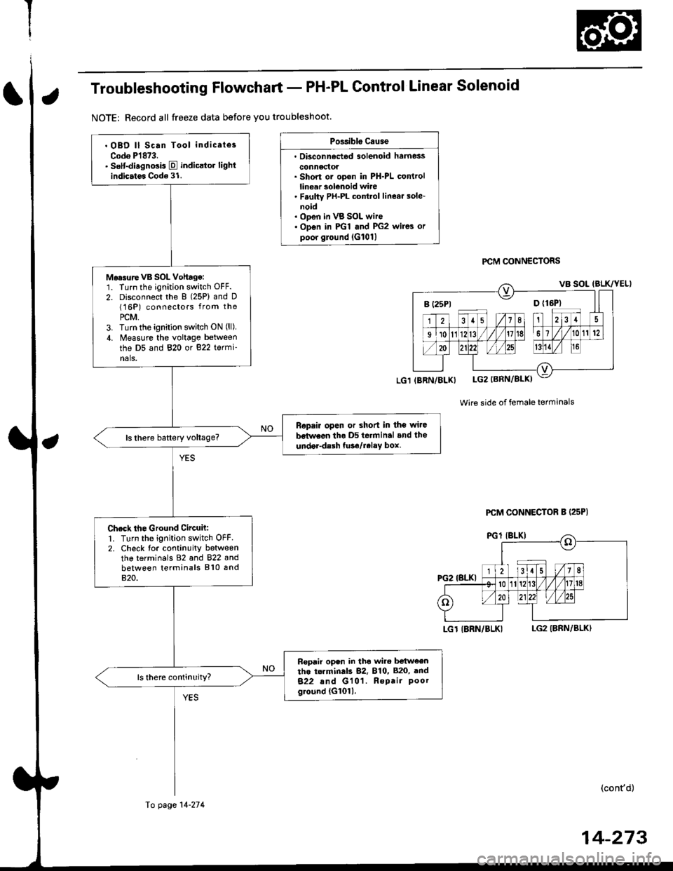
Troubleshooting Flowchart - PH-PL Control Linear Solenoid
NOTE: Record all freeze data before you troubleshoot.
Possibls c.use
. Oisconn6dod solenoid harness
conn6ctol. Short or ooen in PH-PL controllinear solenoid wire. F.ulty PH-PL cont.ol linear sole-noid. ODen in VB SOL wire. Op€n in PGl and PG2 wires orpoor ground lG101l
PCM CONNECTORS
Wire side of female terminals
LGT IBRN/BLKILG2 IBRN/BLK)
(cont'd)
B (25P1 D {16P}
. OBD ll Scan Tool indicates
Codo P1873.. sslt-disgnosis E indicltor lightindicates Code 31.
Mo.surevB SOL Vohagg:1. Turn the ignition switch OFF.
2. Disconnect the 8 (25P) and D(16P) connectors from the
PCM,3. Turn tho ignition switch ON (ll),
4. Measure the voltage between
the D5 and 820 or 822 termi-nals,
Ropair open or shod in the wiJe
bstwaon tho D5 terminal and the
under-dalh tuso/relay box.
Check the Ground Circuh:1. Turn the ignition switch OFF2. Check tor continuity betweenthe terminals 82 and 822 andbetween terminals 810 and820.
Fepair open in tho wiro b€tw€entho torminds 82, 810, 820, and
822 and G101. Repair Poorground (G1011.
(BRN/BLX)
Fo page 14-274
PCM CONNECTOR B (25P|
14-273
Page 952 of 2189
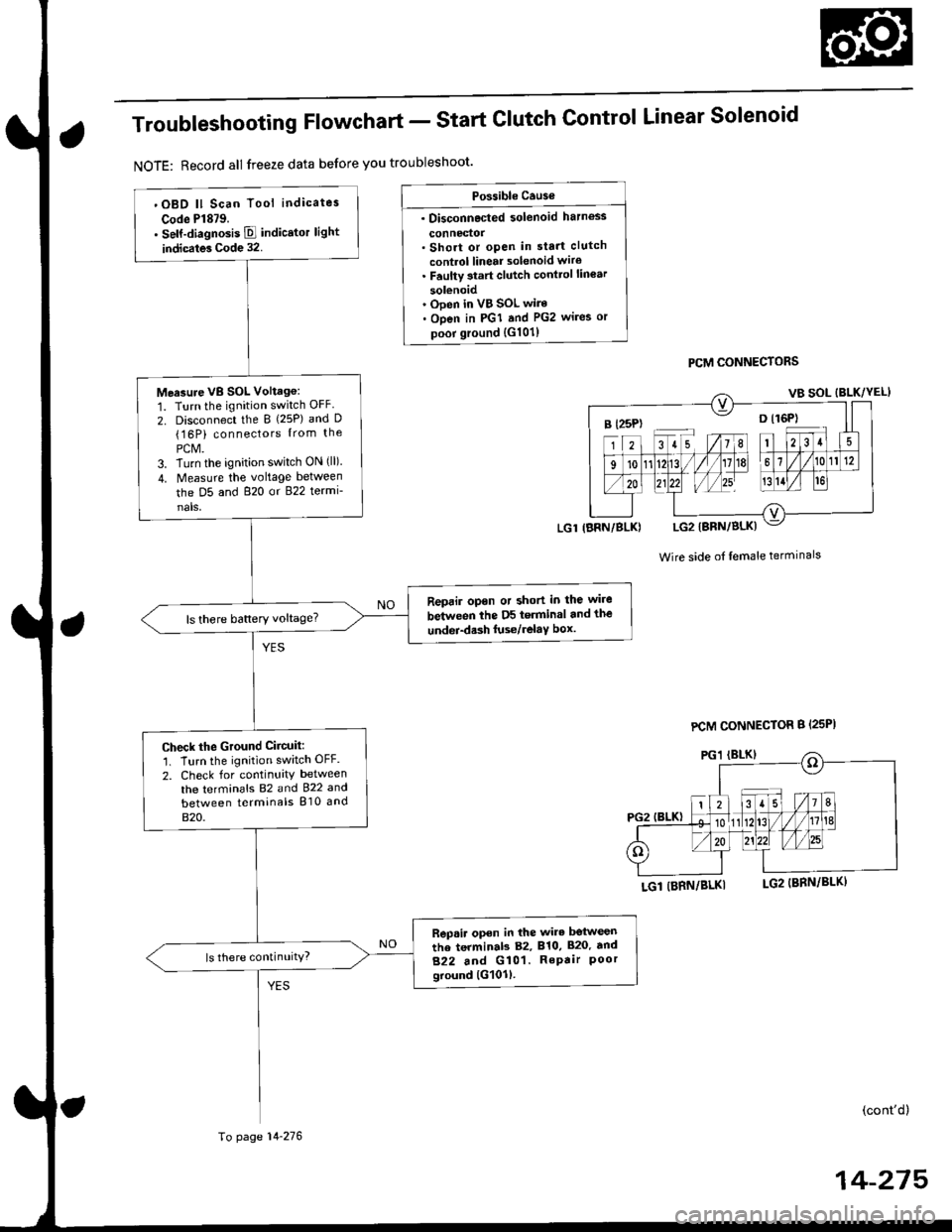
Troubleshooting Flowchart - Start
NOTE: Record all freeze data before you troubleshoot'
Clutch Control Linear Solenoid
PCM CONNECTORS
Wire side of lemale terminals
LGl (BRN/BLKI
(cont'd)
14-215
Po$ible Cause
. Disconnected solenoid harness
connedol. Short or open in sta.t clutch
control linear solenoid wiro. Faulty 3tart clutch conttol lin€ar
solenoid' Ooen in VB SOL wire. Open in PGI and PG2 wires or
poor ground {G101)
B l25P) -- o l16P)
'OBD ll Scan Tool indicates
Code Pl879.. self-diagnosis E indicstor light
indicates Code 32.
Measure VB SOL Voltag6:
1. Turn the ignition switch OFF
2. Disconnect the B {25P) and D(16P) connectors {rom the
PCM.3. Turn the ignition switch ON (ll).
4. Measure the voltage between
the D5 and 820 or 822 termi-
nals,
Reprir opon or short in the wire
between the D5 terminal and the
undei-d.sh luse/relaY box.ls there battery voltage?
Check the Ground Ciicuit:'1. Turn the ignition switch OFF.
2. Check for continuity between
the terminafs 82 and 922 and
between terminals 810 and
820.
Rep.ir open in the wire betwesn
the terminab 82, 810, 820. tnd
822 and G101. RePair Poorground lG101l.
ls there continuity?
LGl IBRN/BLK)
To page 14-276
PCM CONNECTOR B {25PI
Page 954 of 2189
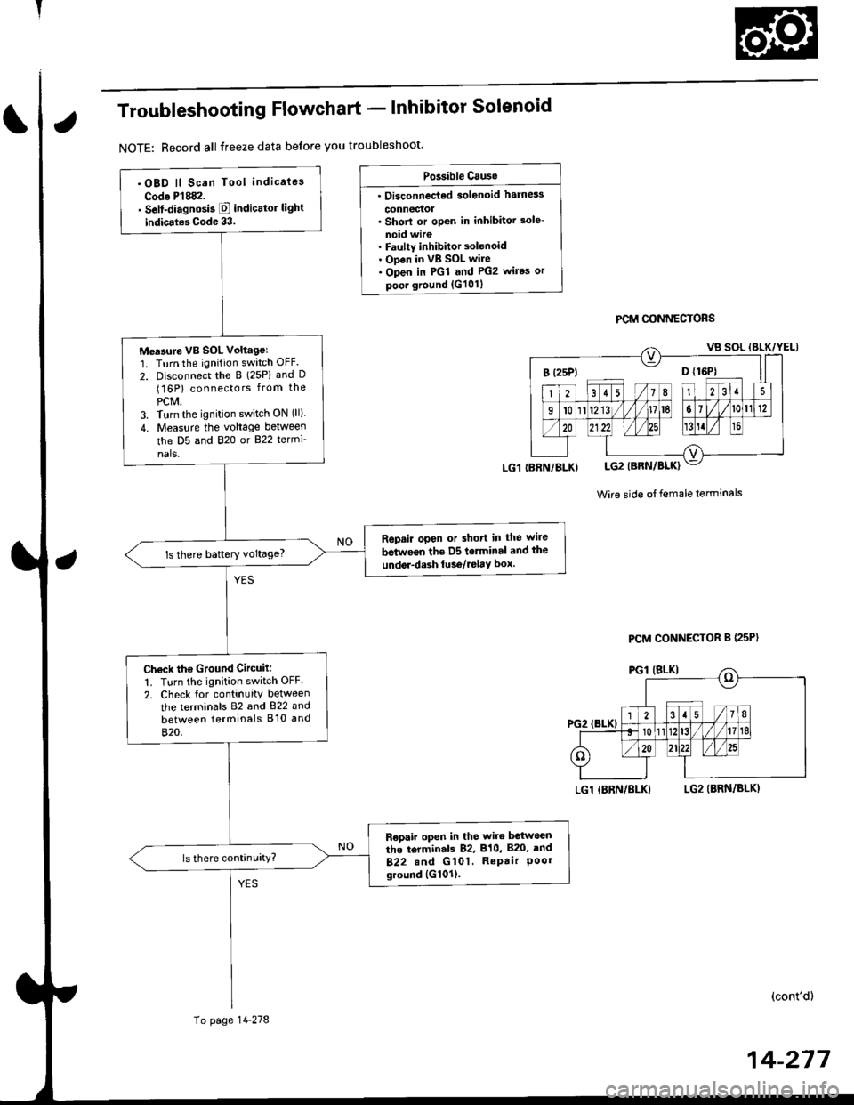
Troubleshooting Flowchart - lnhibitor Solenoid
NOTE: Record all freeze data before you troubleshoot'
Po3sible Cause
. Oi3connec'ted solenoid harn6s
connectoa. Shorl or open in inhibitor 3ole-
noid wir€. Faulty inhibitor solenoid. ODen in vB SOL wire. Open in PGl and PG2 wires or
poor ground {G101}
PCM CONNECTORS
Wire side ot female terminals
LGl IBRN/BLKILG2 (BRN/BLKI
(cont'd)
14-217
.OBD ll Scan Tool indicaies
Codo P'l882.. Self-diagnosis E indicttor light
indic.tes Code 33.
Me'sure VB SOL voltagel'1. Turn the ignition switch OFF.
2. Disconnect the B (25P) and D(16P) connectors from the
PCM.3. Turn the ignition switch ON (ll)
4. Measu.e the voltage between
the D5 and 820 or B22 termi-
nals.
Repair open or short in the wire
between the D5 tolminal and the
undor-dash lu36/relay box.ls there baftery voltage?
Ch€ck the Ground Circuit:
1. Turn the ignition switch OFF.
2. Check tor continuity between
the terminals 82 and 822 and
between terminals B'10 and
820.
R€pair open in the wire between
the torminal3 82, 810, B20, and
B22.nd G 101. RePair Poorground {G101).
(BRN/BLKI
To page 14-278
PCM CONNECTOR B {25P}
Page 1093 of 2189
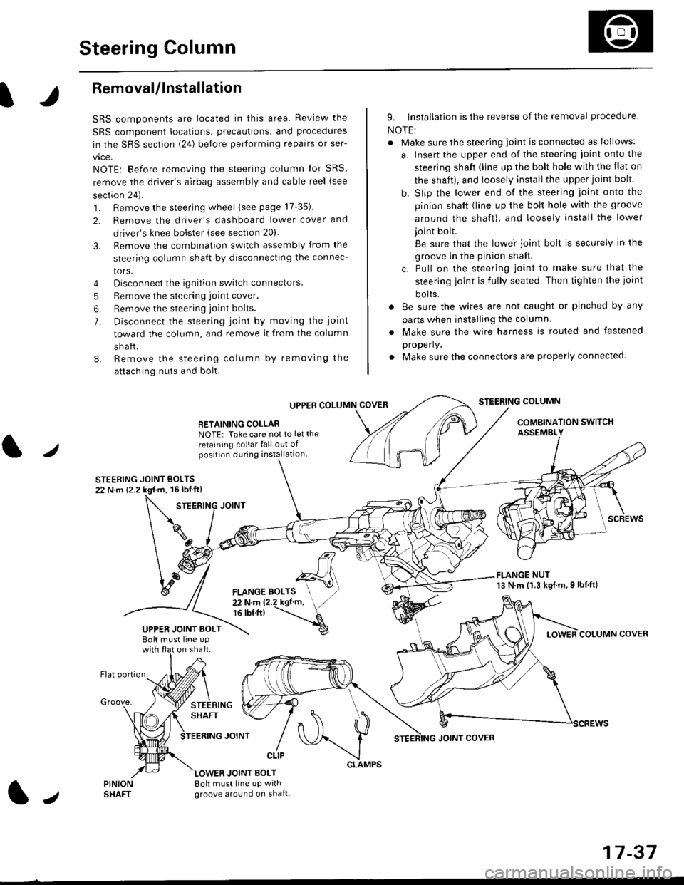
Steering Column
I
Removal/lnstallation
SRS components are located in this area. Review the
SRS component locations, precautions, and proceclures
in the SRS sectron (24) before pertorming repairs or ser-
vice.
NOTE: Before removing the steering column for SRS,
remove the driver's airbag assembly and cable reel lsee
section 24).
1. Remove the steering wheel (see page 17 35).
2. Remove the driver's dashboard lower cover and
driver's knee bolster (see section 20).
3. Remove the combination switch assembly from the
steering column sha{t by disconnecting the connec-
tors.
4. Disconnect the ignition switch connectors.
5. Remove the steering joint cover.
6. Bemove the steering joint bolls.
7. Disconnect the steering ioint by moving the joint
toward the column, and remove it from the column
shaft.
8. Remove the steering column by removing the
attaching nuts and bolt.
UPPER
RETAINING COLLABNOTE: Take care not to let the
retaining collar fall out ofposition during installation.
STEERING JOINT BOLTS22 N.m {2.2 kgf.m, 16lbtft}
9. Installation is the reverse of the removal procedure
NOTE:
. Make sure the steering joint is connected as follows:
a. Insert the upper end of the steering ioint onto the
steering shaft (line up the bolt hole with the flat on
the shait), and loosely install the upper joint bolt.
b. Slip the lower end of the steering joint onto the
pinion shaft (line up the bolt hole with the groove
around the shaft), and loosely install the lower
joint bolt.
Be sure that the lowei joint bolt is securely in the
groove in the pinion shaft.
c. Pull on the steering joint to make sure that the
steering joint js fully seated. Then tighten the ioint
bolts.
. 8e sure the wires are not caught or pinched by any
parts when installing the column
. Make sure the wire harness is routed and fastened
properly.
. Make sure the connectors are properly connected.
STEERING COLUMN
COMBINATION SWITCHASSEMBLY
FLANGE NUT13 N.m {1.3 kgl.m.9 lbf ft)
COLUMN COVER
FLANGE BOLTS22Nm12.2kgl'm,16 tbt.tr)
UPPER JOINT BOLTBolt musl line upon shaft.
Groove.
LOWER JOINT BOLT8oh must line up wrthgroove around on shaft.
CLIP
J
JOINT COVER
17-37
Page 1399 of 2189
![HONDA CIVIC 1996 6.G Workshop Manual Mode control motor does not run.
or one or more modes arc inope]a-
tive.
Check the No. 17 (7.5 A) fuse in
the under-dash fuse/relay box.
Replace the Iuse. and recheck.
Check for an open in the wire:
1 HONDA CIVIC 1996 6.G Workshop Manual Mode control motor does not run.
or one or more modes arc inope]a-
tive.
Check the No. 17 (7.5 A) fuse in
the under-dash fuse/relay box.
Replace the Iuse. and recheck.
Check for an open in the wire:
1](/manual-img/13/6068/w960_6068-1398.png)
Mode control motor does not run.
or one or more modes arc inope]a-
tive.
Check the No. 17 (7.5 A) fuse in
the under-dash fuse/relay box.
Replace the Iuse. and recheck.
Check for an open in the wire:
1. Disconnect the mode control
motor 7P connector,
2. Turn the ignition switch ON (ll)-
3. MeasLrre the voltage between
the No. 1 terminal of themode control motor 7P con
nector and body ground
Repair open in the wire between
the No. 17 luse and lhe mode
control motor.ls there battery voltage?
Check the mode control motor:
1- Turn the ignition switch OFF
2, Test the mode control motor(see page 21 47).Check lhe mode control linkage
and doors:1. Remove the mode controlmotor (see page 21 47).
2. Check the mode control linkage
and doors for smooth move
ls the mode control motor OK?
Do the mode control linkage
and doors move smoothlY?
ReDlace the mode control motor'
Check for a short to Power in the
wires:1. Iurn the,gnitjon switch ON(ll).
2, Disconnect the heater controlpanel20P connector.3. Check for voltage betweenthe No. 2, 5, 6, 7, I and 9 ter'minals of the heater controlpanel 20P connector andbody ground individuallY.Repair shorl to power in the
wire{sl between the heater con-
trol oanel and the mode controlmotor. This short also damagesthe heater control Pan6l. RePair
the short to power before replac'ing the heater control Panel
ls lhere any voltage?
MODE CONTROL MOTOR 7P CONNECTOR
t2315
BLK/YEL
Wire side of female terminals
HEATER CONIROL PANEL 2OP CONNECTOR
Wire side of female terminals
NO
(cont'd)
21-25Io page 21 26
Page 1400 of 2189
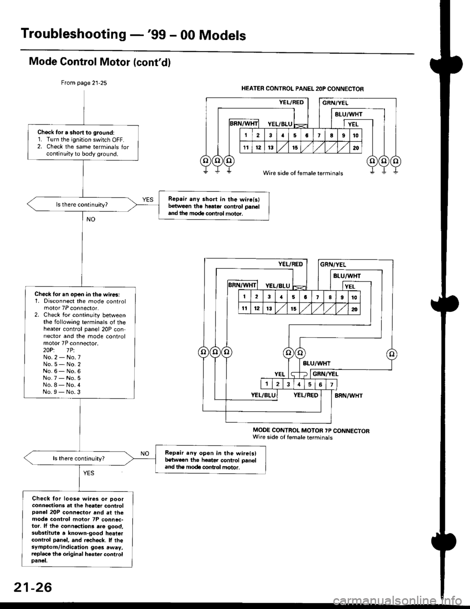
Troubleshooting -'gg - 00 Models
Mode Gontrol Motor (cont'dl
From page 21-25
MODE CONTROL MOTOR ?P CONNECTORWire sade of lemale terminals
Chock tor a short to ground:1. Turn the ignition switch OFF.2. Check the same terminals forcontinuity to body ground.
Repair any 3hort in the wirelslbetween the heater control paneland ihe mode control motor.
ls there continuity?
Check lor.n open in tho wires:1, Disconnect the mode controlmotor 7P connector.2. Check for continuity betweenthe following terminals of theheater control panel 20P connector and the mode controlmotor 7P connector.2OP: lPiNo.2 - No.7No.5- No.2No.6- No.6No.7 - No.5No.8- No.4No.I - No.3
Repair any opon in the wire(s)t€tween the h€ater control paneland tha modc contol motor.
ls there continuity?
Check for loose wiaes or ooorconnections at the heater controlpanel 20P connector rnd at themode control motor 7P connec-toa, lf the connoctions ere good,substitute a known-good heatercontrol panol, and recheck. lf thesyfiptom/indication goes away,replac€ the original hoater controlpanel.
HEATER CONTROL PANEL 2OP CONNECTOR
Wire side of female terminals
21-26