1996 HONDA CIVIC Gauge connector
[x] Cancel search: Gauge connectorPage 543 of 2189

Emission Control System
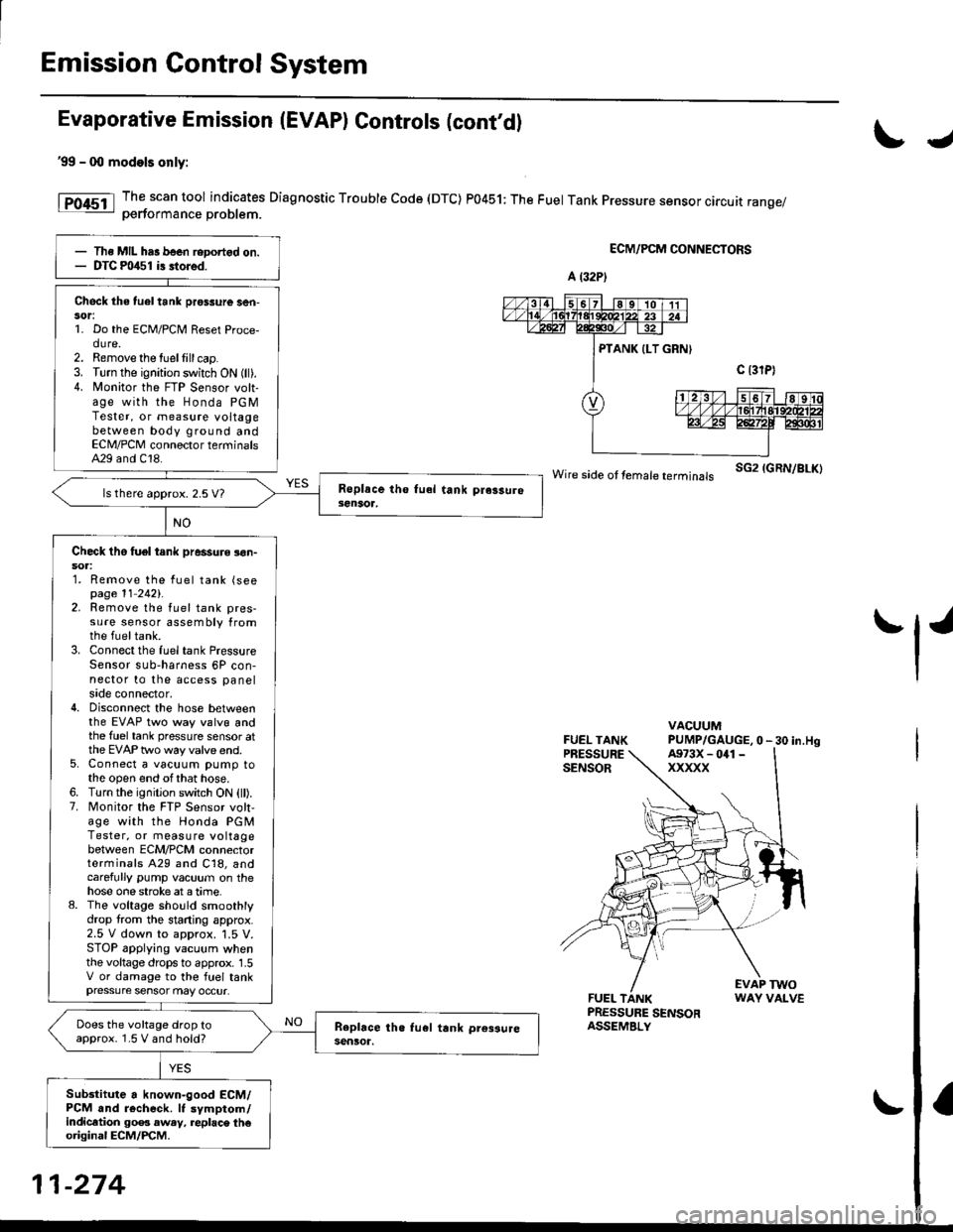
Evaporative Emission (EVAP) Gontrols (cont'd)
'99 - 0O models only:
The scan tool indicates Diagnostic Trouble Code (DTC) P0451: The Fuel Tank Pressure sensor circuit range/oerformance Droblem.
ECM/PCM CONNECTORS
wire side ot femare terminars sG2 IGRN/BLK)
FUEL TANKPRESSURESENSOR
VACUUMPUMP/GAUGE,0 - 30 in.Hg
FUEL TANKPRESSURE SENSORASSEMBLY
EVAP TWOWAY VALVE
IJ
tl'
Ths MIL has been reDortgd on.DTC m/$1 i3 stored.
Check the tuel tank pros3ure ser|-sor:1. Do the ECM/PCM Reset Proce-dure.2. Remove the tuellill cap.3. Turn the ignition switch ON (ll).4. N4onitor the FTP Sensor volt-age with the Honda PGMTester, or measure voltagebetween body ground andECN4/PCM connector terminalsA29 and C18.
ls there approx. 2.5 V7
Check tho tuel tank pressure !on-soa:1. Remove the fuel tank (seepage 11 2421.2. Remove the fuel tank pres-sure sensor assembly fromthe fueltank.3. Connect the fuel tank PressureSensor sub-harness 6P con-nector to the access panelside connector,4. Disconnect the hose betweenthe EVAP two way valvg andthe fuel tank pressure sensor atthe EVAP two way valve end.5. Connect a vacuum pump tothe open end ofthat hose.6. Turn the ignition switch ON (ll).7. Monitor the FTP Sensor volt,age with the Honda PGMTester, or measure voltagebetween ECM/PCM connectorterminals A29 and C18, andcarefully pump vacuum on thehose one stroke at a time.8. The voltage sho!ld smoothlydrop from the stading approx.2.5 V down to approx. '1.5 V.STOP applying vacuum whenthe voltage drops to approx. 1.5V or damage to the fuel tankpressure sensor may occur.
Does the voltage drop toapprox. 1.5 V and hold?
Sub3titute a known-good ECM/PCM and r6check. It symptom/indicltion 90e3 aw.y, replac\. th€original ECM/PCM.
A (32P)
A973X - 041 -
xxxxx
11-274
Page 552 of 2189

\
t,96 D16Y8 engine (coup6l,'9? Dl6Y7 engine (coupe: KL model, sedan: KL (LX) model)"g7 Dl6Y8 ongine (coupe: all mod-
els, sedan: KL model,'98-8ll modelsl 39 - 00 Dl5Y5 engine with M/Tl:
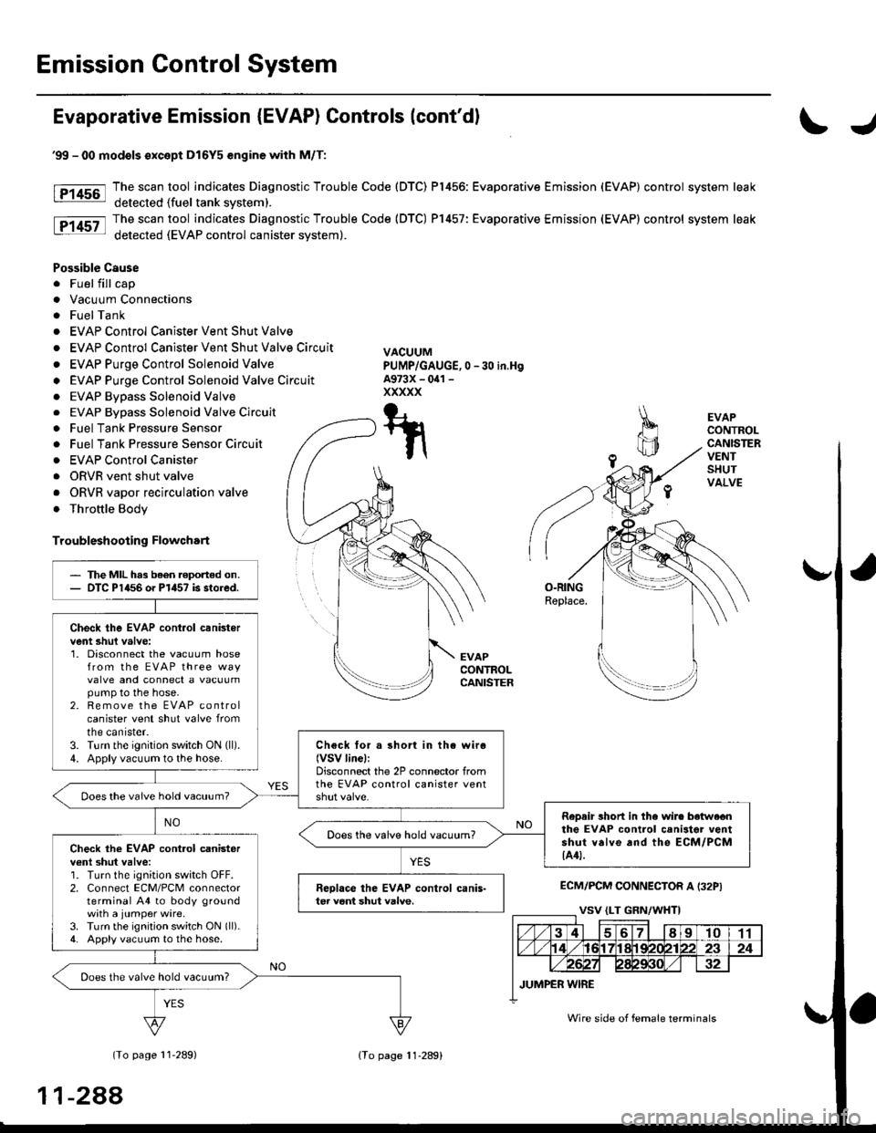
The scan tool indicates Diagnostic Trouble code (DTc) P1456: Evaporative Emission (EVAP) control system leak
detected (fuel tank sYsteml
The scan tool indicates Diagnostic Trouble Code (DTC) P1457: Evaporative Emission (EVAP) control system leak
detected (EVAP control canister system).
Fr4t6l
fF14s7
Possible Causs
. Fuel fill cap
. Vacuum Connections
. Fuel Tank
. EVAP Control Canister Vent Shut Valve
. EVAP Control Canister Vent Shut Valve Circuit
. EVAP Purge Control Solenoid Valve
. EVAP Purge Control Solenoid Valve Circuit
. EVAP Bypass Solenoid Valve
. EVAP Bypass Solenoid Valve Circuit
. Fuel Tank Pressure Sensor
. Fuel Tank Pressure Sensor Circuit
. EVAP Control Canister
. Throttle Body
Troublsshooting Flowchart
VACUUMPUMP/GAUGE,0 - 30 in.HgA973X - 041 -
xxxxx
I
EVAPCONTROL
.4, cANrsrER
re ./ VALVE
{S----r*::n
\(cont'd)
- The MIL ha3 been rePofted
on.- DTC P1456 or P1457 is stored.
Check the EVAP control canbtol
vent shut valve:1. Disconnect the vacuum hose
Irom the EVAP three waY
valve and connect a vacuurnpump to the hose.
2. Remove the EVAP control
canister vent shut valve Irofi
the canrster.3. Turn the ignition switch ON (lli
4. Apply vacuum to the hose.
Chock for . shon in the wire(VSv linel:Disconnect the 2P connector {rom
the EVAP control canister vent
Does the valve hold vacuum?
Repair short in the wir€ betwcen
the EVAP control canister vent
shut v.lve and tho ECM/PCM
tA29|.
Does the valve hold vacuum?
Check the EVAP control canister
vent shui valve:1. Turn the ignition switch OFF.
2. Connect ECM/PCM connectorterminal A29 to body ground
with a iumPer wire.
3. Turn the ignition switch ON (ll).
4. Applyvacuum to the hose
Reohce the EVAP control canis-
ter vent shttt valve.
Does the valve hold vacuum?
ECM/PCM CONNECTOR A {32P)
37I9t01t't2t3t5t6ItItt9202a2a
25aA
ILT GRN/W{T) I JUMPER WIRE
Wire side of femll terminals
(To page 11-284i(To page 11 284)
11-283
Page 553 of 2189

Emission Control System
Evaporative Emission (EVAPI Controls (cont'dl
1
EVAP CONTROLCANISTER VENT SHUTVALVE 2P CONNECTOR IC141}
lltrt+ rcl
o) (8LK/YErl
I
temale terminalsWire side ot
ECM/PCM CONNECTOR A (32PI
VSV ILT GRN/WHT}
'l'
Wiro side of lemaletgrminals
VACUUMPUMP/GAUGE,0 - 30 in.Hg4973X -
041 - XXXXX
(From page 1l-283)
{To page 1l-285}
Check the vacuum whon cold:1. Disconnect the vacuum hoseshown from the EVAP controlcanrster and connect a vacuumgauge to the hose,2. Start the engine and allow itto idle.NOTE: Engine coolant tem-perature must be below 154oF(68'C) or lVC switch OFF.3. Ouickly raise the engine speedto 3,000 rpm.
(From page l1-283)
Check for an open in tho wire(lGl line):1. Turn the ignition switch OFF.2. Disconnect the 2P connectorlrom the EVAP control canis-ter vent shut valve.3. Turn the ignition switch ON (ll).4. Measure voltage between theEVAP controlcanister vent shutvalve 2P connector terminalNo. 2 and body ground.
Repair open in the wire betwe€nthe EVAP control c.ni3tei ventshut valve and th6 No. 15 ALTER-NATOR SP SENSOR 17.5 Al fuse.
Cfisck tor an opon in the wire (VSVline):1. Turn the ignition switch OFF.2. Beconnect the 2P connectorto the EVAP control canistervent shut valve.3. Turn the ignition switch ON (ll).4. Measure voltage betweenECM/PCM connector termi-nals A29 and Al0.
Rep.ir open in the wire betwoonthe EVAP control canister ventshut valve and th€ ECM/PCMtA29t.
ls there battery voltage?
Replace th6 EVAP control canis-ter vent 3hut valve.
PGT (BLKI
:lI23l'ltl'l lelsl ro Ir I1213t6€lnltlr@/lzzl zs f il
25
11-284
Page 555 of 2189

Emission Control System
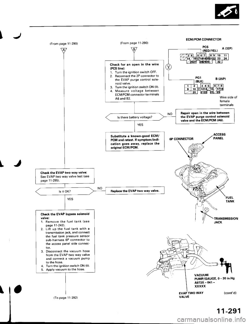
(From page 11 285)
Check lor an op€n in the wire{PCS line}:1. Turn the ignition switch OFF.2, Reconnect the 2P connector lothe EVAP purge control sole-noid valve.3. Turn the ignition switch ON (lll.4. Measure vo ltage betweenECM/PCM connector terminals415 and A]0.
Repai. op€n in the wire bGtweenthe EVAP purge control solenoidvalve and the ECM/PCM {A151.
Substitute a known-good ECM/PCM and retest. tf sympiom/indi-cation goes away, replac6 theoriginal ECM/PCM.
Evaporative Emission (EVAPI Controls (cont'd)
(From page 11'285)
(To page 'l1 287)
\.
ECM/PCM CONNECTOR A {32P}
PCS{RED/YEL)
PGl
{BLK)
Wire side oftemaleterminals
EVAP BYPASSSOLENOID VALVE
O.RINGBeplace.
PUMP/GAUGE,0 - 30 in.HgA973X -
041 -
xxxxx
EVAP TWO WAY VALVE
EVAP IWO WAY
Check the EVAP two way valvo:See EVAP two way valve test (seepage 11'294).
Replace tho EVAP two way valve.
Check the EVAP bypr$ 3olenoid
1. Disconnect the vacuum hosefrom the EVAP two way valveand connect a vacuum pumpto the hose.2. Turn the ignition switch ON lll).3. Apply vacuum to the hose.Check tor a short in the wire{2WBS linel:Disconnect the 2P connector fromthe EVAP bypass solenoid valve.Does the valve hold vacuum?
Repair short in the wire betwe€nEVAP bypass sol€noid valve andrhe ECM/PCM lA28).
Does the valve hold vacuum?
11-286
Page 557 of 2189

Emission Control System
Evaporative Emission {EVAP) Controls (cont'dl
\J
tF1456-l
tP14sz-l
EVAPCONTROLCANISTERVENTSHUTVALVE
O.RINGReplace.
EVAPCONTROLCANISTER
ECM/PCM CONNECTOR A I32PI
(To page 11'289)
'99 - 00 modols except Dl6Y5 engine with M/T:
The scan tool indicates Diagnostic Trouble Code (DTC) P1456: Evaporative Emission (EVAP) control system leak
detected (fuel tank svstem).
The scan tool indicates Diagnostic Trouble Code (DTC) P1457: Evaporative Emission (EVAP) control system leak
detected (EVAP control canister system).
Possible Cause
. Fuel fill cap
. Vacuum Connections
. FuelTank
. EVAP Control Canister Vent Shut Valve
. EVAP Control Canister Vent Shut Valve Circuit
. EVAP Purge Control Solenoid Valve
o EVAP Purge Control Solenoid Valve Circuit
. EVAP Bypass Solenoid Valve
0 -30 in,Hg
. EVAP Bypass Solenoid Valve Circuit
. Fuel Tank Pressure Sensor
. Fuel Tank Pressure Sensor Circuir
. EVAP Control Canister
. ORVR vent shut valve
. ORVR vapor recirculation valve
. Throttle Body
Troubleshooting Flowchart
VACUUMPUMP/GAUGE,A973X - oal -
xxxxx
T-t
t\
The MIL has been reported on.DTC P1456 o. P1457 is stored.
Check the EVAP cont.ol canistervent shul valve:1. Disconnect the vacuum hosefrom the EVAP three wayvalve and connect a vacuumpump to the hose.2. Remove the EVAP controlcanister vent shut valve fromtne canrster.3. Turn the ignition switch ON (ll).
4. Apply vacuum to the hose.Check for a short in the wiro(VSV linel:Disconnect the 2P connector fromthe EVAP control canister ventDoes the vaive hold vacuum?
RoDair 3hort in the wire botwe€nthe EVAP control canilter ventshut valve and the ECM/PCM{A4t.
Does the valve hold vacuum?Check the EVAP cont.ol canisterv€nl shut valve:1. Turn the ignition switch OFF.2. Connect ECM/PCM connectorterminal A4 to body groundwith a jumper wire.3. Turn the ignition switch ON (ll).
4. Apply vacuum to the hose.
Reolace the EVAP control canis-ter veni shut valve.
Does the valve hold vacuum?
Wire side of female terminals
11-288
lTo page 11-289)
Page 558 of 2189

\
EVAP CONTROLCANISTER VENT SHUTVALVE 2P CONNECTOR IC141I
Wire side of temale terminals
ECM,/PCM CONNECTORS
tG1IBLK/WHT}
A973X -
0/r1 - XXXXX
Wire side of femaletermrnats
\
?,T-t
fl
VACUUMPUMP/GAUGE, 0 -30 in.Hg
\(cont'd)
11-289
{From page l1 288}
{To page 11-290)
Ch€ck the vac[um when cold:1, Disconnect the vacuum hoseshown from the EVAP controlcanister and connect a vacuumgauge to the hose.2. Start the engine and allow it
to idle.NOTEi Engine coolant temperature must be below 154"F(68'C) or Ay'C switch OFF.3. Ouickly raise the engine speedto 3,000 rpm.
(From page 11-288)
Check for an open in tha wire(lGt linol:1. Turn the ignition switch OFF.2. Disconnect the 2P connectorfrom the EVAP control canis-ter vent shut valve.3. Turn the ignition switch ON lll).4. Measure voltage between theEVAP control canister vent shut
valve 2P connector terminalNo.2 and bodyground.
Repair open in the wire betweenthe EVAP control canister ventshut valve .nd the No. 15 ALTER-NATOR SP SENSOR {7.5 A)fu3e.
ls there battery voltage?
Ch€d( for an op€n in the wiie IVSVlinel:1. Turn the ignition switch OFF.
2. R€connect the 2P connectorto the EVAP control canistervent shut valve,3. Turn the ignition switch ON (ll).
4. Measure vo ltage betweenECM/PCM connector termi-nals A4 and 82.
Repair open in the wire bctweenthe EVAP control canistor ventshut valve and lhe ECM/PCM{44t.
ls there battery voltage?
Rcolaco tho EVAP control canis.t6r vent shut valvo.
a t32P)
-
Page 560 of 2189

IECM/PCM CONNECTOR
I
EVAP TWO WAYVALVE
Wire side oftemaleterminals
FUELTANK
(cont'd)
11-291
tn
VACUUMPUMP/GAUGE,0 - 30 in Hs
A973X - 041 -
xxxxx
(From page l1 290)
Check the EVAP two way valve:
See EVAP two way valve test (see
page 11-295).
Roplace the EVAP two way valve
Check the EVAP bypa$ solenoid
1. Remove the fuel tank (see
page 11-242J.2. LiIt up the fuel tank with a
transmission iack, and connect
the fuel tank pressure sensor
sub harness 6P connector to
the access panel side connec_
tor,3. Disconnect the vacuum hosefrom the EVAP two way valveand connect a vacuum PumPto the hose,4. Turn the ignition switch ON (ll)
5. Apply vacuum to the hose.
(To page 11 292)
(From page 11-290)
Check for an open in the wire
{PCS lin6):1. Turn the ignition switch OFF
2. Reconnect the 2P connector to
the EVAP purge control sole-
3. Turn the ignition switch ON {ll).4. Measu re voltage betweenEClr/PCM connector terminals
A6 and 82.
Ropair open in the wire betweenthe EVAP purge Gontrol solenoidvrlve and th6 ECM/PCM lA6lls there battery voltage?
Substitute a known-good ECM/
PCM rnd re{61. lf symptom/indi'
cation goes away, rePlace the
oiiginal ECM/PCM.
Page 680 of 2189

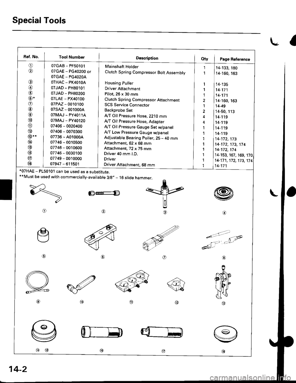
Special Tools
l.- a
Ref. No. Tool Number
o,6'\
€)
@)
@-
@
@
o
@
@
@
@..
@
@
@
@
@
07GAB - PF50101
07GAE - PG40200 or
OTGAE - PG4O2OA
07HAC - PK4010A
07JAD - PH80101
07JAD - PH80200
07LAE - PX40100
07PM - 0010100
07sM - 0010004
OTMAJ - PY4O1 1A
07MAJ - PY40120
07406 - 0020400
07406 - 0070300
07736 - A010004
07746 - 0010500
07746 - 0010600
07746 - 0030100
07749 - 0010000
07947 - 611501
Mainshaft Holder
Clutch Spring Compressor Bolt Assembly
Housing Puller
Driver Attachment
Pilot, 26 x 30 mm
Clutch Spring Compresso. Attachmenr
SCS Service Connector
Backprobe Set
IVT Oil Pressure Hose, 2210 mmAy'T Oil Pressure Hose, Adapter
Ay'T Oil Pressure Gauge Set dpanelA,/T Low Pressure Gauge WpanelAdjustable Bearing Pulter, 25 - 40 mmAftachment, 62 x 68 mm
Aftachment, 72 x 75 mmDriver 40 mm l.D.
Driver
Driver Attachment, 68 mm
I
1
1
1
I
1,l
'l
1
I
1
1
14-133, 180
14-160, 163
14-135
14-171
14-'�t7'l
14-160, 163
14-49
14-50, 113
r4-119
14- 1 19
14-119'14-1 19
14-172,173
14-172,'t73,114
14-172,174
14-153, 167. 169, 170
1+17 1 , 17 2, 173, 17
14-'t7'l
4
w
@o
*07HAE - P150101 can be used as a substitute.**Must be used with commercially-available 3/8,, _ 16 slide
E-E
@
@@
hammer.
=k
lalg
€)
ry
o
e
@
o
----a\\<-t-'- /\26
@@
@@@
aL
14-2