Page 382 of 2189

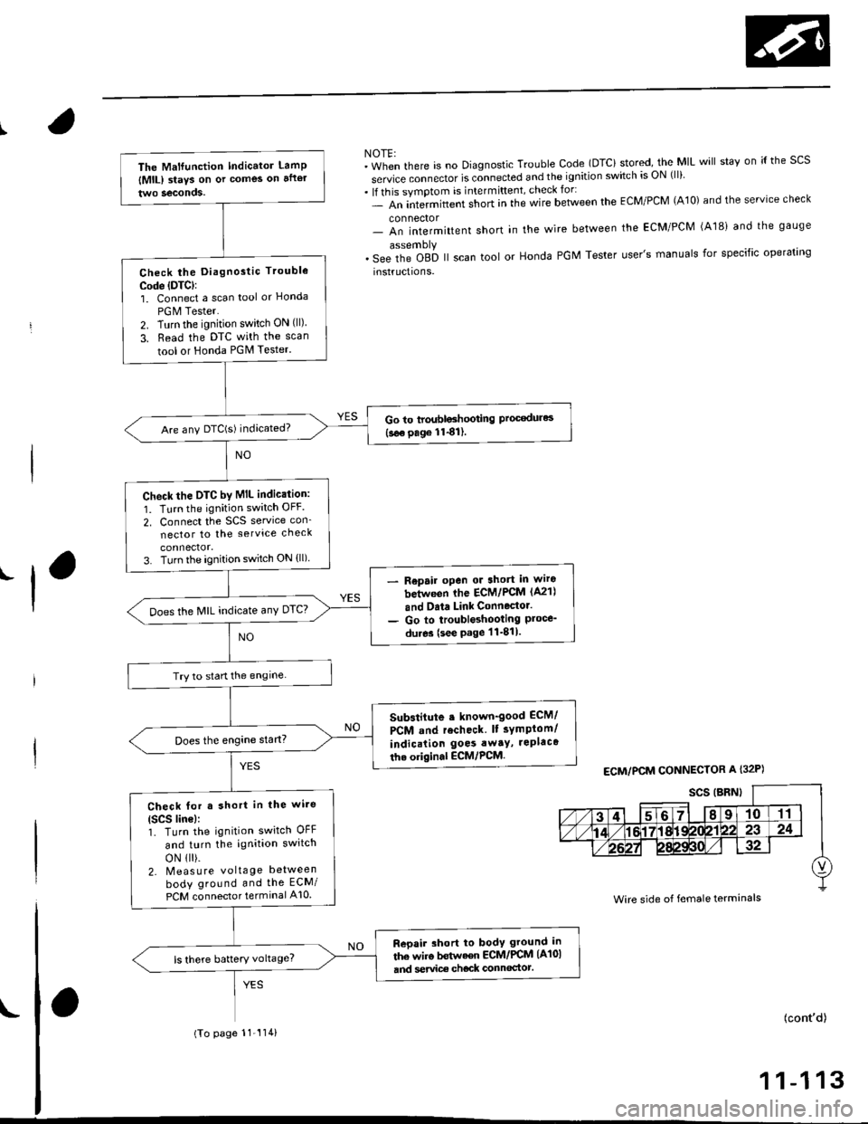
NOTE:"in-"n tf'"r" is no Diagnostic Trouble Code (DTCi stored, the MIL will stav on ;{ the scs
service connector is connected and the ignition switch is ON (ll)
. lf this symptom is intermittent, check for:- An intermittent short in the wire between the ECM/PCM (A10) and the service check
connector- An intermittent short in the wire between the ECM/PCM (A181 and the gauge
. s"" it'" Oab ll scan tool or Honda PGM Tester user's manuals for specific operating
instructions.
'l
ECM/PCM CONNECTOR A I32P)
Wire side of female terminals
The Malfunction Indicator LamP
lMlL) staYs on or comes on after
Check the Diagnostic Trouble
Code (DTC):
1. Connect a scan tool or Honcla
PGM Tester.
2. Turn the ignition switch ON (ll)
3. Read the DTC with the scan
tool or Honda PGM Tester.
Go to troubloshooting Proc€dures(see page 1141).Are any DTC(S) indicated?
check the DTC by MIL indic.tion:
1. Turn the ignition switch OFF
2. Connect the SCS service con_
nector to the service check
3. Turn the ignition switch ON (ll)
Repair open or 3hort in wiro
between ihe ECM/PCM (A21)
and Data Link Connector.
Go to troubleshooting Ploce_du.es (see page 11-811.
Does the MIL indicate anY DTC?
Try to start the engine
Substitute . known-good ECM/
PCM and recheck lt sYmptom/
indication goes awaY, rePlaca
th. original ECM,/PCM.
Check for a short in the wi.e(Scs line):1. Turn the ignition switch OFF
and turn the ignition switch
oN 1 ).2- Meas u re voltage between
body ground and the ECM/
PCM connector terminal A10
Reoair short to body ground in
the wiro bstwaen ECM/PCM (A101
and service ch€ck connoctot.ls there battery voltage?
(To page 11-'114)
(cont'd)
1 1-1 13
Page 388 of 2189

|'Manifold Absolute Pressure (MAP) Sensor
(;gg - OO Models except Dl6Y5 engine with M/T)
The scan tool indicates Diagnostrc Trouble Code (DTC) PO1O7: A low input (high vacuuml problem in the
Manifold Absolute Pressure (MAP) sensor'
The MAp sensor converts manifold absolute pressure into electrical signals and inputs the ECM/PCM'
OUTPUTVOLTAGE
lvl3.5
3.0
2.5
2.0
1.5
1.0
0.5
0(in.Hgl GAUGEREAOING(mmHgllq, 2oo 3q, (x, 5q) 6q) 700
MAP SENSOR 3P CONNECTOR IC114)
vccltYEL/RED)
Wire sido of fomalg tormin6ls
.-l
- The MIL h'3 been reported on- OTC P0107 b stor€d.
Problem verilication:
1. Turn the ignition switch ON {ll)
2. check the N4AP with the scan
tool.
lntermittent failuro, 3Ystom is OK
at this time. Ch€ck for Poor con'
nection3 or loose wiros at C111
IMAP sonsorl and ECM/PCM.
ls approx. 101 kPa (760 mmHg,
30 in.Hg)indicated?
Ch.ck for an opcn in wit. {vCC1
linel:1. Turn the ignition switch OFF
2. Disconnect the MAP sensor
connector.3. Turn the ignition switch ON (ll).
4. Measure voltage between the
MAP sensor connector No. 1
terminal and No 2 terminal
Repair opsn in the wirg botween
ECM/PCM (C19) rnd MAP seGor.ls there approx. 5 V?
(To page 11-120)
{cont'd)
1 1-1 19
Page 485 of 2189

ldle Control System
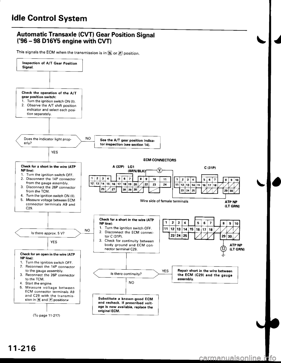
Automatic Transaxle (CVTI Gear Position Signal
('96 -98 D16Y5 engine with CW)
ATP NP{LT GRNI
INP
GBN)
This signals the ECM when the transmission is in @ or @ position.
Check the operation oI the A/Tgear position switch:1. Turn the ignition switch ON flt).2. Observe the A/T shift positionindicator and select each position separately.
See lhe A/T gear position indica-tor insp€ction {see sec{ion l/tl.
Check tor a short in the wir6 (ATpNP line):1. Turn the ignition switch OFF.2. Disconnect the 14P connectorIrom the gauge assembly.3. Disconnect the 26P connectorfrom the TCM.4. Turn the ignition switch ON fll).5. Measure voltage between ECMconnector terminals A9 andc29.
Check for a short in the wire lATpNP linell1. Turn the ignition switch OFF.2. Disconnect the ECM connector C (31P).
3. Check for continuity betweenbody ground and ECM connector terminal C29.
ls there approx. 5 V?
Check for an open in the wire lATpNP lina):1. Turn the ignition switch OFF_2. Beconnect the 14P connectorto the gauge assembly.3. Reconnect the 26P connectorto the TCM.4. Sta rt the engine.5. Measure voltage betweenECM connector terminals A9and C29 with the transmission in E and E posationt
Repair short in the wire betweenthe ECM {C291 and the gaugeassemblv,
Substitute a known-good ECMand recheck. lf prescribed volt-age is now avrilable, replace theo.iginalECM.
Wire side ot female terminals
2457I910
t112131a15151718
2321252930
ATP(LT io
(To page 11'217)
11-216
Page 486 of 2189
t
L
(From page 11-216)- Repair open in the wire
between the ECM {C291 and
lhe Ituge assomblv.- Repair open in the wire
betwoen the gauge assembly
and the A/T gea. Positionswitch.
ls there less than 1.0 V?
Chock for a short in the wite (ATP
NP line):Measure voltage between ECM
connector terminals Ag and C29
with the transmission in gear.
ReDair short in the wire be'tween
ECM (C291 and gauge a3somblY.ls there battery voltage?
A/T g€ar position signal is OK
LG1 IEBN/BLK)
ECM CONNECTORS
ATP NPWire side of female terminals (LT GRN)
Page 525 of 2189

Emission Control System
Exhaust Gas Recirculation (EGR) System (D16Y5 engine with GWI (cont'dl
lTl49il T_he scan tool indicates Diagnostic Trouble Code (OTC) P1491: A malfunction in the Exhaust Gas Recirculation- lEgh) svstem.
CvT lM/T see page 1l-2611:
J
EGR VALVELIFT SENSOR#16 HOSE
PUMP/GAUGE,0- 30 in.HsA973X-041-XXXXX
EGRVALVE
The MIL has been reoorted on.DTC P1491 is stoled.
Problem verification:1. Do the ECM/PCM Reset Proce-du re.2. Connect the SCS service con'
3. Start the engine. Hold theengine at 3,000 rpm with noload {in Park or neutral) untilthe radiator fan comes on,4. Drive the vehicle on the roadfor approx. 10 minutes. Try tokeep the engine speed in the1,700 - 2,500 rpm range.
Intermittonl failure, system is OKat this time. Check for Door con-nections or loose wires at, C144{EGR velve} and ECM/PCM.
ls DTC P l49l indicated?
Check fo. vacuum to ihe EGR
1. Disconnect the No. 16 hose fromthe EGR valve.2. Connect a vacuum pump/gauge to the hose.3. Start the engine and let it idle.
ls there any vacuum?
Check tor a malfunction in theEGR control solenoid valve:'1. Disconnect the EGR controlsolenoid valve 2P connector,2. Becheck the No. 16 hose for
Check vacuum hose routing o,the entire EGR svstem. lf hoserouting is OK, replac€ the EGRcontrol solenoidvalv6.
ls there any vacuum?
Substitute a known-good ECM/PCM and recheck. It symptom/indicalion goes away, replacethe original ECM/PCM.
(To page 11 257)
11-256
Page 526 of 2189
![HONDA CIVIC 1996 6.G Workshop Manual \EGR VALVELIFT SENSOR#16 HOSE
I
(From page 11-256)
EGR VALVE LIFT SENSOR3P CONNECTOR lC14.l)
zF vcczI- . ] IYEL/BLU)ll 2l3l---l-r_ 7 |
v-,, ISG2IGRN/BLK) I ^ II{Vts
ECM CONNECTOR D {16P)
PUMP/GAUGE,0 HONDA CIVIC 1996 6.G Workshop Manual \EGR VALVELIFT SENSOR#16 HOSE
I
(From page 11-256)
EGR VALVE LIFT SENSOR3P CONNECTOR lC14.l)
zF vcczI- . ] IYEL/BLU)ll 2l3l---l-r_ 7 |
v-,, ISG2IGRN/BLK) I ^ II{Vts
ECM CONNECTOR D {16P)
PUMP/GAUGE,0](/manual-img/13/6068/w960_6068-525.png)
\EGR VALVELIFT SENSOR#16 HOSE
I
(From page 11-256)
EGR VALVE LIFT SENSOR3P CONNECTOR lC14.l)
zF vcczI- . ] IYEL/BLU)ll 2l3l---l-r_ 7 |
v-,, ISG2IGRN/BLK) I ^ II{Vts
ECM CONNECTOR D {16P)
PUMP/GAUGE,0 - 30 in.Hs4973X-041-XXXXX
sG2(GRN/BLKIvcc2IYEL/BLU}
Wire side ol temale terminals
PCM CONNECTORS C (31P}'
YES
Wire side of female terminals
1
(cont'd)
1-257
Check fo. a mallunction in theEGF valv€:1. ldove the vacuum pump/gauge
to the EGR valve.2. With the engine at idle, apply
26.7 kPa (200 mmHg,8.0 in.Hg)
ofvacuum to the EGR valve.
Does the engine stall or runrough and does the EGR valvehold vacuum?
Check for an open in the wire
IVCC2linel:1. Turn the ignition switch OFF.2. Disconnect the EGR valve liftsensor 3P connector.3. Turn the ignition switch ON (ll).
4. Measure voltage between theEGR valve lift sensor 3P con'
nector terminals No. 3 and
No.2.
ls lhere approx.5 V?
Check for an oDen in the wire
{VCC2 line}:Measure voltage between theECM/PCM connector terminalsD10 and Dl1 (C18 and C28)*.
Rep.ir open in the wire betweenrhe EGR valve snd ECM/PCM
{Dl0 {C28)*).lsthere approx.5 V?
Sub3titute t known-good ECM/PCM end recheck. lt 3ymptom/indication goos eway, replaceth6 original ECM/PCM.(To page 1l-258)*: '99 - 00 models
Page 528 of 2189

I
I
Wire side of lemale terminals
PCM CONNECTORS C (31P)*
ECM CONNECTOR O {I5PI
Wire side of temale terminals
t
(From page 11-258)
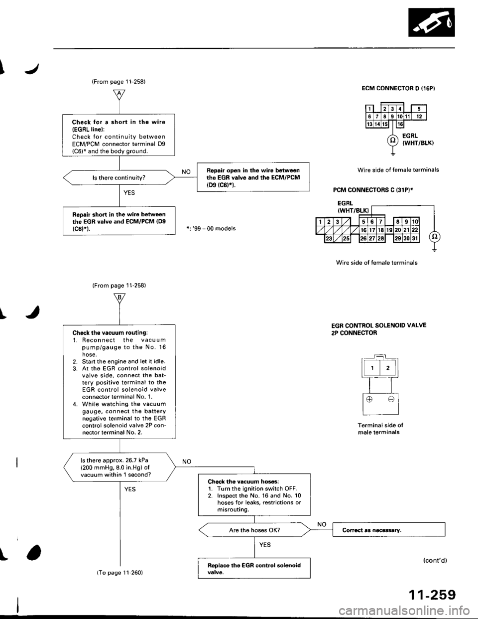
Check for a 3hort in the wire
{EGRL linel:Check for continuity betweenECM/PCM connector terminal Dg
Repair op€n in the wire betweenth6 EGR valve and the ECM/PCM(D9 tc6trt.
ReDair short in the wirc batweonthe EGR valve and ECM/PCM {Og(c5t*).
(From page 11-258)
11,260)
Check ths vacuum routing:'1. Recon nect the vacuumpump/gauge to the No. 16hose.2. Start the engine and let it idle.3. At the EGR control solenoidvalve side, connect the bat-tery positive terminal to theEGR control solenoid valveconnectot terminal No. 1.4. While watching the vacuumgauge, connect the batterynegative terminal to the EGRcontrol solenoid valve 2P con-nector terminal No. 2,
ls there approx.26.7 kPa
1200 mmHg,8.0 in.Hg) ofvacuum within 'l second?Chock the vlcuum hos6s:1. Turn the ignition switch OFF.2. Inspect the No. 16 and No. 10hoses for leaks, restrictions ormtsrouUng.
EGR CONTROL SOLENOID VALVE
2P CONNECTOR
Terminal side oImale lerminals
(cont'd)
11-259
Page 542 of 2189

J\
(From page 11-272)D16Y5 engine:
JUMPER WIRE
D16Y7, D16Y8 engine
VACUUMPUMP/GAUGE,
VACUUMPUMP/GAUGE,0 - 30 in.HgAs73x - 0il1 -
xxxxx
0 - 30 in.HgA973X -
otl -
xxxxx
I
EVAP CONTROLCANISTER
ECM/PCM CONNECTOH D I32PI
VACUUM/PBESSUREGAUGE0-4in.Hg07JAZ - 0010008
Wire side otfemale terminals
D16Y7, Dl6Y8 engine:
t
VACUUM/PRESSUREGAUGE0-4 in.Hgo?JAZ - 001fl)OB(cont'd)
11-273
PGl IBLKI
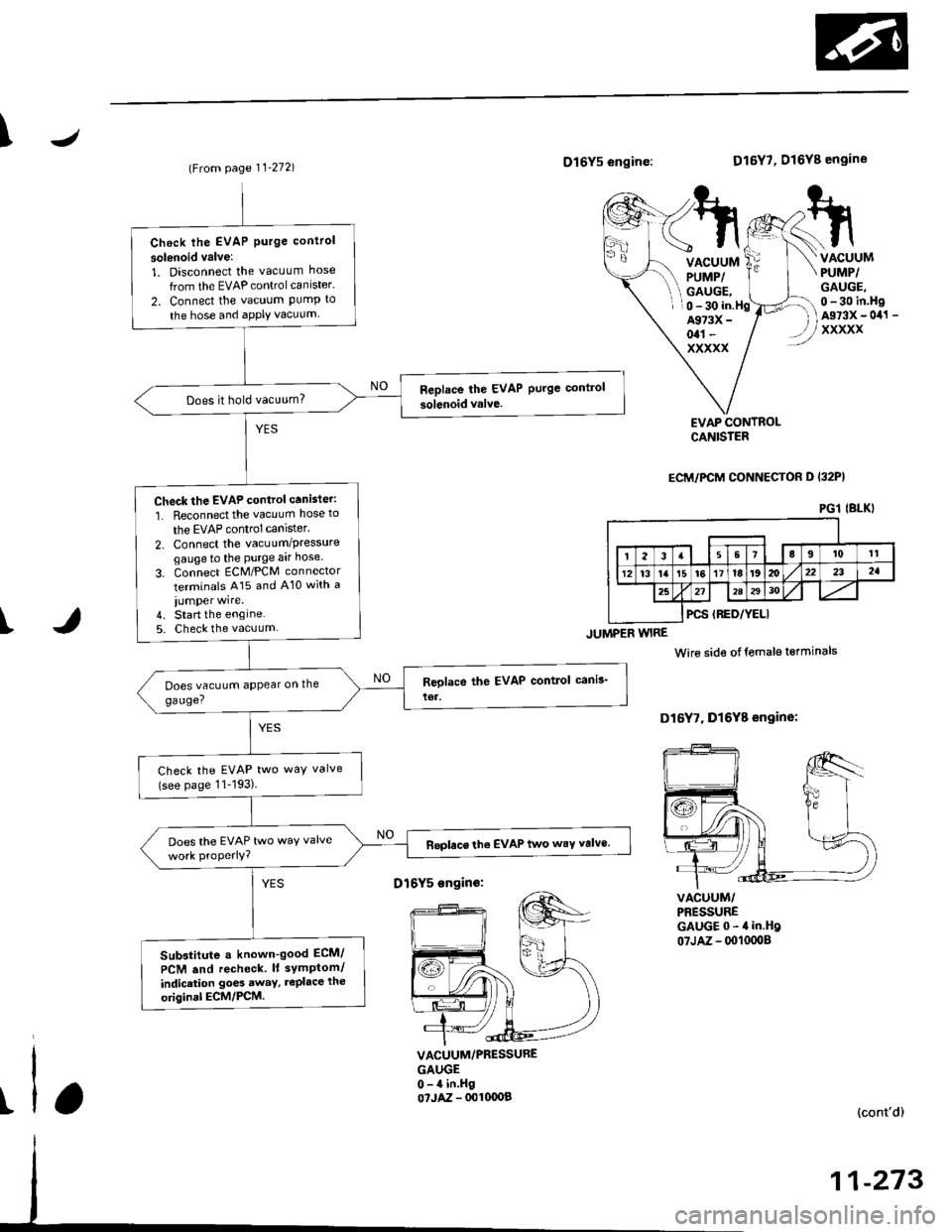
Check lhe EVAP Purge control
solsnoid valve:
1. Disconnect the vacuum hose
from the EVAP controlcanister'
2. Connect the vacuum PumP to
the hose and aPPIY vacuum
Does it hold vacuum?
Check the EVAP control canister:
1. Reconnect the vacuum hose to
the EVAP control canlster.
2. Connect the vacuum/Pressuregaugeto the Purge aar hose
3. Connect ECM/PCM connector
terminals A15 and A10 with a
iumper wire.4. Start the engine5. Check the vacuum
Check the EVAP two way valve(see page 11-193)
Does the EVAP two waY valveReplace the EVAP two wsY valve.
Sub3titute a known-good ECM/
PCM .nd recheck. lt symPtom/
indicrtion go6s away, rePlace the
original ECM/PCM.
D16Y5 sngin€: