Page 1683 of 2189
7.
8.
6. Remove the two screws, cut the wire harness, and
remove the actuator.
Record the terminal locations and wire colors'
Route the wire harness of the new actuator through
the hole in the bracket. Be sure to pass the wlre
under the bracket cliP.
BRACKET
9. Pass the connector boot over the wire harness
23-213
BLK/WHTi
,t
L,
.;{
I
oa
LT GRN I GRY
PNK
10, lnsert the terminals into the connector in the origi-
nal arrangement (recorded in step 7), as shown
Detow.
Right:
SLK/WHT*
BLU/REO'
": Canada '99 - 00 models
Apply tape to seal the intersection of the connector
boot and the wire harness.
Reassemble in the reverse order of disassembly Be
careful not to break the mirror when reinstalling it
to the actuator.
Reinstall the mirror assembly to the door.
Operate the power mirror to check that the actuator
works smoothlY.
Left:
11.
12.
13.
't 4.
PNK
Page 1720 of 2189
Gruise Control
Actuator Disassembly
ACTUAYOR CABLE
0
o
ACTUATOR BRACKET
WIRE SUPPORT BRACKET
ACTUATORTest, page 23 245
SOLENOID VAI-VESTest, page 23 247
SOLENOIDSEAL
I
+*RlAC
E
23-250
Page 1809 of 2189

E-
)I
Connect a 12 volt battery to the tool:
. lf the green light on the tool comes on, the aar-
bag igniter circuit is defective and cannot deploy
the airbag. Go to Damaged Airbag Special
Procedure.
. lf the red light on the tool comes on, the airbag is
ready to be deployed.
Push the tool's deployment switch. The airbag
should deploY (deployment is both highly audible
and visible; a loud noise and rapid inflation of the
bag, followed by slow deflation).
. lf the airbags deploy and the green light on the
tool comes on. continue with this procedure.
. l{ an airbag doesn't deploy, yet the green light
comes ON, its igniter is defective. Go to Dam-
aged Airbag Special Procedure.
!!@ During doployment, the airbag sssom'
bly can become hot enough to buln you. Wait thir'
ty minutes aftsr deployment belore touching tho
assembly.
Dispose of the complete airbag assembly. No part
of it can be reused. Place it in a sturdy plastic bag,
and seal it securelY,
CAUTION:
. Wear a fsce shield and gloves when handling a
deployed airbag.
. Wash your hands and rinse them well with
wat6r after handling. deployed airbag.
t('
24-71
7.
AIRAAG
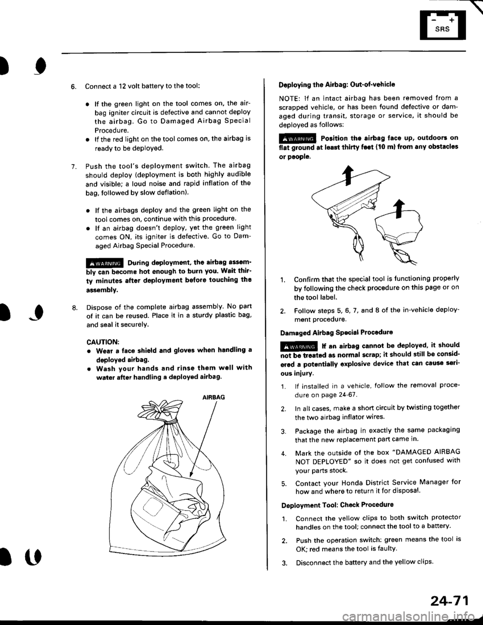
Doploying th6 Airbag: Out-of-vehicle
NOTE: lf an intact airbag has been removed from a
scrapped vehicle. or has been found defective or dam-
aged during transit, storage or service, it should be
deployed as follows:
@ Po3ition the airbag laca up, outdoors on
flat ground at lsast thirty f€€t (t0 ml from any obstacles
or people.
1. Confirm that the special tool is tunctioning properly
by following the check procedure on this page or on
the tool label.
2. Follow steps 5, 6, 7, and I of the in-vehicle deploy-
menl Drocequre.
Damaged Airbag Spacial Procedure
!@ r an airb.g cannot be deployed, it should
iiiTi-treatcd as normal scrap; il should still be consid-
srsd a potontially oxplosive device that can cau3o ssti-
ous iniury.
1. lf installed in a vehicle, lollow the removal proce-
dure on page 24-67.
2. In all cases. make a short circuit by twisting together
the two airbag inflator wires.
3. Package the airbag in exactly the same packaging
that the new replacement part came in.
4. Mark the outside of the box "DAMAGED AIRBAG
NOT DEPLOYED" so it does not get confused with
your Parts stock.
5. Contact your Honda District Service Manager for
how and where to return it for disposal.
Deployment Tool: Check Procedur€
1. Connect the yellow clips to both switch protector
handles on the tool; connect the tool to a battery.
2. Push the operation switch: green means the tool is
OK: red means the tool is faulty
3. Disconnect the battery and the yellow clips.
Page 1829 of 2189

In the "OHMS" range, the DVOM will measure
resistance between two points along a circuit.
Low resistance means good continuity.
Diodes and solid-state devices in a circuit can
make a DVOM give a false reading. To check
a reading, reverse the leads, and take a
second reading. lf the readings differ, the
component is affecting lhe measurement.
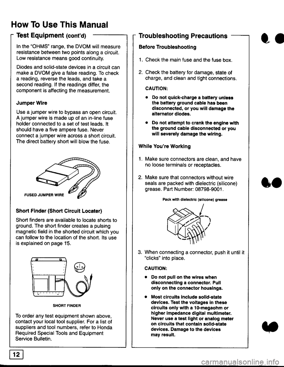
Jumper Wire
Use a jumper wire to bypass an open circuit.
A iumper wire is made up ot an in-line fuse
holder connected to a set of test leads. lt
should have a five amoere fuse. Never
connect a jumper wire across a short circuit.
The direct battery short will blow the fuse.
Short Finder (Short Circuit Locater)
Short finders are available to locale shorts to
ground. The short tinder creates a pulsing
magnetic field in the shorted circuit whlch you
can follow to the location of the short. lts use
is explained on page 15.
SHORT FINDER
To ordei any test equipment shown above,
contact your local tool supplier. For a list of
suppliers and tool numbers, refer to Honda
Required Special Tools and Equipment
Service Bulletin.
How To Use This Manual
Test Equipment (cont'd)
oa
Troubleshooting Precautions
Before Troubleshooting
1. Check the main fuse and the fuse box.
2. Check the battery for damage, state of
charge, and clean and tight connections.
CAUTION:
. Do not quick-charge a battery unlers
the battery ground cable has been
disconnected, or you will damage the
alternator diodes.
. Do not attempt to crank the engine wlth
the ground cable disconnected or you
will severely damage the wiring.
While You're Working
1. Make sure connectors are clean, and have
no loose terminals or receptacles.
2. Make sure lhat connectors without wire
seals are packed with dielectric (silicone)
grease. Part Number: 08798-9001 .
Pack wllh dlelectrlc (sillcons) greass
When connecting a connector, push it until it"clicks" into place.
Do not pull on the wires when
disconnecting a connector. Pull
only on the connector houslngs.
Most circuits Include solid-state
devlces. Test the voltages In these
circuits only with a lo-megaohm or
higher impedance digital multlm6ter.
Never use a test light or analog meter
on chcuits that contain solld-state
devices. Damage to the devices
may result.
oo
Page 1830 of 2189

Troubleshooting Tests
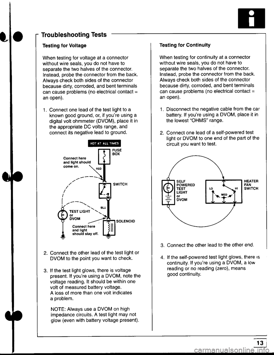
Testing for Voltage
When testing for voltage at a connector
without wire seals, you do not have to
seoarate the two halves of the connector.
Instead, probe the connector from the back.
Always check both sides of the connector
because dirty, corroded, and bent terminals
can cause problems (no electrical contact =
an open).
1 . Connect one lead of the test light to a
known good ground, or, if you're using a
digital volt ohmmeter (DVOM), place it in
the appropriate DC volts range, and
connect its negative lead to ground.
Connect the other lead of the test light or
DVOM to the point you want to check.
lf the test light glows, there is voltage
present. lf you're using a DVOM, note the
voltage reading. lt should be within one
volt of measured battery voltage.
A loss of more than one volt indicates
a problem.
NOTE: Always use a DVOM on high
impedance circuits. A test light may not
glow (even with baftery voltage present).
connecthere [fl5tst-tand light should IJJcomeon.
\" I
------{
/' BT swrrcH
lhl
l ----., I
6m""*soLENo,DI connect here I { lll
I 3#Ji8iL,* lj!!J
Testing for Continuity
When testing for continuity at a connector
without wire seals, you do not have to
separate the two halves of the connector.
lnstead. Drobe the connector Jrom the back.
Always check both sides of the connector
because dirty, conoded, and bent terminals
can cause problems (no electrical contacl =
an open).
1. Disconnect the negative cable from the car
battery. lf you're using a DVOM, place it in
the lowest "OHMS" range.
2. Connect one lead of a self-powered test
light or DVOM to one end of the part of the
circuit vou want lo test.
Connect the other lead to the other end.
lf the self-powered test light glows, there is
continuity. lf you're using a DVOM, a low
reading or no reading (zero), means
good continuity.
.t.
A
r3
Page 2189 of 2189
Connector ldentification and Wire Harness Routing
Connector
ot
Terminal
Numbor ot
CavitiesLocationConnects toNotest
t
Fuel Sub-Harness (GX)
uc/c
c682
c683
c684
6-GRN
2-GRY
3-N/A
2-GRY
Behind left side of rear seal
Left side of trunk
Middle ot trunk
Middle of trunk
Floor wire harness
Fuel lank internal solenoid valve
Fuel lank oressure sensor
Fuel tank temoerature sensor
FUEL SUB.HARNESS
203-48