Page 1281 of 2189

Troubleshooting
SymptomProbable Cause
Water leaks1. Clogged drain tube.
2. Gap between glass weatherstrjp and roof panel.
3. Defective or improperly installed glass weatherstrip.
4. Gap between drain seal and roof panel.
Wind noise'1. Excessive clearance between glass weatherstrip and roof panel.
Motor noise1. Loose motor.
2. Worn gear or bearing.
3. Cable assembly deformed.
Glass does not move, but motor turns'1. Clutch out of adjustment.
2. Foreign matter stuck between guide rail and slider.
3. lnner cable loose.
4. Cable assembly not attached properly.
Glass does not move and motor does not turn
{glass can be moved with moonroof wrench)
1. Blown fuse,
2. Faulty switch.
3. Battery run down.
4. Defective motor.
5. Faulty relay.
D
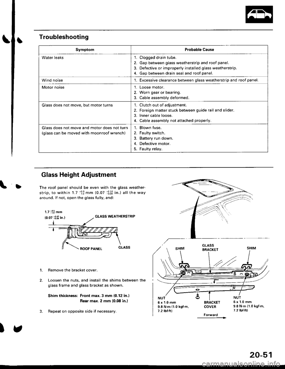
Glass Height Adjustment
The roof panel should be even with the glass weather-
strip, to within 1.7 :lr3 mm (0.07 :3:31 in.) all the way
around. lf not, open the giass fully, and:
GLASS WEATHERSTRIP
1. Remove the bracket cover.
Loosen the nuts, and install the shims between the
glass frame and glass bracket as shown.
Shim thickness: Front max.3 mm 10,12 in.l
Rear max. 2 mm 10.08 in.)
Repeat on opposite side i{ necessary.
)
5x1.0mm9.8 N.m 11.0 kgf m,7.2 rbtft)
SRACKETCOVEB
----------1>
6x1.0mm9.8 N.m {1.0 kgtm,7.2 tbf.ft)
1.7 tl.8 mm
{0.07 :3 3i in.}
20-51
Page 1285 of 2189

L
L
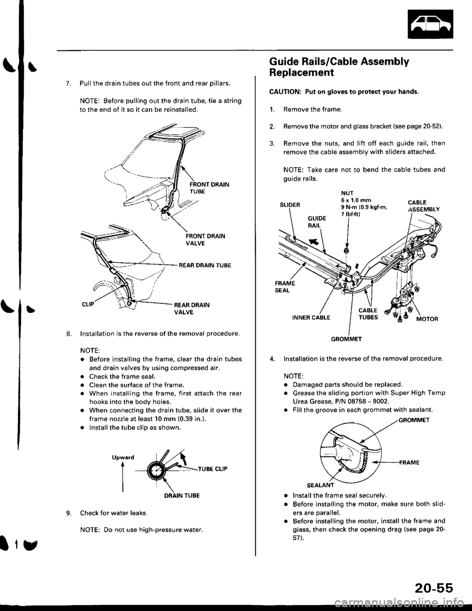
7. Pull the drain tubes out the front and rear pillars.
NOTE: Before pulling out the drain tube, tie a string
to the end of it so it can be reinstalled.
Installation is the reverse of the removal procedure.
NOTE:
. Before installjng the frame, clear the drain tubes
and drain valves by using compressed air.
. Check the frame seal.
. Clean the surface of the frame.
. When installing the frame, first attach the rear
hooks into the body holes.
. When connecting the drain tube, slide it over the
frame nozzle at least 10 mm (0.39 in.).
. Install the tube clip as shown.
UpwardI
I
I
TUBE CLIP
Check for water leaks.
NOTE: Do not use high-pressure water.
DRAIN TUBE
Ity
20-55
Guide Rails/Cable Assembly
Replacement
CAUTION: Put on gloves to protect your hands,
1. Remove the frame.
Remove the motor and glass bracket (see page 20-52).
Remove the nuts, and lift off each guide rail, then
remove the cable assembly with sliders attached.
NOTE: Take care not to bend the cable tubes and
guide rails.
Installation is the reverse of the removal procedure.
NOTE:
. Oamaged parts should be replaced.
. Grease the sliding portion with Super High Temp
Urea Grease, P/N 08758 - 9002.
. Fillthe groove in each grommet with sealant.
a
a
Install the frame seal securely.
Before installing the motor. make sure both slid-
ers are parallel.
Before installing the motor. install the frame and
glass, then check the opening drag (see page 20-
GROMMET
Page 1319 of 2189
Rear seal belt removal (3Dl:
1. Remove:
. Rear seat-back and rear seat cushion (see page
20_80)
. Rear center shelf and rear side shelf (see page
20_60)
. Rear trim panel and side trim panel (see page 20
60)
2. Remove the upper anchor cover
UPPER ANCHOR BOLT7/16-20 UNF32 N.m {3.3 kgf.m,2it lblft)
UPPERANCHOR
RETRACTOR
RETRACTOR BOLT7/16-20 UNF32 N.m 13.3 kgl.m.24 tbf.ft)
REAR SEATBELT
LOWEF
3.
7/r6-20 UNF32 N.m {3.3 kgl.m. 24 lbf.ftl
Remove all the anchor bolts and retractor bolt. then
remove the rear seat belt and retractor.
4. Installation is the reverse of the removal procedure.
NOTE:
. Check that the retractor locking mechanism func
tions as described on page 20-91.
. Make sure you assemble the washers and collars
on the upper anchor bolt as shown.
. Betore installing the anchor bolt, make sure there
are no twists or kinks in the rear seat belt.
Upper snchor boh construction:
COLLARS
Lower anchor bolt construction:
LOWER ANCHOR
TOOTHEDLOCK WASHER
(cont'd)
20-89
Page 1343 of 2189
Windshield Wiper Arms
and Linkage
Hatch latch/Lock cylinder:
NOTE: Remove the hatch trim panel (see page 20-63).
>: Bolt locationsA>,3
6x1.0mm I9.8 N.m i1.0 ksf m,l
1.2lbl.trl /
B>, 1
E6'cr
CYLINDER
6;:il;l,lr'.",
.r\
LOCK- r€ cYLTNDERL^ ! ./
rAs<.L ,/
\faa"El
rl
lnstallation is the reverse of the removal procedure.
NOTE:
. Grease the hatch latch.
. Make sure the hatch opens properly and locks
securely.
. Make sure the cylinder rod is connected properly.
Replacement
CAUTION: Pul on gloves to protect your hands
NOTE: Take care not to scratch the hood and body.
1. Remove the windshield wiper arms, then remove
the hood seal and cowl cover.
>: Clip locationsA>,9 B>,9WINOSHIELDWIPER ABMS
\j:_
Hw
u
cowl covER
Disconnect the connector, then
shield wiper linkage assemblY.
Japan/Canada-produced:
remove the wind-
10 x 1.25 mm18 N.m ll.8 kgf m,
(cont'd)
20-113
Page 1352 of 2189
Body ('97 model)
Front Seat Belt
Removal/lnstallatlon ....20-128
Rear Seat
RemovaUlnstallation ....20-126
Washer Tube
Windshield
fndex .......... 20-124
Outline of '97 Model Changes
The molding side seal was added.
The method of installing the rear seat cushion was changed (2Dl3D).
A middle floor gusset was added and the method of detaching the seat belt retractor was changed (2Dl3D)
The installation position of the washer tube was changed.
Page 1354 of 2189
Molding Side Seal
lnstallation
Glue the molding side seal to the windshield molding on
each side.
20-125
Page 1371 of 2189

Seat Belts
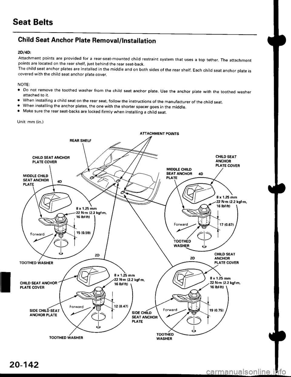
Child Seat Anchor Plate Removal/lnstallation
2DllDl
Attachment points are provided for a rear-seal-mounted child restraint system that usespoints are located on the rear shelf, tust behind the rear seat-back.The child seat anchor plates are installed in the middle and on both sides of the rear shelf.covered with the child seat anchor olate cover.
a top tether. The attachment
Each child seat anchor plate is
NOTE:
' Do not remove the toothed washer from the child seat anchor plate, Use the anchor plate with the toothed washerattached to it.
. When installing a child seat on the rear seat, follow the instructions of the manufacturer of the child seat.. When installing the anchor plates, the one with the shoner spacer goes in the middle.. Make sure the rear seat-backs are locked firmly when installing a child seat.
Unit: mm (in.)
REAR SHELF
CIIILD SEAT ANCHORPLATE COVER
MIDOLE CHILDSEAT ANCHOR
CHILO SEATANCHORPLATE COVER
CHILD SEATANCHORPLATE COVER
8 x 1.25 mm22 N.m 12.2 kgl m,
PLA
8 x 1.25 mm22 N.m 12.2 kgl.m,
I x 1.25 mm22 N.m 12.2 kgl.m,16 tbt.ftt
17 {0.67)
16 tbf.ft)
15 {0.s9)
WASHER
rl)
.t
TOOTHEO
ll ff*,".rd,',i"'"o*
SIDESEAT
I x 1,25 mmN.m {2.2 kgf.m.16 tbtftl
SIDE
16 tbf ftl
ANCHOR PLATESEAT ANCHORPLATE
ATTACHMENT POINTS
torward .
20-142
TOOTHED
12lO.47l19 (0.75)
Page 1414 of 2189
Heater Unit
Replacement (cont'dl
6.
7.
8.
9.
Remove the dashboard (see section 20).
Remove the heater duct (see page 21-37) or evapo-
rator (see page 22-28).
Disconnect the connectors from the mode control
motor and air mix control motor ('99 - 00 models),
then remove the wire harness clips and wire har-
ness from the heater unit. Remove the clip from the
heater duct, then remove the two mounting nuts
and the heater unit.
6x1.0mm9.8 N.m 11.0 kgl.m,7.2 lbf.ftl
HEATER UNIT
lnstall in the reverse order of removal. Make note of
the following items.
Apply sealant to the grommets.
Do not interchange the inlet and outlet heater
hoses. Make sure that the clamps are secure.
Refill the cooling system with engine coolant
(see section 10).
Connect all cables, and make sure they are prop-
erly adjusted (see page 21-44 (96 - 98 models)
or page 21-45 ('99 - 00 models)).
Make sure that there is no air leakage.
21-40