Page 151 of 2189

Cylinder HeadValve Seats
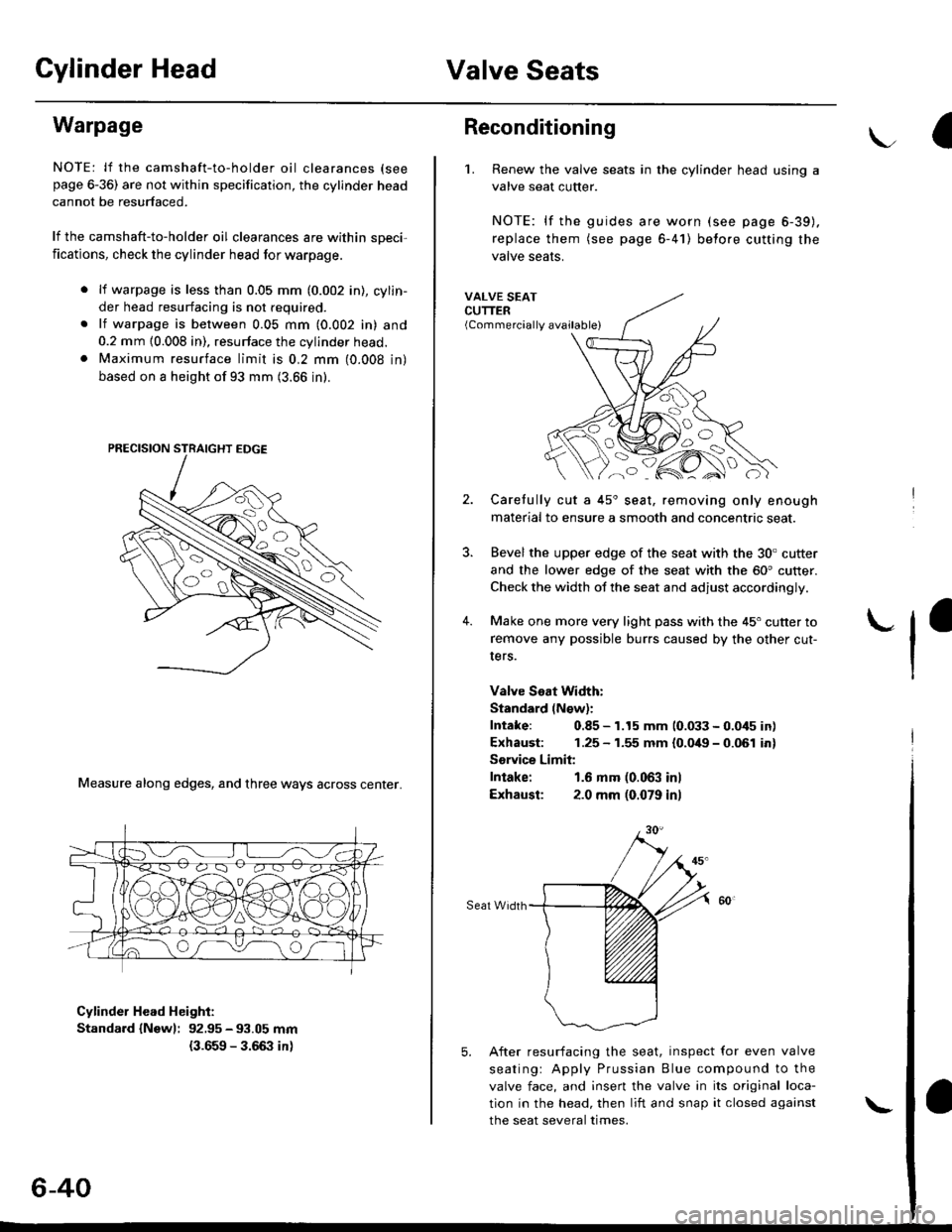
Warpage
NOTE: lf the camshaft-to-holder oil clearances (see
page 6-36) are not within specification, the cylinder head
cannot be resurfaced.
lf the camshaft-to-holder oil clearances are within sDeci,
fications, check the cylinder head lor warpage.
lf warpage is less than 0.05 mm (0.002 in), cylin-
der head resurfacing is not required.
lf warpage is between 0.05 mm (0.002 in) and
0.2 mm {0.008 in), resurface the cylinder head.
Maximum resurface limit is 0,2 mm (0.008 in)
based on a height of 93 mm (3.66 in).
Measure along edges, and three ways across center.
Cylinder Head Height:
Standard {Newl: 92.95 - 93.05 mm
{3.659 - 3.66:} in)
6-40
\
Reconditioning
'1. Renew the valve seats in the cylinder head using a
valve seat cutter.
NOTE: lf the guides are worn (see page 6-39).
replace them (see page 6-41) belore cutting the
valve seats.
VALVE SEATCUTTER(Commercially available)
2.
?
4.
Carefully cut a 45'seat, removing only enough
material to ensure a smooth and concentric seat.
Bevel the upper edge of the seat with the 30. cutter
and the lower edge of the seat with the 60' cutter.
Check the width of the seat and adjust accordingly.
Make one more very light pass with the 45" cutter to
remove any possible burrs caused by the other cut-
Iers.
Valve Seat Width:
Standard (N€w):
Intake: 0.85 - 1.15 mm 10.033 - 0.045 in)
Exhaust: 1.25 - 1.55 mm {0.049 - 0.061 in}
Sorvice Limit:
Intake: 1.6 mm (0.063 inl
Exhausl: 2.0 mm (0.079 in)
Seat Width
5. After resurfacing the seat, inspect for even valve
seatingr Apply Prussian Blue compound to the
valve face, and insert the valve in its original loca-
tion in the head, then liit and snap it closed against
the seat several times.
Page 157 of 2189

Cylinder Head
Installation (cont'dl
Position the camshaft correctly (see page 6-20).
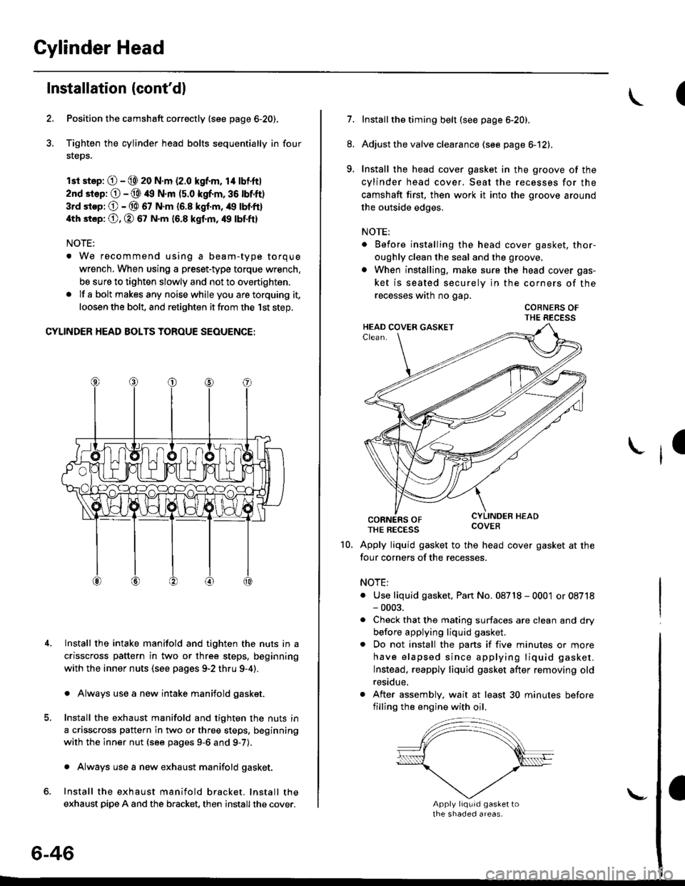
Tighten the cylinder head bolts sequentially in four
steps.
rsr st.p: O - @ 20 N.m (2.0 kgf.m, 14 lbf'ft|
2nd srep: O - @ 49 N.m (5.0 kgf.m, 36 tbtft)
3rd stop; O - @ 67 N.m {6.8 kgf.m, /r9 lbl'ft}
4th st6p: O, O 67 N.m 16.8 kgf.m, 49 tbf.ftl
NOTE:
. We recommend using a beam-type torque
wrench, When using a preset-type torque wrench.
be sure to tighten slowly and not to overtighten.
. If a bolt makesany noisewhileyou aretorquing it,
loosen the bolt, and retighten it from the 1st step,
CYLINDER HEAD BOLTS TOROUE SEOUENCE:
Install the intake manifold and tighten the nuts in a
crisscross pattern in two or three steps, beginning
with the inner nuts (see pages 9-2 thru 9-4).
. Always use a new intake manifold gasket.
Install the exhaust manifold and tighten the nuts in
a crisscross pattern in two or three steps, beginning
with the inner nut {see pages 9-6 and g-7).
. Always use a new exhaust manifold gasket.
Install the exhaust manifold bracket. lnstall the
exhaust pipe A and the bracket, then install the cover.
4.
6-46
\-
(
7.Installthe timing belt (see page 6-20).
Adjust the valve clearance (see page el2),
Install the head cover gasket in the groove of the
cylinder head cover, Seat the recesses for the
camshaft first, then work it into the groove around
the outside edges.
NOTE:
. Before installing the head cover gasket, thor-
oughly clean the seal and the groove.
. When installing, make sure the head cover gas-
ket is seated securely in the corners of the
recesses wath no gap.
COBNERS OFTHE RECESS
CORNERS OFTHE REcEss covEB
Apply liquid gasket to the head cover gasket at the
four corners of the recesses.
NOTE:
. Use liquid gasket, Pan No. 08718 - 0001 or 08718- 0003.
. Check that the mating surfaces are clean and dry
before applying liquid gasket.
. Do not install the parts if five minutes or more
have elapsed since applying liquid gasket.
Instead, reapply liquid gasket after removing old
residue.
. After assembly, wait at least 30 minutes before
filling the engine with oil.
8.
9.
I
10.
Page 160 of 2189
Special Tools
(\
Ref. No. I Tool NumberDescriptionOty Page Relerence
q oTHAH PJ7010B
g I 07JAA-001020A
g I 07JAB-0010204
I 07JAB - 0010404
g 07LAJ - PR3020A
|6) 07MAA - PR70100
g I ozvu,r - enu orzo
g 07MAF - PR9010A
g 07742 - 0010100(!D I 07757-PJ10104
Valve Guide Reamer,5.5 mm
Socket, 19 mm
Holder Handle
Pulley Holder Attachment. 50 mm
Air Stopper
Tappet Adjuster
Tappet Locknut Wrench
Valve Spring Compressor Attachment ExtensionValve Guide Driver, 5.5 mm
Valve Spring Compressor Attachment
1 I 6-81
1 659
1 6-59
1 ] 6-5s
1 I 6-55
1 6-57
1 6-57
1 J 6-77
1 6-80, 81
1 6-71
ta;
aL)'n
-=<-,,LE;;
(D
a
6-50
\-
Page 165 of 2189

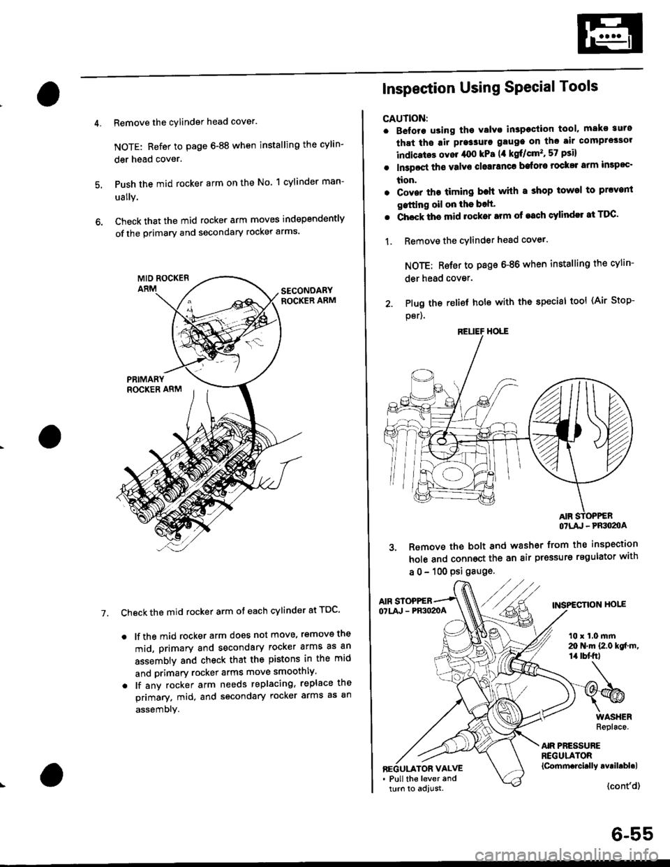
Remove the cylinder head cover.
NOTE: Refer to page 6-88 when installing the cylin-
der head cover.
Push the mid rocker arm on the No. 1 cylinder man-
ually.
Check that the mid rocker arm moves independently
of the primary and secondary rocker arms.
Check the mid rocker arm ot each cylinder at TDC'
. lf the mid rocker arm does not move, removs the
mid, primary and secondary rocker arms as an
assembly and check that the pistons in the mid
and primary rocker arms move smoothly.
. lf any rocker arm needs replacing, replace the
primary. mid, and secondary rocker arms as an
assembly.
7.
2. Plug the
per).
Inspection Using SPecial Tools
CAUTION:
. B€fore using tho Yalvo inspeciion tool, mako suro
that ths air pre3sure gauge on the air comprossor
indicatos ovor /rco kPa (,1 kgf/cm'�, 57 psi)
. In3poct ths valve closranca bafore rock$ arm impoc'
tion.
. Cover the timing beh whh I shop towel to prcvenl
gstting oil on the bolt'
. Chock ths mid rocker arm of each cylindll at TDC'
1. Remove the cYlinder head cover.
NOTE: Rsfer to page 6-86 when installing the cylin-
der head cover.
relief hole with the special tool (Air Stop-
OTLA' - PRSO2OA
3. Remove the bolt and washer from the inspection
hole and connoct the an air pressure regulator with
a 0 - 100 psi gauge.
AIF STOPPEBTNSPECTION HOIEOTLA' - PR3O2OA
t0 x 1.0 mrn20 N.m {2.0 kgf m,14 tbt'fr)
AIR PRESSUREREGULATOR{Cornm.rcirlly avril.bl.lBEGULATOR VALVE. Pull the lever andturn to adjust.{cont'd}
6-55
Page 167 of 2189

Valve Glearance
Adjustment
NOTE:
. Valves should be adjusted only when the cylinder
head temperaturs is less than 100'F (38'C)'
. After adjusting, retorque the crankshaft pulley bolt to
177 N.m (18.0 kgf'm, 130 lbt'ft)
1. Remove the cylinder head cover'
NOTE: Refer to page G86 when installing the cylin-
der head cover.
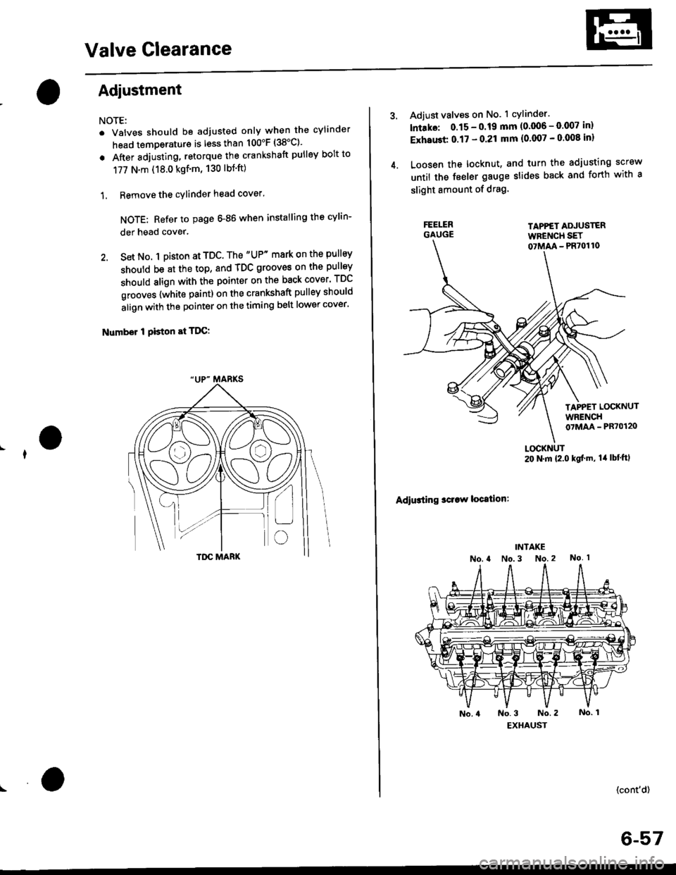
2. Set No. 1 pi$on at TDC. The "UP" mark on the pullsy
should be at the top, and TDC grooves on the pulley
should align with the pointer on the back cover' TDC
grooves {white paint) on the crankshaft pulley should
align with the pointer on the timing belt lower cover'
Number I Piston at TDC:
4.
Adjust valves on No. 1 cylinder.
lntako: 0.15 - 0.19 mm {0'006 - 0.007 in)
ExhaGt 0.17 - 0.21 mm {0'007 - 0 008 inl
Loosen the locknut, and turn the adjusting screw
until the feeler gauge slides back and forth with a
slight amount of drag.
TAPPET ADJUSTERWFENCH SET07MM - PR70110
TAPPET LOCKNUTWRENCH07MAA - PR70120
Adiusting sclaw location:
LOCKNUT20 N.m {2.0 kgf'm, lil lbt'ftl
(cont'd)
6-57
Page 168 of 2189
Valve Clearance
I
I
I
Adjustment {cont'd)
5. Tighten the locknut and recheck clearance.Repeat adjustment if necessary.
Rotate the crankshaft 180. counterclockwise(camshaft pulley turns 90'). The "Up" mark shouldbe on the exhaust side. Adjust valves on No. 3 cylin-der.
Number 3 piston at TDC:
FE€LER GAUGE
"UP- MARKS
6-58
7. Rotate the crankshaft '180. counterclockwise tobring No. 4 piston to TDC. The ,,Up,. mark shouldbe pointing straight down. Adjust valves on No. 4cylinder.
Number 4 piston at TDC:
8, Rotate the crankshaft 180. counterclockwise tobring No. 2 piston to TDC. The "Up., marks shouldbe on the intake side. Adjust valves on No. 2 cylin_der.
Number 2 piston at TDC:
L
Page 188 of 2189

Valve Seats
Reconditioning
1. Renew the valve seats in the cylinder
valve seat cutter.
NOTE: lf any guides are worn (see
replace them (see page 6-80) before
valve seats,
head with a
page 6-79),
cutting the
Carefully cut a 45o seat, removing only enough mate-
rial to ensure a smooth and concentric seat.
Bevel the upper edge of the seat with the 30" cutterand the lower edge of the seat with the 60. cutter.Check width of seat and adjust accordingly,
Make one more very light pass with the 45" cutter toremove any possible burrs caused bv the other cut-
ters.
Valve Seat Width:
Standard (Newl: 1.25 - 1.55 mm {0.0't9 - 0.061 in)Service Limii: 2.0 mm 10,08 inl
Sear Widrh
6-78
5. After resufacing the seat. inspect for even valveseating: Apply Prussian Blue Compound to thevalve face, and insert the valve in its original loca-tion in the head. then lift it and snap it closedagainst the seat several times.
PRUSSIAN BLUE COMPOUND
The actual valve seating surface, as shown by theblue compound, should be centered on the seat.. lf it is too high (closer to the valve stem), you mustmake a second cut with the 60. cutter to move itdown, then one more cut with the 45. cutter torestore seat width.
. lf it is too low (closer to the valve edge), you must
make a second cut with the 30. cutter to move itup. then one more cut with the 45. cutter to restoreseat width.
NOTE: The final cut should always be made withthe 45" cutter,
7. Insen the intake and exhaust valves in the head and
measure valve stem installed heioht.
Intaka Valve Stem Installed Height:
Standsrd lNaw): 37.465 - 37.935 mm(1./P50 - r.4935 inl
Sorvice Limit: 38.185 mm 0.5033 in)
Exhau3t Valv€ Stem Installed Height:
Standard (New): 37.165 - 37.6i|5 mm(1.46:t2 - 1.i1817 inl
Servico Limit 37.885 (1.4915 inl
lf valve stem installed height is over the service limit,replace the valve and recheck. lf it is still over the ser-vice limit, replace the cylinder head; the valve seat inthe h6ad is too deep.
(
Page 193 of 2189
Rocker Arms
lnstallation
1.
2.
3.
lnstall the rocker arms in the reverse order of
removal:
. Valve adjusting locknuts should be loosened and
the adiusting screw, backed off before installa-
tron.
. The component parts must be reinstalled in the
original locations.
lnstall the lost motion assemblies.
lnstall the rocker arms while inserting the rocker
arm shaft into the cylinder head
NOTE: Remove the rubber band after installing the
rocker arms.
12 mm BOLT
\
6-83
4. Clean and install the rocker shaft orifices with new
O-rings. lf the holes in the rocker arm shaft and
cylinder head are not in line with each other, screw
a 12 mm bolt into the rocker arm shaft and rotate
the shaft.
NOTE: The shapes of the rocker shaft orifices tor
the intake and exhaust are different. The orific'
must be installed in the proper locations.
INTAKE ROCKER
SHAFT ORIFICE
EXHAUST ROCKER Clean
SHAFT ORIFICE
O.RING
O