1996 HONDA CIVIC Head unit
[x] Cancel search: Head unitPage 48 of 2189

Unit of iength: mm (!n)
930 (9.5, 135)20012.0,zal
0.05 - 0.15 (0.002 - 0.006)
0.050 - 0.089 (0.002 - 0.004)
0.0310.001)max.33.088 (1.3027i
36.261 {1.4278)34.978 (1.3771)
32.785 {1.2907)35.720 (1.4063)
34.691 (1.3658)
u*u lo.r,ool5.420 (0.2134)
0.08 (0.003)
0.11 (0.004)
2.0 (0.08)
2.0 (0.08)
38.185 (1.5033)
37.885 (1.4915)
250 rpm (min riand Nominal
wide open throttle Minimum
kPa (kqf/cm'�, psi) Maximum variation
End play
Camshaft-to holder oil clea€nce
Total runoutCam lobe height lN PrimaryMidSecondaryEX PrimaryMidSecondary
0.15 - 0.19 (0.006 - 0.007)*
0.17 - 0.21 (0.007 - 0.008)*
5.475 - 5.485 10.2156 - 0.2159)
5.450 - 5.460 (0.2146 - 0.2150)
0.025 - 0.055 (0.0010 0.0022)
0.050-0.080 (0.0020 - 0.0031)
Valve clearance
Valve stem O.D.
Stem-to-guide clearance
INEXINEXINEX
1.25 - 1.55 {0.049 - 0.061)r.25 - 1.55 (0.049 - 0.061)
37.465 - 37.935 (1.4750 - 1.4935)
37.165 - 37.635 (1.4632 - 1.4817)
INEXINEX
width
Stem installed height
40.92 (1.611)*'
40.91 (1.6111"
36.71 (1.415)
41.96 (1.652)*r
4 r.94 (1.651)*'
free t*gth lN OUTER
5.51 - 5.53 (0.217 - 0.218)5.51 - 5.53 (0.217 - 0.218i12.55 - 13.05 (0.494 0.5'�j4)
12.55 - 13.05 (0.494 - 0.514)
LD. lNEX
Installed height lNEX
0.025 - 0.052 (0.0010 0.0020)
o.o2s - 0.052 {0.0010 0.0020)
Cylinder Head/Valve Train(816A2 engine) - Section
MEASUREMENTSTANDARD INEW)SERVICE LIMIT
*: Measuring point between camshaft and rocker arm'*1: NTHON H;TSUJO manufactured vatve spring. *2: CHUO HATSUJO manutactured valve spnng.
3-3
Page 52 of 2189

Unit of length: mm (in)
Fuel and Emission - Section
MEASUREMENTSTANOARO (NEW)
260 310 (2.7 - 3.2, 38 - 46)
260 - 310 (2.7 - 3.2, 38 - 46i
260 - 310 (2.7 - 3.2, 38 - 46)
210 - 320 Q.A - 3.3, 40 - 47 1
45 {11.9, 9.9)
M/T (neutral) I A/T or C\.T (lE or fd positioni
Fuel paessure
regulator
Pressure wilh fuel pressure regulator vacuum hose
disconnected kPa (kgvcm'�, Psi)D16Y5D 16Y7D16Y881642
FueltankCapacity I (US gal, lmp gal)
E ngineldle speed rpm
016Y5D16Y7D16Y8816A2
u.s.A.CanadaU,S,A.Canada
670 1 506701 50670150700 t 50
7501 507501 507501 50
700 t 50700 I 507001 50750150750 r 50
ldle CO %0.1 max.
Clutch - Serrtion 12
MEASUREMENTSTANDARD {NEWI I SERVICE LIMIT
Clutch pedalPedal height to floor
StrokePedal play
Disengagement height to floorto carpet
16s (6 1/2)130 140 (5 1/8 5 1/2)
12 -21 t1l2 - 13/16183 (3 1/4)44 (1 3/4) min. Reference
FlywheelClutch surface ruoout
Rivet head depthThickness
0.05 (0.002) max.0.15 (0.006)
Clutch disc1.3- 1.9 (0.05 - 0.07)
8.5 - 9.1 (0.33 - 0.36)
0.2 {0.01)5.5 (0.22)
Pressure plateWarpageDiaphragm spring fingers alignment
0.03 (0.001) max0.6 (0.02) max
0.15 (0.006)
1.0 (0.04)
Lro
3-7
lfllHlllllllllrltllli[
Page 140 of 2189

13. Remove the upper radiator hose' heater hose and
water bYPass hose
WATEREYPASSHOSEUPPERRADIATORHOSE
14.
HEATERHOSE
Remove the engine wire harness connectors and
wire harness clamps from the cylinder head and the
intake manifold.
o Four fuel injector connectors
. Engine coolant temperature (ECT) sensor con-
nector
a
a
a
ECT switch connector
ECT gauge sending unit connector
Throttle position sensor connector
Manitold absolute pressure (MAP) sensor con-
nector
Primary heated oxygen sensor (primary HO2S)
connector
Secondary heated oxygen sensor (secondary
HO2S) connector (D16Y7 engine)
Exhaust gas recirculation (EGR) valve lift sensor
connector (D16Y5 engine)
. VTEC solenoid valve connector (Dl6Y5, D16Y8
engrnes)
. VTEC pressure switch connector (D16Y5. D16Y8
engrnes,
. ldle air control (lAC) valve connector
15.Remove the spark plug caps and distributor from
the cylinder head.
Remove the uPPer bracket.
NOTE:
. Use a jack to support the engine before the
upper bracket is removed.
. Make sure to place a cushion between the oil
pan and the jack.
12 x 1.25 mm
74 N.m {7.5 kgf m.
sil lbl.ftl
UPPERBRACKET
'17. Remove the cylinder head cover'
CYLINDERHEAD COVER
(cont'd)
6-29
Page 148 of 2189

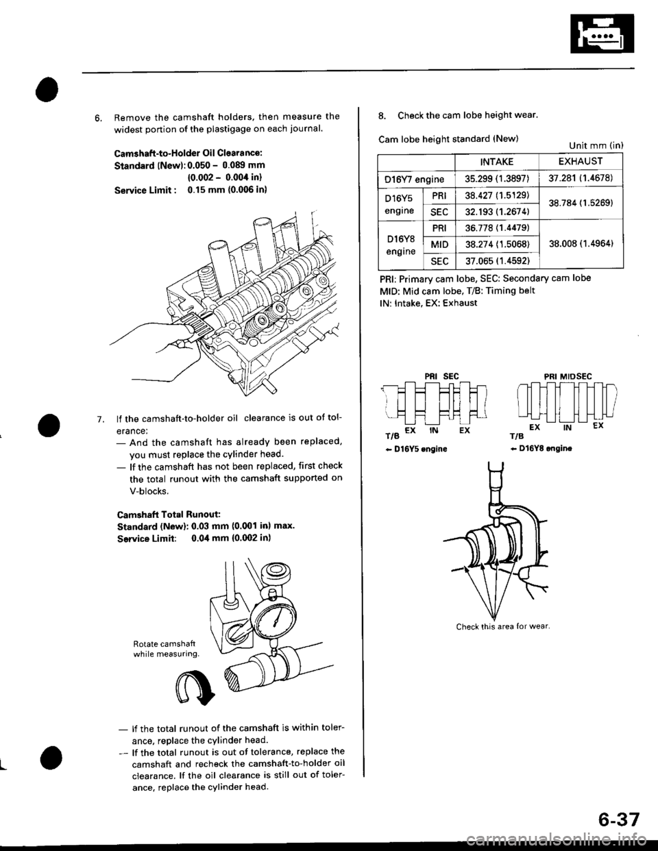
6, Remove the camshaft holders. then measure the
widest ponion of the plastigage on each journal.
Camshaft-to-Holder Oil Clearance:
Standard lNew):0.050 - 0.08!t mm
{0.002 - 0.004 in}
Service Limit : 0.15 mm {0.006 in)
lf the camshaft-to-holder oil clearance is out ot tol-
erance:- And the camshaft has already been replaced,
you must replace the cylinder head.
- lf the camshaft has not been replaced, first check
the total runout with the camshaft supported on
V-blocks.
Camshaft Total Runout:
Standard (New): 0.03 mm (0.001 inl max.
Service Limit: 0.04 mm {0.(X)2 in)
-7.
Rotate camshattwhile measuring.
L
- lf the total runout of the camshaft is within toler-
ance, replace the cylinder head.
- lf the total runout is out of tolerance, replace the
camshaft and recheck the camshaft-to-holder oil
clearance. lf the oil clearance is still out of toler-
ance. replace the cylinder head.
INTAKEEXHAUST
O16Y/ engine35.299 (1.3897)37.281 (1.4678)
D16Y5
engrne
PRI38.427 11.5129138.784 (1.5269)
SEC32.193 (1.2674)
D l6Y8
engrne
PRI36.77811.44791
38.008 (1.4964)MID38.274 (1.5068)
sEu37.065 (1.4592)
8. Check the cam lobe height wear.
Cam lobe height standard (New)
t/g a* rN Ex
- D16Y5 engine
PRI; Primary cam lobe, SEC: Secondary cam lobe
MtD: Mid cam lobe. T/B: Timing belt
lN: Intake, EX: Exhaust
PRIsEcMIDSEC
rts
- Dl6YE ongine
Unit mm (in)
Check this area {or wear.
6-37
Page 179 of 2189

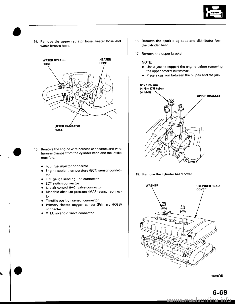
WATER BYPASS
HOSE
14. Remove the upper radiator hose, heater hose and
water bvpass hose.
HEATER
Remove the engine wire harness connectors and wlre
harness clamps from the cylinder head and the intake
manifold.
Four fuel injector connector
Engine coolant temperature (ECT) sensor connec-
tor
ECT gauge sending unit connector
ECT switch connector
ldle air control (lAC) valve connector
Manifold absolute pressure (MAP) sensor connec-
tor
Throttle position sensor connector
Primary Heated oxygen sensor (Primary HO2S)
connecror
VTEC solenoid valve connector
15.
a
a
a
a
a
\
16.
17.
Remove the spark plug caps and distributor form
the cylinder head.
Remove the upper bracket.
NOTE:
. Use a jack to support the engine before removing
the upp€r bracket is removed.
. Place a cushion between the oil panandthejack.
12 x 1.25 fin74 N.m 17.5 kgtm,
UPPER BRACKET
18. Remove the cylinder head cover.
{cont'd)
6-69
Page 361 of 2189

Troubleshooting
Engine/P_o,wertrain Control Module Terminal Arrangement('99 - 00 Models except Dl6Y5 engine with M/Tl
ECM/PCM CONNECTOR A (32P)Wire side ot temale terminalsNOTE:Standard battery voltage is l2 V
ECM/PCM CONNECTOR A I32PI
Sign!l
3BLU2WSS (EVAP 8YPAsS SOLENOIDDrives EVAP bypass solenoid vatve,With gn'tion swnch ON (lll banery votlage
LT GRN/I/VIITVSV {EVAP CONTNOL CANISTERVENTSHUTVALVE]Drives EVAP controt ca n isrer v€nt shutWilh ignilion switch ON {tl): b€ttery vottage
8LU/GNNC8S (CRUISE CONTSOL SIGOown shift signal inpot lrom c.uise conrrolWhen crurss control is used:purses
68ED/YELPCS {EVAP PURGE CONTROLSOTENOIOVALVE)Drives EVAP purge conrrol sotenoid vatve.With engine running, engine cootant, betow r54.F (6a,C):
With engine.unning, €ngine coolant, abov€ 154.F(68'C): duty conlrolled
YELATPD {AT GEAR POSITIONSWITCH)ootects A/T gear posnion swilch s,gnar.In otherthan @ posilion: Apprcx. 5 V
8BLK,IflHTSO2SHTC (SECONDARY HEATED OXYGEN SENSOS HEATEFCONTFOL)
Drives sscondary h€ared oxygen senso.Wilh isn,rion swirch ON (ll):banery votraseWith lully warm6d dp€ngire runn'ng:dury controled
LT GRNATPNP (AT GEAF POSITIONSWITCH)oereds A/T 9€a r position switch signat.In Parr or neulrsl:0 VIn anyother position approx.5 v
t088NSCS (SERVICE CHECK SIGNAL)Oetects ssruice check connecror signal(the signalcausing a OTC indication)with rh€ t6rminal connected: 0 vWith the rerm ina I disconneded: abour 5 V of ban€ry
GNN/BIKD4IND (D4INDICATON]Drives Oa indicaio. lighr.With D4 indicator lightturned ON: O VWith D4 indicator lightturned OFF: battery vo ttageG8N/YETFTF (FUEL PUI\,4P SELAY)Orivos tuel pump relay,0V for two s€conds lfrer turnrng rgnilior swtcn ON(ll), then batt€ry voltage11BTI(REDACC (Al/C CTUTCH SELAY)Drives A./C clutch reray.With compressor ON:O VWilh comp.ssor OFF; battery vottage18GFN/OFNMI! (A,IAIFUNCTION INDICA.TOF LIGHT)With MlLturned ON:0 VWith l\,llL tornod OFF|batrery votrsge198tuNEP (ENGINE SPEED PUTSEIOulputs6ngine speed pulse,Wilh engin6.unning: putses
20GFNFANC {SADIATOR FAN CONTnoL)Orives radiarortan relay.Wirh r.distor t6n running:OVWith radiatortan stopped: banery vottage21ELUA/ELK LINESends and r€ceives s.an lool signal.With ignition switch ON (ll):p!ts€s
22'lBLUATP L {AT GEAS POSITIONswtTcH)Oelocis A"/T gear posirion switch siSnat.In othfflhan E position: Apprcx. 5 V
23SHO25 (SECONOARY HEATEDOXYCEN SENSOR, SENSOF 2)Detects secondsry hoar€d oxygen sensorWith lhronle f! lly or'6ned from idte with fu ywarmod up engine: above 0.6 vWiih th.onl6 quickb, closd:below 0,4 V24STS ISTAFTEN SWITCH SIGDebcrs staner switch signat.Wirh srarterswitch ON (tttJ: batteryvottogeWith sraftsr cwirch OFF:0 V26GFNPSPSW iPlS PNESSURESWITCII SIGNAL)Derecrs PSP switch signat.Atidle with steoring wheolin srraightahead position: O VAt idl6with steering wheetal fult lock: barery vo ttags27BLU/REOACS (AJC SWITCH SIGNALJOer*ts ,ay'C swirch signat.Wiih ty'C switch ON;0VWilh Ay'C switch OFF|aboor 5VWHT/REDSLU iINTERLOCK CONTROIUNIT)Drivos interloct control unit.With ignltion switch ON (ll)and brake pedaldepresed: batlory volrage29LT GRNPTANK (FUEL TANK PFESSUEESENSOR)Oer6ds lu€l tank pr€ssura sonsor signat.Wilh ig.rrrd swirch ON rttr and fuetti
cap ooen6d.
30GRN/FEOEr (ELOIWith parking lighlsrurned on ar idteiaboui 2.5- 3.S VWirh low beam he€dlig hts turnqd on ai idts: aboul 1.52.5 V32GRN/'WHTAKSW (BFAKE SWITCH)Detets brak€ swrtch signEt,With brake pedal r6l€ased:0 VWhh brake pedaldepres*d: battery voltEse'1:A./T (D16Y7, D16Y8 engine)*2: rvt/T13: CVT (D16Y5 engine)
11-92
Page 1104 of 2189

Steering Gearbox
Removal {cont'dl
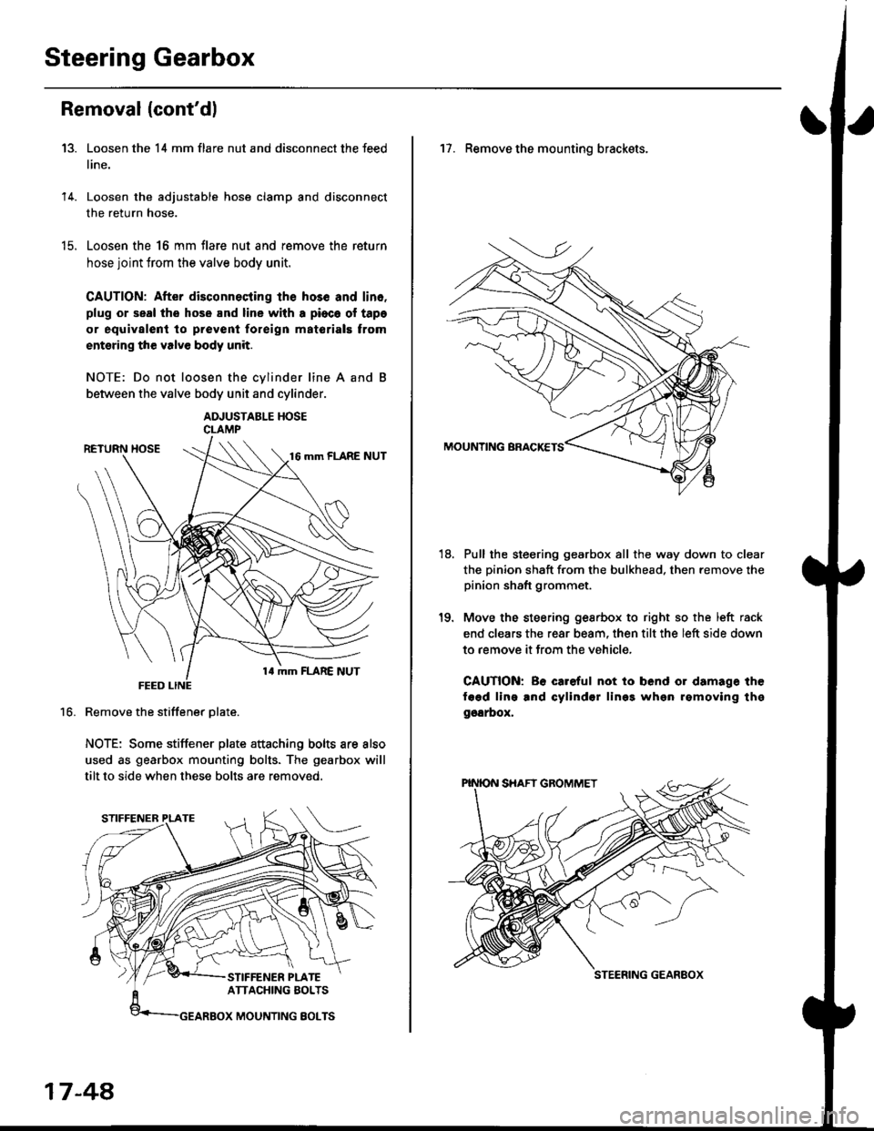
Loosen the 14 mm flare nut and disconnect the feed
line.
Loosen the adjustable hose clamp and disconnect
the return hose.
Loosen the 16 mm flare nut and remove the return
hose joint trom the valve body unit.
CAUTION: After disconnecting lhe hos6 and lin6.
plug or seal the hose and line with a pioca ol tapa
or equivalent to prevenl foreign matorials trom
entsring the valve body unit.
NOTE: Do not loosen the cvlinder line A and
between the valve body unit and cylinder.
ADJUSTABLE HOSECLAMP
Remove the stiffener Dlate.
NOTE: Some stiffener plate attaching bolts are also
used as gearbox mounting bolts. The gearbox will
tilt to side when these bolts are removed.
13.
14.
t9.
16.
17-48,
17. Remove the mounting brackets.
Pull the steering gearbox all the way down to clear
the pinion shaft from the bulkhead. then remove the
pinion shaft grommet.
Move the steering gesrbox to right so the left rack
end clears the rear beam, then tilt the left side down
to remove it from the vehicle,
CAUTION: Be careful not io bend or damage the
fagd ling and cylindsr lin99 whgn rgmoving thg
ggarbox,
18.
STEERING GEANEOX
Page 1175 of 2189

Master Cylinder/Brake Booster
IRemovaUlnstallation
CAUTION:
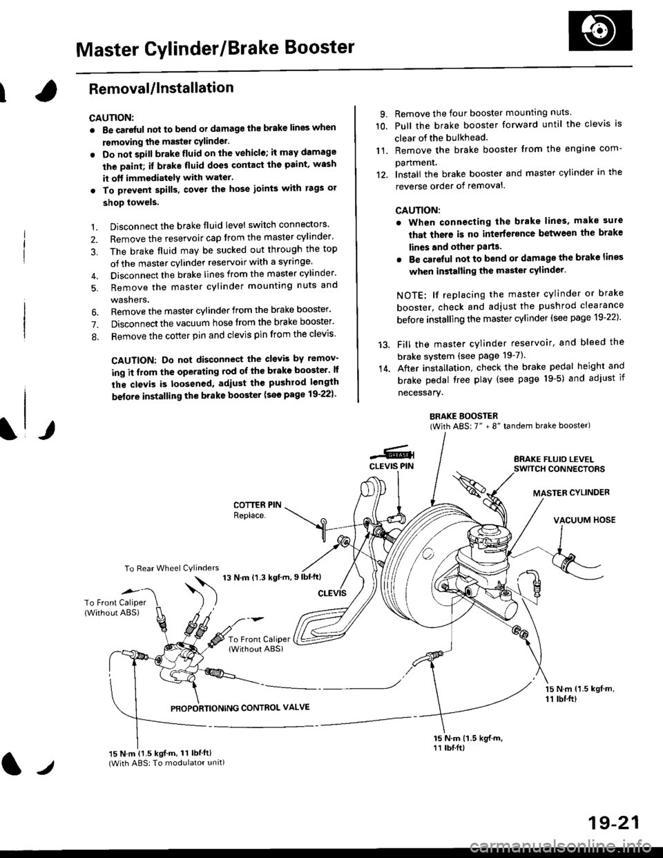
. Be care{ul nol to bend or damage the brake lines when
rsmoving the mastsr cYlinder.
. Do not soill brakefluid on the vehicle; it may damage
the paint; if brake fluid does contact the paint, wssh
it off immediatelY with water'
. To prevent spill3, cover the hose ioints with rags or
shop towels.
9. Remove the four booster mountlng nuts
10. Pull the brake booster forward until the clevis is
clear of the bulkhead.
11. Remove the brake booster from the engine com-
panmenr.'12. Install the brake booster and master cylinder in the
reverse order of removal.
CAUTION:
. When connecting the brake lines. make sure
that there is no inte erence between the brake
lines and oth6r Parts.
r Be careful not to bend or damage the brake lines
when installing the master cylinder.
NOTE: lf replacing the master cylinder or brake
booster, check and adiust the pushrod clearance
be{ore installing the master cylinder (see page 19-221'
Fill the master cylinder reservoir, and bleed the
brake svstem (see Page 19-7).
After installation. check the brake pedal height and
brake pedal tree play (see page l9-5) and adjust if
necessary.
BRAKE BOOSTER(With ABS: 7" + 8" tandem brake booster)
BRAKE FLUIO LEVELSWITCH CONNECTORS
MASTER CYLINDER
VACUUM HOSE
1.
2.
3,
5.
Disconnect the brake fluid level switch connectors'
Remove the reservoir cap from the master cylinder'
The brake fluid may be sucked out through the top
of the master cylinder reservoir with a syrlnge.
Disconnect the brake lines from the master cylinder'
Remove the master cylinder mounting nuts and
washers.
\l/
6. Remove the master cylinder from the brake booster'
7. Disconnect the vacuum hose trom the brake booster'
8. Remove the cotter pin and clevis pin from the clevis'
CAUTION: Do not disconnect the clevb by remov-
ing it from the operating rod of the brako booster' lf
the clevis is loosened, adiust the pushrod length
before installing th€ brake booster (see page 19-221'
COTTER PINReplace.
To Rear Wheel Cylinders
14.
-6.4CLEVIS PIN
To Front Caliper(Without ABS)$
t'N't'ttrnt'-''
To Front CaliperlWithout ABSi
PBOPORTIONING CONTROL VALVE
15 N.m {1.5 kgl m,11 tbtft)
15 N.m {1.5 kgif.m, 11 lbtft}(With ABS: To modulator unit)lr
19-21