1996 HONDA CIVIC Head unit
[x] Cancel search: Head unitPage 1819 of 2189
How To Use This Manual
Circuit Schematics
oa
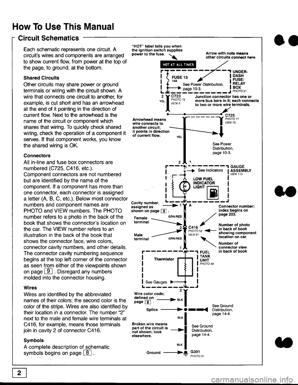
Each schematic represents one circult. A
circuit's wires and components are arranged
to show current flow, from power at the top of
the page, to ground, at the bottom.
Shared Circuits
Other circuits may share power or ground
terminals or wiring with the circuit shown. A
wire that connects one circuit to another, for
example, is cut short and has an arrowhead
at the end of it pointing in the direction of
current flow. Nelit to the anowhead is the
name o{ the circuil or comoonent which
shares that wiring. To quickly check shared
wiring, check the operation of a component it
serves. lf that component works, you know
the shared wiring is OK.
Connectors
All in-line and fuse box connectors are
numbered (C725, C416, etc.).
Component connectors are not numbered
but are identiJied by the name of the
component. lf a componenl has more than
one connector, each connector is assigned
a letter (A, B, C, etc.). Below most connector
numbers and comDonent names are
PHOTO and VIEW numbers. The PHOTO
number refers to a Dhoto in the back of the
book that shows lhe conneclor's location on
the car. The VIEW number refers to an
illustration in the back of the book that
shows the connector face, wire colors,
connector cavity numbers, and other details.
The connector cavity numbering sequence
begins at the top left corner oJ the connector
as seen from either of the viewooints shown
on page ffl . Disregard any numbers
molded into the connector housino.
Wires
Wires are identilied by the abbreviated
names of their colors; the second color rs the
color of the stripe. Wires are also identified by
their location in a connector. The number '2"
next to the male and female wire terminals at
C416, for example, means those terminals
join in cavity 2 of connector C416.
Symbols
A complete description of schematic
symbols begins on page | 8
"HOT" label tells you whenthe ignition switch suppliespower to the fuse. \
Artowhead meanswire connects toanother circuit;
Arrow with note rErngother circuils conncct h€re.
it .a
llu":: ^,{ ii t See Power Distribution, .I t----t oaqe tO-3. IL*--:--------J2 Y C723 Junction connectorYEL I Pao'o'8 more bus bars in it;
I - " " to two or more wire
l,/
-t>?
See PowerDistribution,page 10-3.
UNDER.DASHFUSE/RELAYBOX
has one oleach connactgterminala.
it ooints in directionof current flow.
TheImletor
t_I
Cavity number; L ---
Jiili'iJi!--' -----> '
shoin on page S .
Maleterminal
L?*?l?,-
"'"'I
c725
vlEUt/ 75
Connector number;index begins onpage 203.
Number ot photoin back ol bookshowing componentlocation on cat.
Number ofconneclor viewin back of book
7
GBN/FEO
See Ground
Soe Indicators I ASSEMBLY
:-------J
LOW FUELINDICATOFLIGHT r-l
EI
A
"o'r"/PHOTO 52 <-
\
FUELTANKUNIT
Splice ---------) O rr
".* I Page 14'4'
IBroken wire means | --^ -
iar";J.'It,;,rJ;ii; -----i Bffi,Bili*l
elsewhere. I 0a0e tn-a
IBrK Icround --->lL c301: ptioro 21
Page 1835 of 2189
Fuse
NumberAmpsPageFuse Name
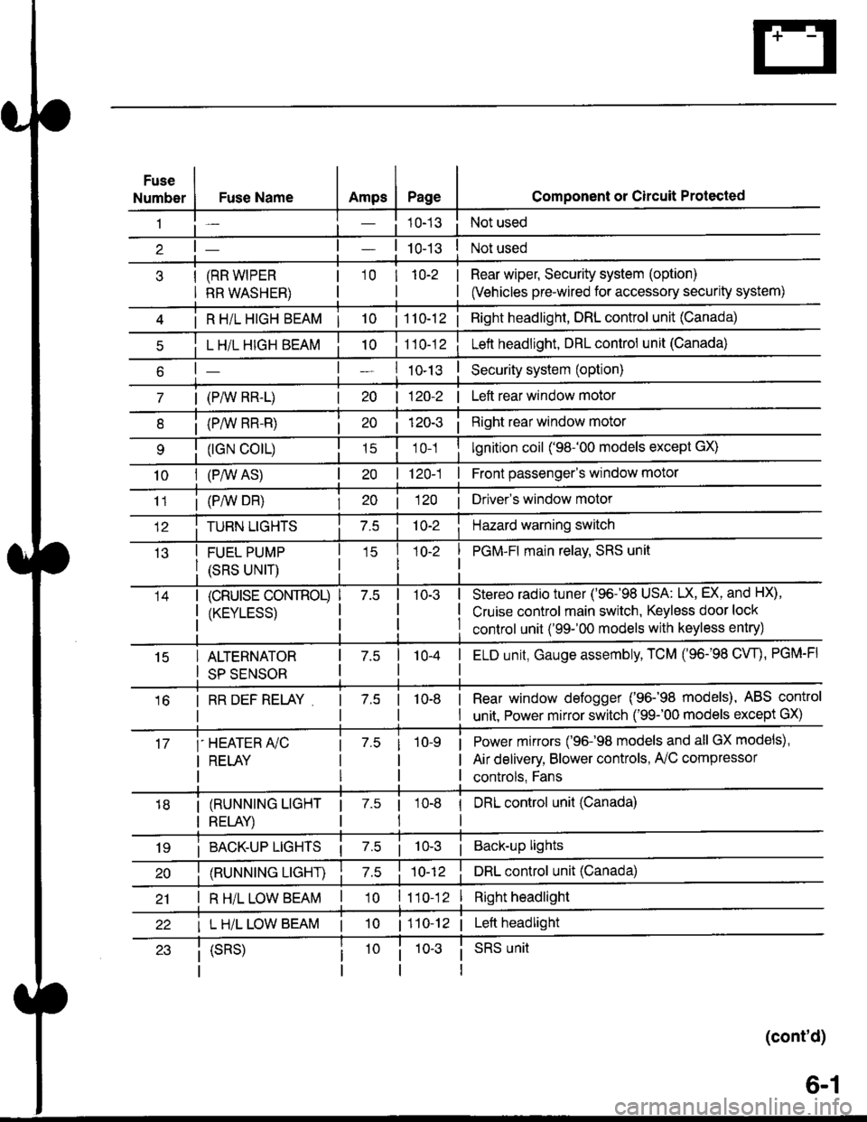
(RR WIPER
RR WASHER)
i R HiL HIGH BEAM | 10
L H/L HIGH BEAM
| (PAIV RR-L)
i (P/vv RR-R)
(rGN CO|L)
10I (P,^/V AS)
Component or Circuit Protected
Not used
Not used
Rear wiper, Security system (option)
(Vehicles pre-wired for accessory security system)
'10r 1n-2
I
| 1 10-12i Right headlight, DRL control unit (Canada)
Lett headlight, DRL control unit (Canada)
I ro-rsSecurity system (option)
| 120-2 | Left rear window motor
Right rear window motor
lgnition coil ('98-'00 models except GX)
| 120-1 | Front passenger's window motor
i (PiW DH)| 20 1 12O I Driver's window motor
TURN LIGHTSHazard warning switch
FUEL PUMP
(SRS UNIT)
PGM-FI main relav, SRS unit
(cRUrsE CoNTROL)
/KtrVt trSS\
Stereo radio tuner ('96-'98 USA: LX, EX, and HX),
Cruise control main switch, Keyless door lock
control unit ('99-'00 models with keyless entry)
15ALTERNATOR
SP SENSOR
l-a10-4I ELD unit, Gauge assembly, TCM (96-'98 CW, PGM-FI
16I RR DEF RELAY7.510-8I Rear window defogger ('96-'98 models), ABS control
I unit. Power mirror switch ('99-'00 models except GX)
i-HEATER r/C
I RELAY
Power mirrors ('96-98 models and all GX models),
Air delivery, Blower controls, AilC compressor
controls, Fans
I (RUNNING LIGHT
I RELAY)
1 7.5 1
tl
I DRL control unit (Canada)
i BACK-UP LTGHTSi Back-up lights
(RUNNING LIGHT)DRL control unit (Canada)
I R H/L LOW BEAM'10 l11o-12Right headlight
I L H/L LOW BEAM | 101110-12 | Left headlight
(cont'd)
(SRS)SRS unit
6-1
Page 1839 of 2189
Fuse
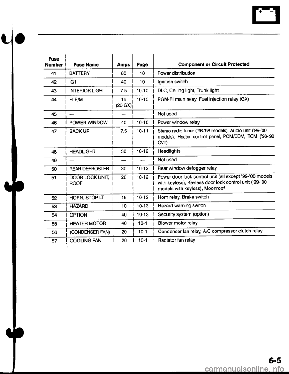
NumberFuse NameAmpsPage
BATTERY
Component or Circult Protected
Power distribution
lgnition switch
INTERIOR LIGHT | 7.5 | 10-10 | DLC, Ceiling light, Trunk light
FI E/M15 i(20 GX) i
i PGM-FI main relay, Fuel injection relay (GX)
Not used
POWER WINDOW| 10-10 | Power window relay
BACK UPStereo radio iuner ('9G'98 mod€ls), Audio unit ('99100
models), Heater control panel, PCM/ECM, TCM (9e'98
cvr)
HEADLIGHT
REAR DEFROSTER I
DOOR LOCK UNIT,
ROOF
i 10-12i Headlights
Not used
Rear window defogger relay
Power door lock control unit (all except '99-'00 models
with keyless), Keyless door lock control unit ('99-'00
models with keyless), Moonroof
i HORN, SrOP Lri 10-13i Horn relay, Brake switch
HAZARDHazard warning switch
OPTIONI 10-13I Security system (option)
i HEATER MOTOR Ii 10-1 i Blower motor relay
(CONDENSER FAN)
COOLING FANl1o-1
Condenser Jan relay, A'lC compressor clutch relay
Radiator tan relay
&5
Page 1840 of 2189

Ground-to-Components I ndex
f.,lONOTE: All ground wires are BLK unless otherwise noted.
GroundPageComponents or Circuit Grounded
Battery (BLKYEL)
Steering pump bracket
t+-rg ITransmission housing
l
G101
(-1)
G101
(-2)
14-2
and
14-3
ano
14-1
Powertrain or engine control module (PG1 and pG2 are BLK: LG1 and LG2 are
BRN/BLK), EGR control solenoid valve (CW, EGR valve and lift sensor (Dt6yS enginewith M,/T), Engine coolant temperature switch, pGM-Fl main relay, power steeringpressure switch (USA), Primary HO2S (D16Y5 engine with l\/,/T), Vehicle speed sensor,VTEC pressure switch (D16Y5/D16Y8 engines), CKF sensor (BRN/BLK), Transmission
control module (CYf) (Pc1 is BLK: LG1 is BRN/BLK)
Shielding betvveen the PCM or ECM and these components (all have BRN/BLK wires):
CKF sensor, TDC/CKP/CYP sensor. Primary and secondary heated oxygen sensors.
Knock sensor (CWDl6YB engine), Mainshaft speed sensor (AiT except CVT),
I Countershaft speed sensor (A/T except CVf)
Shielding between the TCM and these components (CVT) (all have BRN/BLK wires):
Drive pulley speed sensor, Driven pulley speed sensor, Secondary gear shaft
speed sensor
Powertrain or engine control module (PG1 and pG2 are BLK; LG1 and LGz are
BRN/BLK), EGR control solenoid valve (D16Y5 engine), EGR valve (Dt685), Engine
coolant temperature switch, Fuel pressure regulator shut-off solenoid valve (D1685),
PGM-FI main relay, Power steering pressure switch (USA), Vehicle speed sensor, VTECpressure switch (All except D16Y7 engine), CKF sensor (A
except 81642) (BRN/BLK)
Shielding between the PCM or ECM and these components (all have BRN/BLK wires):
CKF sensor, TDC/CKP/CYP sensor, Primary and secondary heated oxygen sensors,
Knock sensor (All except D16Y7 engine), i/ainshaft speed sensor (Arf except CW),
Countershaft speed sensor (A,/T except CVf), Drive pulley speed sensor (CW), Drivenpulley speed sensor (CVT), Secondary gear shaft speed sensor (CVf)
I Badiator fan motor, Right front parking/turn signat tight, Right headtight
G20214-4I Cruise control actuator, Left front parking/turn signal lights, Left headlight, Rear window
I washer motor, Windshield washer motor, Washer fluid level switch (,99-'00 Canada)
G401| +-o
and
14-7
Accessory power socket, Brake fluid level switch, Clutch interlock switch (M/T), Clutchswitch (lillT with cruise/D16Y5 engine with MfD, Combination wiper switch (Z wires),
Cruise control main switch, Cruise control unit, Dash lights brightness controller, Data
link connector, Daytime running lights control unit (Canada), Gauge assembly, Horn('96-'97 models), Integrated control unit, Interlock control unit (ArI), Keyless door lock
control unit ('99-'00 models with keyless), Moonroof close and open relays, Moonroof
switch, Park pin switch (A/r), Power window relay, Rear window defogger relay, Rear
window defogger switch ('96-'98 models), Steering lock, Stereo radio tuner (,96-,98
USA: LX, EX, and HX), Turn signal/hazard relay, Windshield wiper motor.....plus
everything grounded through G402
6-6
Page 1966 of 2189
See Wiper,ryVasher
@
FUSE 30l|lslFl,|tEl{luotfT3
UNDER-DASHFUSE/RELAYBOX
I
t
I
I
I
.1 1
-t
\
\\
Sea PowerDistfibution,pag€ 10-5. iz
FUSE 15ALTEi}IATORsP 8S$80n?.54
A8
7'5A soe Headtight sss Power- Switch, Distibution,page 100-t. pags 1G7. foINTEGRATEDCONTNOLUNIT
vEw af
\
\
\
t
I
,
I
I
I
a-------
FUSE 26FR \I/IP€gFi WASTIEF204
Ught8.ONnemhderCircrti
lfllsnl|literWip6r RelayCircuit
Combin€dl,Ylper/WarhotCireuit
*I "'�r
II
II
-----[---t-----
""r,".* I ".u-"r l
tt\--
See WiperMasher
70-1
Page 2006 of 2189
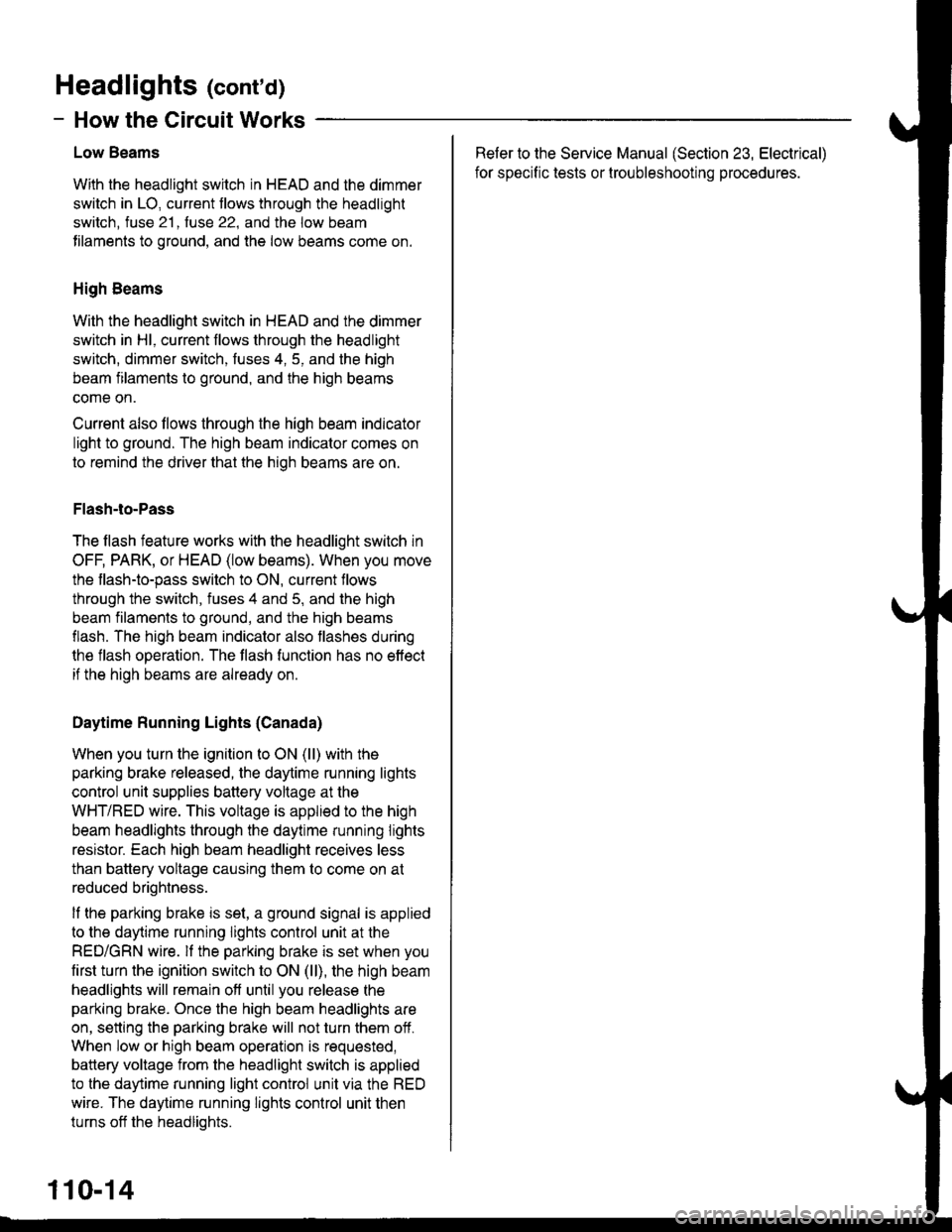
Headlights (cont'd)
- How the Circuit Works
Low Beams
With the headlight switch in HEAD and the dimmer
switch in LO, current tlows through the headlight
switch. fuse 21 . fuse 22. and the low beam
tilaments to ground, and the low beams come on.
High Beams
With the headlight switch in HEAD and the dimmer
switch in Hl, current flows through the headlight
switch, dimmer switch, fuses 4, 5, and the high
beam filaments to ground, and the high beams
come on.
Current also llows through the high beam indicator
light to ground. The high beam indicator comes on
to remind the driver that the high beams are on.
Flash-to-Pass
The flash feature works with the headlight switch in
OFF, PARK, or HEAD (low beams). When you move
the flash-to-pass switch to ON, current flows
through the switch, fuses 4 and 5, and the high
beam filaments to ground, and the high beams
flash. The high beam indicator also flashes during
the flash operation. The flash function has no effect
if the high beams are already on
Daytime Running Lights (Canada)
When you turn the ignition to ON (ll) with the
parking brake released, the daytime running lights
control unit supplies battery voltage at the
WHT/RED wire. This voltage is applied to the high
beam headlights through the daytime running lights
resistor. Each high beam headlight receives less
than battery voltage causing them to come on at
reduced brightness.
lf the parking brake is set, a ground signal is applied
to the daytime running lights control unit at the
RED/GRN wire. lf the parking brake is set when you
first turn the ignition switch to ON (ll), the high beam
headlights will remain off until you release the
parking brake. Once the high beam headlights are
on, setting the parking brake will not turn them ofi.
When low or high beam operation is requested,
battery voltage from the headlight switch is applied
to the daytime running light control unit via the RED
wire. The daytime running lights control unit then
turns off the headlights.
Refer to the Service Manual (Section 23, Electrical)
for specific tests or lroubleshootrng procedures.
110-14
Page 2038 of 2189
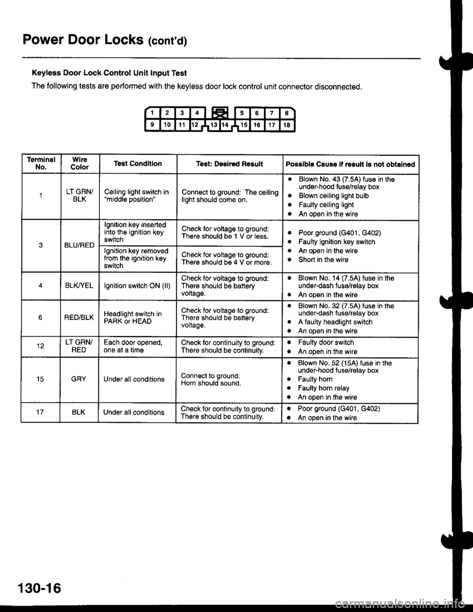
Power Door Locks (cont'd)
Keyless Door Lock Control Unit Input Test
The following tests are performed with the keyless door lock control unit connector disconnected.
TerminalNo.WireColorTest ConditionTest: Desir€d ResultPossible Cause if result ls not obtain€d
1LT GRN/BLKCeiling light switch in"middle position"Connect to ground: The ceilinglight should come on.
aBlown No. 43 (7.5A) luse in theunder-hood tuse/relay box
Blown ceiling light bulb
Faulty ceiling light
An open in the wire
o
a
a
3BLU/RED
lgnition key insertedinto the ignition keyswitch
Ch€ck lor voltage to ground:There should be I V or less.aPoor ground (G401, G402)
Faulty ignition key switch
An open in the wire
Short in the wire
a
a
o
lgnition key removedlrom the ignition keyswitch
Check for voltage to ground:There should be 4 V or more.
BLfiEtlgnition switch ON (ll)Check lor voltage to ground:
There should be batteryvoltage.
. Blown No. 14 (7.54) fuse in theunder-dash fuse/relay box
. An open in the wire
bREO/BLKHeadlight switch inPARK OT HEAD
Check for voltage to ground:
There should be batteryvoltage.
aBlown No. 32 (7.5A) luse in theunder-dash fuse/relay box
A faulty headlight switch
An open in the wire
a
o
LT GRN/RED
Each door opened,one at a timeCheck lor continuity to ground:
There should be continuitv.
oFaulty door switch
An open in the wireo
15GRYUnder all conditionsConnect to ground:
Horn should sound.
. Blown No. 52 (154) fuse in theunder-hood fuse/relay box
. Faulty horn
. Faulty horn relay
o An open in the wire
BLKUnder all conditionsCheck lor continuity to ground:
There should be continuity.
aPoor ground (G401 , G402)
An open in the wirea
130-16
Page 2043 of 2189
';;;1; I r1-- --'I UNDE'------J-i i I 11'.1'.11 lSBi'"Driver .r ' HEADIIOriT '::
door !:t { t-- lPHo'o7unlock Unlock Lock | : L j,- -- -Jinpd input lpr,_j : -9lT1u.r^ -
---- Canada ---'------l
POWER DOOR LOCK ;CONTROL UNIT ,
k;i
L______jg:_l=,_______ juj_.r, _r_f 9_.-u:'F":;!-_ --",*tI
i !**""""I
*",*"[T*Fi
i
.",1
o*u*u'
,* -".11 t-J--'-----'-hff I
"ll-_-_il
|semooeriir f,
't
tr
18 f ia-eii,
L______d"t";tlo"n,o"n| """*",|ft"t'i fsEcuRrwLED,, L--J---------J",0. | | -liffi*
,i,Hfil _[l!,ffisHdsh
i ,of.--s L--d,---t--------cl-+-'dl "."""" !-------t - I, t - Drivgr's door Unlock Lock I Light I U
ii -F-o-:y-"1 - -:i"-1i3y. -TTi- - - - - :"ll'i - - ; 13'*" i q._"u_n'r !--1---- ---'l99,trRoL I
: \varst :l;#"b" I; ; $vitch Securiiv Bus Remote Bus Bus i I vttwte ll C422, f inqrt outDut d€,.az LED control data 0 data l , : I P1oTo 58-a- --' s Y---^a---.;f --.;Y---^;Y---:Y - - - - r ;-.tr'---
. ; UNIT
i *t Drtusr's door untock Lock i ugnt it - uavgrs ooor untocx LocK I Lrgn'
: LED control unloc* outpul outrut outpul ' flash- ': ' iontrot I sEcuRlw
--1-"' ---' I coNrRoL' 'i uNlri vatst, I VarEr tl PHQ|AT3: ; s,vitch Securiiy Bus Remote Bus Bus t)vtEwte, f inarr ornout d'de2 LED control data 0 data l� :
7-1 e4re4lon
lfil Iffi;*l
[I$'':r*il
: 84 |, 85A 87A 811 |' Bt2 |' 813 |' vtEw68 | ! sae r.teadli
i i'=::t:::ti------r------s------r, -"** i : ! 8yJfu;; I I Vabt S€curity 8us Remot€ Bus Bus I Reieiver ! ; --_ _.._ ll
:i iffi$ input data2 ffiDul
datao datal iunrr !:""'"^l
(cont'd)
133-1