1996 HONDA CIVIC reverse sensor
[x] Cancel search: reverse sensorPage 857 of 2189
17.
18.
19.
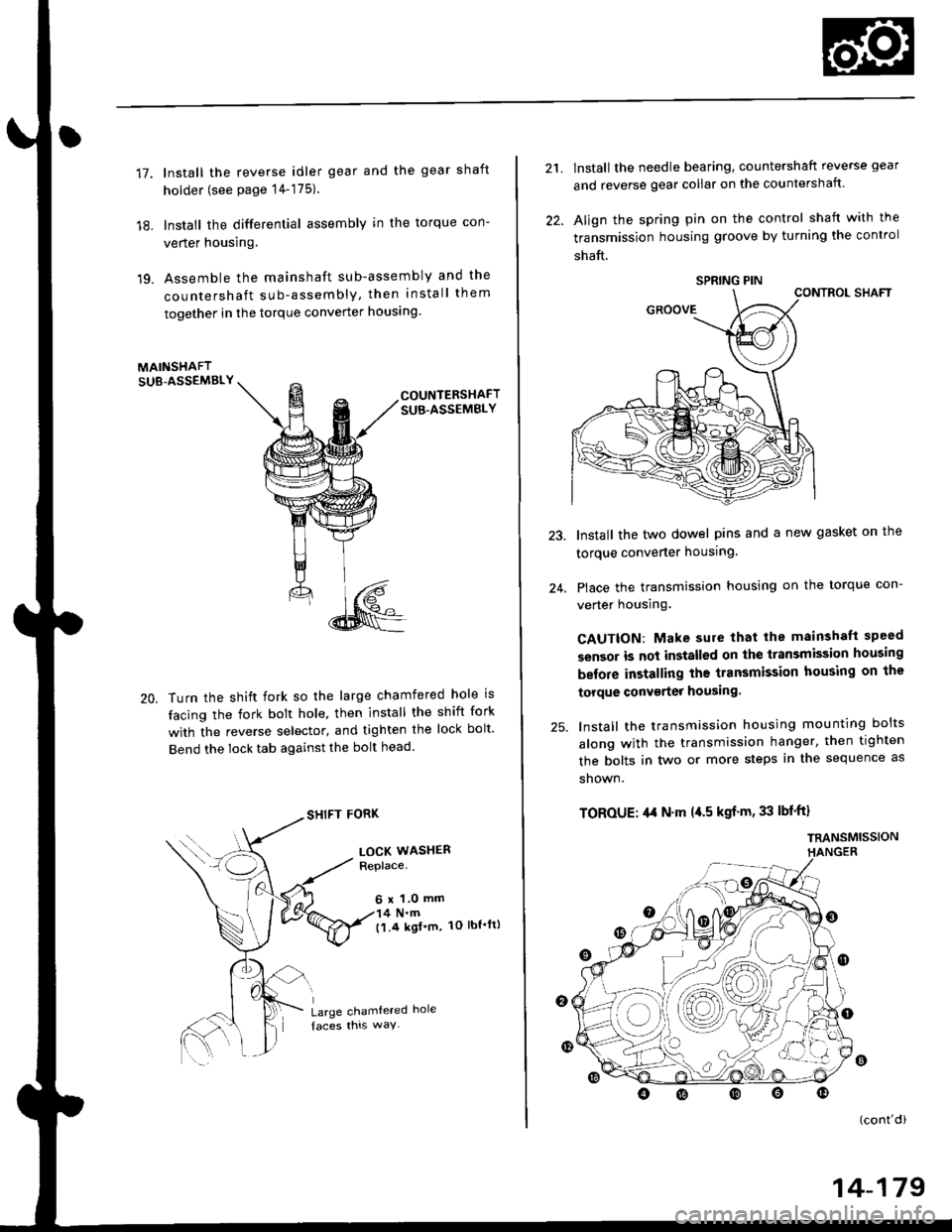
lnstall the reverse idler gear and the gear shaft
holder (see page 14-175).
lnstall the differential assembly in the torque con-
verter housing.
Assemble the mainshaft sub-assembly and the
countershaft sub-assembly, then install them
together in the torque converter houslng
MAINSHAFTSUB-ASSEMBLY
20,
COUNTERSHAFTSUB.ASSEMBLY
Turn the shift fork so the large chamfered hole is
tacing the fork bolt hole, then install the shift fork
with the reverse selector, and tighten the lock bolt'
Bend the lock tab against the bolt head
SHIFT FORK
LOCK WASHERReplace.
6 x 1.0 mm4 N.m('l.4 kgl'm, 1O lbt'ft)
Large chamtered hole
21.
22.
lnstall the needle bearing, countershaft reverse gear
and reverse gear collar on the countershaft.
Align the spring pin on the control shaft with the
transmission housing groove by turning the control
shaft.
CONTROL SHAFT
Install the two dowel pins and a new gasket on the
torque converter housing.
Place the transmission housing on the torque con-
verter housing.
CAUTION: Make sure that lhe mainshaft speed
sensor is not installed on the transmission housing
before installing the transmission housing on the
torque conv€rter housing.
lnstall the transmission housing mounting bolts
along with the transmission hanger, then tighten
the bolts in two or more steps in the sequence as
shown.
TOROUE: ,l,t N'm l{.5 kgf'm, 33 lbf'ft}
TRANSMISSIONHANGER
24.
o
(cont'di
SPRING PIN
14-179
Page 871 of 2189

Continuously Variable Transmission (CVTI
Special Tools ................ 14-194
Description .................... 14-195
Clutches/Reverse Brake/Planetary
Gear/Pulleys .......... 14-198
power Flow ..............,..... 14-200
Electronic Control SYstem(,96 - 98 Modets) ......14-203
Electronic Control System
('99 - oo Models) " 14-205
Hydraulic Control '....... 14-208
Hydraulic Flow .'..-.....'... '14-212
Park Mechanism .....-...'.' 14-222
Eleqtrical Systom
Component Locations'96 - 98 Models """"""' 14-224,99 - 00 Modets ............. 14-225
TCM Circuit Diagram ('96 - 98 Models) ............. 14-226
TCM Terminal Voltage/Measuring Condiiions ('96 - 98 Models) '.... 14-228
PcM Circuit Oiaqram{A/T Control System: '99 - 00 Models} ...--.... 14-230
PCM Terminal Voltage/Measuring Conditions('99 - 00 Models)
A/4 Control System .'.'...14-232
Troubleshooting Procedures ... . .... .....',........."' '14-234
Symptom-to-ComPonent Chart
Electrical System - '96 - 98 Models ......'..... '14-234
Electrical System -'99 - 00 Models ..'....-..-. '11-210
Electrical Troubleshooting
Troubleshooting Flowcharts('96 - 98 Models) """'11-242
Troubleshooting Flowchart
('99 - 0O Modets) ...... 14-265
Linear Solenoids/lnhibitor Solenoid
Test ......................... . ...... 14-29f
Drive Pulley/Driven Pulley/Secondary Gear
Shaft Speed Sensors
Replacement .........'...... .14-292
Start Clutch Control
Start Clutch Calibration Procedure ....... ....,. 14-293
Hydraulic SYstem
Symptom-to-ComPonent Chart
Hydraulic System '.'.......14-294
Road Test ............................ 14-296
Stall Speed
Test......................... ...... 14-294
Fluid Level
Checking/Changing ....... 14-299
Pressure Testing ................. 14-300
Lower Valve BodY AssemblY
Replacement ..........,... 14-302
ATF Filter
Removal/lnstallation ..... 14-303
Transmission
Transmission
Removal ........... . 14-304
lllustrated Index
Transmission/Lower Valve BodY
Assembly ................. 14-308
Transmission Housing/Flywheel Housing ... 14-310
End Cover/f ntermediate Housing ..........'.'.... 14-312
Transmission Housing/Lower Valve Body Assembly
Removal ..........'.... .. " 14-314
Transmission Housing/Flywhesl Housing
Removal ................. ........ 1+316
End Cover/lntermediate Housing
14-318Removal .........,...............
Manual Valve Body
Disassembly/lnspection/Reassemblv .'.'.'..... 1 4-320
Forward Clutch
lltustrated Index ........................................ 14-321
Disassemblv .................. 14-322
Reassemblv , ,, . ',','......14-324
Secondary Gear Shaft
25 x 35 mm Thrust Shim Selection ..'.'....-... 14-324
Differential
lllustrated lndex ...,.....................,.,...-.-.-...'... 14-329
Backlash Inspection .-....14-329
Bearing Replacement ......'........'....'... ....'... 14-330
Differential Carrier Replacement ........'........ 14-330
Oil Seal Removal ........... 14-331
Oil Seal Installation/Side Clearance ....... . . 14-331
Flywheel Housing Input Shaft Oil Seal
Replacement .....,.... ...'.'.. 14-333
Transmission Housing Bearings
Driven Pulley Shaft Bearing
Replacenient ...................'. . ...................'.. 14-334
Secondary Gear Shaft Bearing
Reolacbment ...................... . .......... . ........ 14-335
Flywheel Housing Beating
Secondary Gear Shaft BearingReo1acement..................,........................... 14-335
Ring Gear Bearing
Replacement......... ........ 14-336
Control Shaft Assembly
Removal/lnstallation ....................'........... 14-336
Transmission
Reassembly .................. 14-338
Flywheel/Drive Plate .. . ...... . ...... ... . ....-.....'.'...14-341
Transmission
lnstalation ..................... 14-348
Cooler Flushing .'......... 14-352
shift cable
Removal/lnstallation....'........." """ 14-354
Adjustment .......'........ 14-355
Shift Lever ........................,. 14'356
Shift Indicator Panel
Adjustment ................ 14-357
ATF Cooler/Hoses
lnsta llation ......,,...... .... 14-357
Page 873 of 2189

Description
The Continuously Variable Transmission (CVT) is an electronically controlled automatic transmission with drive and driv
en Oullevs, and a steel belt. The CVT provides non stage speeds forward and one reverse. The entire unit is positioned in
line with the engine.
Transmission
Around the outside of the flywheel is a ring gear which meshes with the starter pinion when the engine is being staned.
The transmission has four parallel shafts: the input shaft, the drive pulley shaft. the driven pulley shaft, and the secondary
gear shaft. The input shaft is in line with the engine crankshaft. The drive pulley shaft and the driven pulley shaft consist of
movable and fixed face pulleys. Both pulleys are linked by the steel belt.
The input shaft includes the sun gear. The drive pulley shaft includes the forward clutch which mounts the carrier assem-
bly on the forward clutch drum. The carrier assembly includes the pinion gears which mesh with the sun gear and the ring
gear. The ring gear has a hub-mounted reverse brake disc.
The driven pulley shaft includes the start clutch and the secondary drive gear which is integral with the park gear' The sec-
ondary gear shaft is positioned between the secondary drive gear and the final driven gear. The secondary gear shaft
includes the secondary driven gear which serves to change the rotation direction. because the drive pulley shaft and the
driven oullev shaft rotate the same direction. When certain combinations of planetary gears in the transmission are
engaged by the clutches and the reverse brake, power is transmitted from the drive pulley shaft to the driven pulley shaft
to provide E, E, E, and El.
Electronic Control'96 - 98 Models:
The electronic control system consists of the Transmission Control Module (TCM), sensors, three linear solenoids, and a
inhibitor solenoid. Shifting is electronically controlled under all conditions'
The TCM is located below the dashboard, behind the kick panel on the driver's side.'99 - 00 Models:
The electronic control svstem consists of a Powertrain Control Module (PCM), sensors, three linear solenoids and an
inhibitor solenoid. Shifting is electronically controlled under all conditions. A Grade Logic Control System to control shift-
ing in E position while the vehicle is ascending or descending a slope.
The PCM is located below the dashboard, under the kick panel on the passenger's side.
Hydraulic Control
The lower valve body assembly includes the main valve body, the Pressure Low (PL) reguiator valve body, the shift valve
body, the start clutch control valve body, and the secondary valve body. They are positioned on the lower part of the
transmission housing.
The main valve body contains the Pressure High (PH) control valve, the lubrication valve, and the pitot regulator valve.
The secondary valve body contains the PH regulator valve, the clutch reducing valve, the start clutch valve accumulator,
and the shift inhibitor valve. The PL regulator valve body contains the PL regulator valve and the PH-PL control valve
which is ioined to the PH,PL control linear solenoid. The inhibitor solenoid valve is bolted on the PL regulator valve body.
The shift valve body contains the shift valve and the shift control valve. which is joined to the shift control linear solenoid.
The start clutch control valve body contains the start clutch control valve, which is joined to the start clutch control linear
solenoid. The linear solenoids and the inhibitor solenoid are controlled by the TCM or PCM. The manual valve body which
contains the manual valve and the reverse inhibitor valve, is bolted on the intermediate housing.
The ATF pump assembly is located on the transmission housing, and is linked with the input shaft by the sprockets and
the sprocket chain. The pulleys and the clutch receive fluid from their respective feed pipes, and the reverse brake receives
fluid from internal hydraulic circuit.
Shift Control Mechanism
Input from various sensors located throughout the vehicle determines which linear solenoid the TCM or PCM will activate.
Activating the shift control linear solenoid changes the shift control valve pressure, causing the shift valve to move. This
pressurizes the drive pulley pressure to the drive pulley and the driven pulley pressure to the driven pulley and changes
their effective pulley ratio. Activating the start clutch control linear solenoid moves the start clutch control valve. The start
clutch control valve uncovers the port, providing pressure to the start clutch to engage it(cont'd)
14-195
,!
Page 972 of 2189
t.
rl,
fl,
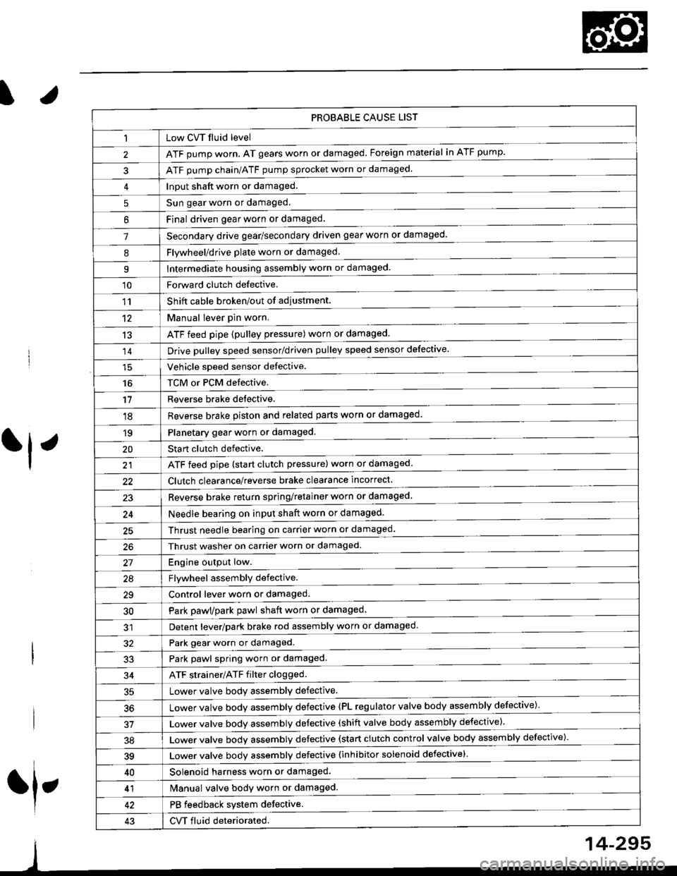
PROBABLE CAUSE LIST
Low CVT fluid level
ATF pump worn. AT gears worn or damaged. Foreign material in ATF pump.
ATF pump chain/ATF pump sprocket worn or damaged.
Input shaft worn or damaged.
Sun gear worn or damaged.
Final driven oear worn or damaqed,
Secondary drive gear/secondary driven gear worn or damaged-
5
6
1
8Flywheel/drive plate worn or damaged.
Intermediate housing assembly worn or damaged.9
'10Forward clutch defective.
Shift cable broken/out of adiustment.
M"nu"t t"uffi
ATF feed pipe (pulley pressure) worn or damaged.
Vchiclc speed sensor defective.
TCM or PCM defective.
Reverse brake detective.
1'�r
't2
13
14
16
'11
'18
1qPlanetary gear worn or damaged.
Sta rt clutch defective.
ATF feed pipe (start clutch pressure) worn or damaged
20
t't
Clutch clearance/reverse brake clearance incorrect.
23Reverse brake return spring/retainer worn or damaged
24Needle bearing on input shaft worn or damaged.
25Thrust needle bearing on carrier worn or damaged.
Thrust washer on carrier worn or damaged.
Enoine outout low.------------------------
Flvwhcel assemblv defective.
Control lever worn or damaged.
Park pawl/park pawl shaft worn or damaged
Detent lever/park brake rod assembly worn or damaged
27
29
30
32Park gear worn or damaged.
Park pawl spring worn or damaged.
ATF strainer/ATF filter clogged.
Lower valve body assembly defective.
Lower valve bodv assemblv defective (PL regulator valve body assembly defective)'
33
34
50
Lower valve bodv assembly defective (shift valve body assembly defective).
Lower valve bodv assemblv defective (start clutch control valve body assembly defective)'
39Lower valve bodv assemblv defective {inhibitor solenoid defective}
40Solenoid harness worn or damaged.
Manual valve body worn or damaged.
PB feedback system defective.
CVT fluid deteriorated.
41
43
14-295
Page 990 of 2189

6) TRANSMISSION HOUSING GASKET Replace'
@ DOWEL PIN
@) ATF FEED PIPE
@ o-RING Replace.
60 o-RING Replace.
@) DRIVE PULLEY SPEED SENSOR
@ TRANSMISSION HANGER
@ SNAP RING
@ txaust Sxtfu, zs t 31 mm selective part
@ SALL BEARING
6J RING GEAR6D SNAP RING
@ aevense aRlxe rND PLATE Selective part
@ REVERSE BRAKE DISC
@ REVERSE BRAKE PLATE
@ DISC SPRING6} THNUST WASHER
@} finusr NeeoLr eelnNc
@ THRUST WASHER
@ GARRIER ASSEMBLY
@ THRUST WASHER
@ THRUST NEEDLE BEARING
@} SUN GEAR
@ SEALING RING REPIACE'
@ NEEDLE BEARING
@ INPUT SHAFT
@ NEEDLE BEARING
@ SEALING RING FEPIACE'
@ SEALING RING {RUBBERI Replace'
@ ATF FEED PIPE
O END COVER
O ATF FEED PIPE
O DOWEL PIN
@ O-RING Replace.G) FEED PIPE FLANGE
@ reeo ppe ruruce puru
O] ROLLERO IruTENMEDNTE XOUSING ASSEMBLY
ao corutnoL sxlrr lsseugLv
@ tnlrusmtsstottt ttoustt'tc
@ SHIFT CABLE BRACKET
c) BREATHER CAP
@ oll- SEAL Replace.
@ CONTROL LEVER
G LoCK WASHER Replace.(D secololaY ceaR SHAFT SPEED sENsoR
o) onvel put-uv sPEED SENSOR
@ O-RING Replace.(O SNAP RING6 rnmrsutsstoru xouslNc oRlvEN PULLEY
SHAFT ROLLER BEARING
@ END COVER GASKET REPIACE'
@ o-RING Replace
6o mnruulL vnLVe goDY LINE A
64 MANUAL VALVE BODY LINE B
@ O-RING Replace.
@ DETENT SPRING
O ATF FEED PIPE
@ O-RING Replace.
@ MANUAL VALVE EODY
@ DOWEL PIN
@ r'rllull valve goDY SEPARAToR PLATE
6D SNAP RING
@t roRwlno cturcx ASSEMBLY
@ o-RING Replace
@ SNAP RINGo3 spnlruc aetlrupn/RETURN SPRING ASSEMBLY
@ nevense ennr eBtottt
@ o-RING Feplace.
@ SNAP RING RE'AINER
@ ATF FEED PIPE
.1,
TOROUE SPECIFICATIONS
6x1.0mm
6x1.0mm
8 x 1.25 mm
8 x 1.25 mm
8 x 1.25 mm
12 N.m (1.2 kgf'm,8.7 lbf'ft)
14 N.m {1.4 kgf'm, 10 lbift)
37 N.m (3.8 kgf'm, 27 lbf'ft)
26 N.m (2.7 kgf'm,20 lbf'ft)
29 N.m (3.0 kgf'm, 22 lbf'ft)
6B
8B
8F
8G
14-313
rl,
Page 1139 of 2189
I
NOTE: Wash the knuckle and hub thoroughly in
high flash point solvent before reassembly.
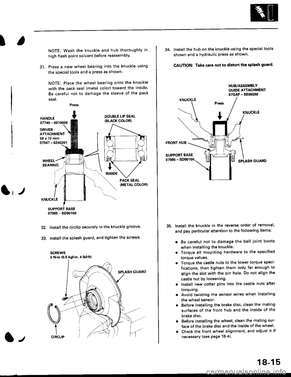
31. Press a new wheel bearing into the knuckle using
the specialtools and a press as shown
NOTE: Place the wheel bearing onto the knuckle
with the pack seal (metal color) toward the inside
Be careful not to damage the sleeve of the pack
seal.
Press
HANOI.E07749 - 001
DRIVERATTACHMENT58x72mm07947 - 6340201
DOUBLE LIP SEAL
{BLACK COLOR)
KNUCKLE
SUPPORT BASE07965 - SD90100
Installthe circlip securely in the knuckle groove'
Installthe splash guard, and tighten the screws.
scREws5 N.m (0.5 kgd m, 4lbt'ft)
32.
33.
l-,
18-15
34. lnstall the hub on the knuckle using the specialtools
shown and a hydraulic press as shown.
CAUTION: Take care not to distort tho splash gusrd'
HUB/ASSEMBLYGUIDE ATTACHMENT07GAF- SEflt2d)
KNUCKLE
FRONT HUB
SUPPORT BASE
07966 - StXx)100SPLASH GUARD
tnstall the knuckle in the reverse order of removal'
and pay particular attention to the following items:
. Be careful not to damage the ball joint boots
when installing the knuckle.
. Torque all mounting hardware to the specified
torque valugs.
. Torque the castls nuts to the low€r torque specl-
fications, then tighten them only far enough to
align the slot with the pin hole. Do not align the
castle nut by loosening.
. lnstall new cotter pins into the castle nuts after
torquing.
. Avoid twistin0 the sensor wires when installing
the wheel ssnsor.
. Before installing the brake disc, clean the mating
surfaces of the front hub and the inside of the
brake disc.
. Before installing the wheel, clean the mating sur-
face ofthe brake disc and the inside of the wheel
. Check the front wheel alignment, and adjust it if
necessary (see page 18-4).
Page 1140 of 2189
Front Suspension
L
Lower Ball Joint Replacement
Remove the knuckle (see page 18-11).
Remove the boot by prying the set ring off.
Check the boot for deterioration and damage.
replace if necessary.
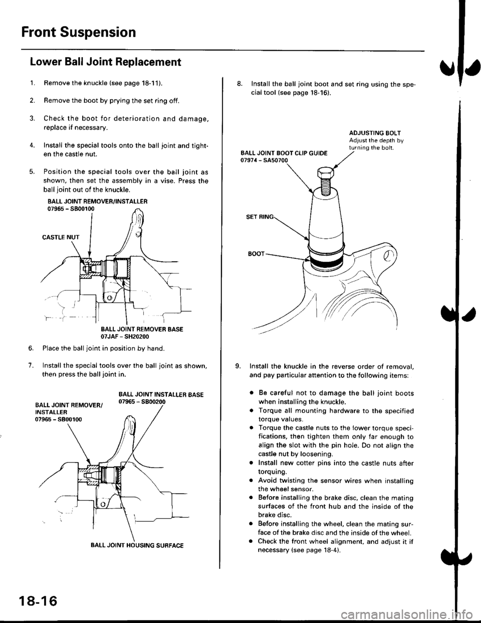
Install the special tools onto the ball joint and tight-
en the casfle nut.
Position the special tools over
shown. then set the assembly in
ball joint out of the knuckle,
BALL JOINT REMOVER/INSTALLER07965 - SB00r00
CASTLE NUT
the ball joint as
a vise. Press the
lf
7.
BALL JOINT REMOVER BASE07JAF - SH20200
Place the ball joint in position by hand.
Install the special tools over the ball joint as shown,
then press the ball joint in.
BALL JOINT INSTALLEB BASE07965 - 5800200
BALL JOINT HOUSING SURFACE
18-16
8. Install the ball joint boot and set ring using the spe-
cial tool (see page 18-16).
ADJUSTING BOLTAdjust rhe depth byturning the bolt.
Install the knuckle in the reverse order of removal,
and pay particular attention to the following items:
. Be careful not to damage the ball joint boots
when installing the knuckle,
. Torque all mounting hardware to the specified
torque values.
. Torque the castle nuts to the lower torque speci-
fications. then tighten them only far enough to
align the slot with the pin hole. Do not align the
castle nut by loosening.
. Install new cotter pins into the castle nuts after
torquang.
. Avoid twisting the sensor wires when installing
the wheel sensor.
. Before installing the brake disc. clean the mating
surfaces of the front hub and the inside of the
brake disc.
. Before installing the wheel, clean the mating sur-
face of the brake disc and the inside of the wheel.. Check the front wheel alignment, and adjust it if
necessary {see page 18-4).
Page 1229 of 2189
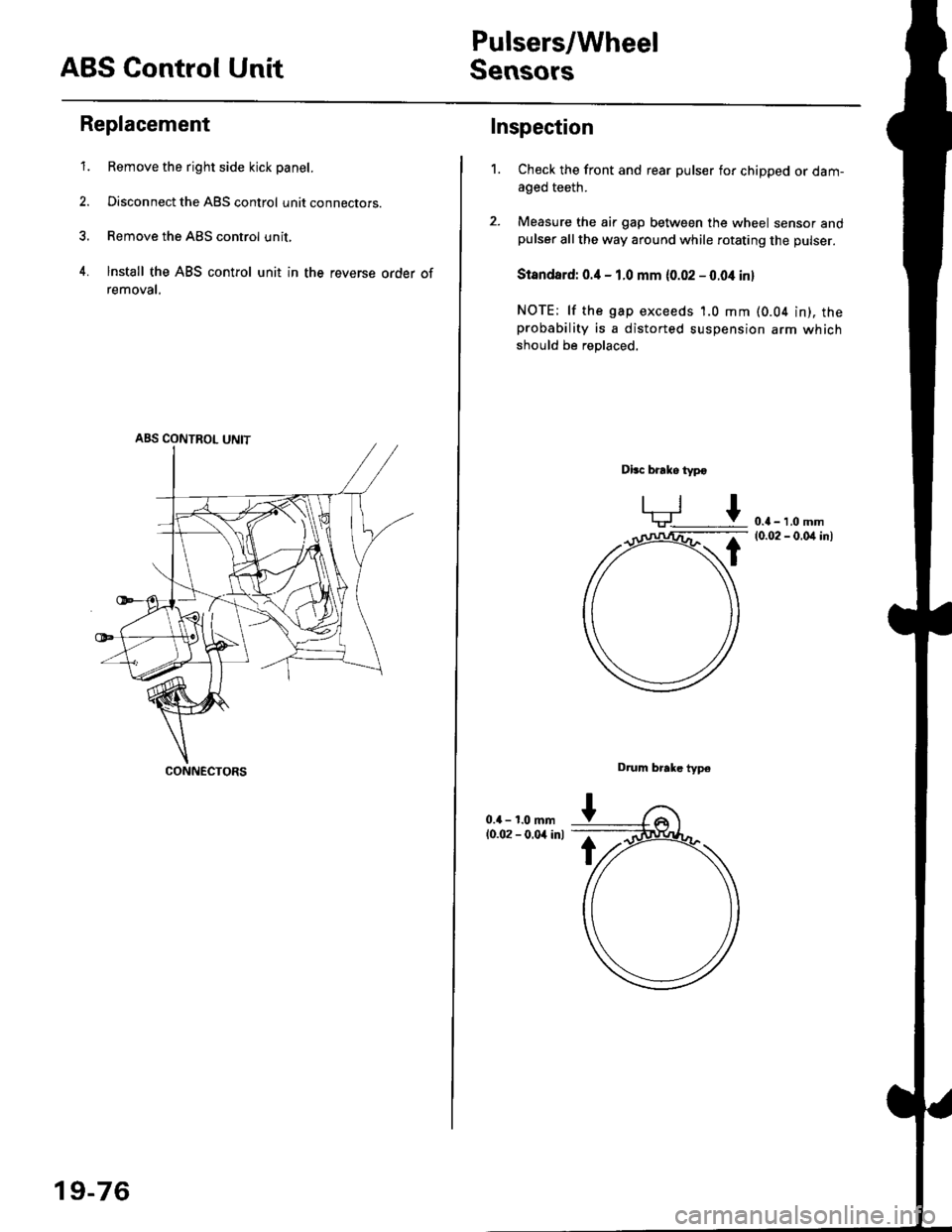
ABS Control Unit
Pulsers/Wheel
Sensors
Replacement
1. Remove the right side kick panel.
2. Disconnect the ABS control unit connecrors.
3. Remove the ABS control unit,
4. lnstall the ABS control unit in the reverse order of
removal,
CONNECTORS
19-76
Inspection
Check the front and rear pulser for chipped or dam-aged teeth.
Measure the air gap between the wheel sensor andpulser all the way around while rotating the pulser.
Slandard: 0.4 - 1.0 mm (0.02 - 0.04 in,
NOTE; lf the gap exceeds 1.0 mm (0.04 in), theprobability is a distorted suspension arm which
should be replaced.
Dbc brake typo
0.{ - 1.0 mm(0.02 - 0.04 in)
Drum brake typ6
1.