Page 1749 of 2189
)Disconnecting the Airbag Connector(sl
'1. Disconnect the negative battery cable, and wait at
least three minutes.
2. Disconnect the airbag connector(sl.
Driver's Side:
. Remove the access panel from the steering wheel'
then disconnect the driver's airbag 2P connector and
cable reel 2P connector.
!@@ To prevent sccidental 8irbag deployment, turn th€ ignition switch oFF. disconncct th€ negative battery
ffi, "nd *"it thr"e minutes b€fore disconnocting any sRS conn'ctors'
. Before disconnecting the SRS main harness (A) from the SRS unit' disconnect both airbags (C' D)'
.Beforedisconnectingthecab|ereel2Pconnector(B),disconnectthedriver,sairbag2Pconnector(c).
F ont PasEanga/3 Side:
. Remove the glove box. then disconnect the front pas-
senger's airbag 2P connector and SRS main harness
2P connector.t
FRONT PASSENGER'SAIRBAG2P CONNECTOR
CABTT REEL2?CONNECTOR
AOCESS PANEL
a,
24-11
Page 1807 of 2189
)
5, Reconnect the airbag connector(s)'
Front Passengor's Side:
a Attach the airbag connector to the connector holder'
then reinstallthe glove box.
FRONT PASSENGER'S AIRBAG
oo
24-69
Driver's Side:
a Connect the driver's airbag 2P connector to the cable
reel 2P connector, then install the acc€ss panel on the
steering wheel
DRIVER'S AIRBAG2P CONNECTOR
6. Connect the battery positive cable, then connect the
negative cable.
7. After installing the
operatlon:
. Turn the ignition
tor light should
and then go off
a Make sure both horn buttons work
airbag, confirm Proper sYstem
switch ON (ll); the SRS indica-
come on for about six seconds
Page 1808 of 2189

Airbag
Disposal
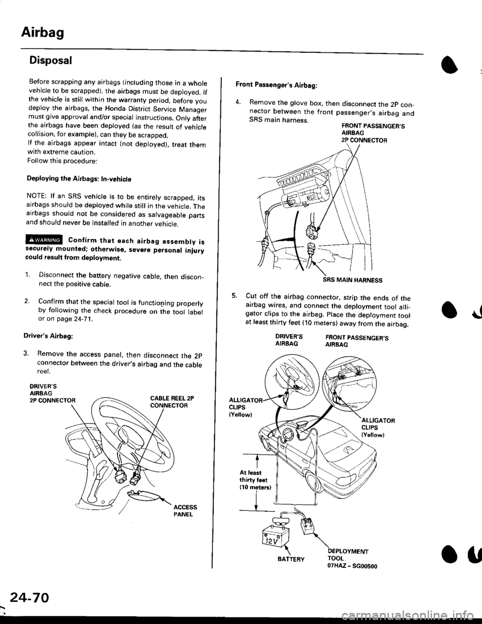
Before scrapping any airbags (including those in a wholevehicle to be scrapped), the airbags must be deployed. lfthe vehicle is still within the warranty period, before youdeploy the airbags, the Honda District Service Managermust give approval and/or special instructions. Onlv afterthe airbags have been deployed (as the result of vehiclecollision, for example), can they be scrapped.lf the airbags appear intact (not deployed). treat themwith extreme caution.
Follow this p.ocedure:
Deploying the Airbags: In.vehiclo
NOTE: lf an SRS vehicle is to be entirely scrapped, itsairbags should be deployed while still in the vehicle. Theairbags should not be considered as salvageable partsand should never be installed in another veh;cle.
!@ confirm thst oach airbag assembty issecurely mounted; otharwiso. sev€re personal iniurycould result lrom deployment.
1. Disconnect the baftery negative cable, then discon_nect the positive cable.
2. Confirm that the special tool is functioning properlyby following the check procedure on the tool labelor on page 24-'l'l .
Driver's Airbag:
3. Remove the access panel, then disconnect the 2pconnector between the driver,s airbag and the cablereet.
DRIVER'SAIRBAG2P CONNECTOR
24-70
BATTERY.U
Front Passenger's Airbag:
4. Remove the glove box, then disconnect the 2p con-nector between the lront passenger,s airbag andSRS main harness.FRONT PASSENGER'SAIREAG2P CONNECTOB
SRS MAIN HARNESS
Cut off the airbag connector, strip the ends of theairbag wires, and connect the deployment tool alli_gator clips to the airbag. place the deployment toolat least thirty feet (10 meters) away from the airbag.
a!
DRIVER'SAIRBAGFRONT PASSENGER'SAIRBAG
ALLIGACLIPS(Yellow)ALLIGATORCLIPS{Yellowl
At loastthiny toet(10 metorsl
Page 1809 of 2189

E-
)I
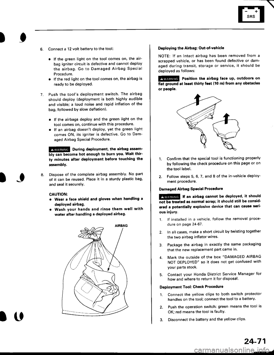
Connect a 12 volt battery to the tool:
. lf the green light on the tool comes on, the aar-
bag igniter circuit is defective and cannot deploy
the airbag. Go to Damaged Airbag Special
Procedure.
. lf the red light on the tool comes on, the airbag is
ready to be deployed.
Push the tool's deployment switch. The airbag
should deploY (deployment is both highly audible
and visible; a loud noise and rapid inflation of the
bag, followed by slow deflation).
. lf the airbags deploy and the green light on the
tool comes on. continue with this procedure.
. l{ an airbag doesn't deploy, yet the green light
comes ON, its igniter is defective. Go to Dam-
aged Airbag Special Procedure.
!!@ During doployment, the airbag sssom'
bly can become hot enough to buln you. Wait thir'
ty minutes aftsr deployment belore touching tho
assembly.
Dispose of the complete airbag assembly. No part
of it can be reused. Place it in a sturdy plastic bag,
and seal it securelY,
CAUTION:
. Wear a fsce shield and gloves when handling a
deployed airbag.
. Wash your hands and rinse them well with
wat6r after handling. deployed airbag.
t('
24-71
7.
AIRAAG
Doploying th6 Airbag: Out-of-vehicle
NOTE: lf an intact airbag has been removed from a
scrapped vehicle. or has been found defective or dam-
aged during transit, storage or service, it should be
deployed as follows:
@ Po3ition the airbag laca up, outdoors on
flat ground at lsast thirty f€€t (t0 ml from any obstacles
or people.
1. Confirm that the special tool is tunctioning properly
by following the check procedure on this page or on
the tool label.
2. Follow steps 5, 6, 7, and I of the in-vehicle deploy-
menl Drocequre.
Damaged Airbag Spacial Procedure
!@ r an airb.g cannot be deployed, it should
iiiTi-treatcd as normal scrap; il should still be consid-
srsd a potontially oxplosive device that can cau3o ssti-
ous iniury.
1. lf installed in a vehicle, lollow the removal proce-
dure on page 24-67.
2. In all cases. make a short circuit by twisting together
the two airbag inflator wires.
3. Package the airbag in exactly the same packaging
that the new replacement part came in.
4. Mark the outside of the box "DAMAGED AIRBAG
NOT DEPLOYED" so it does not get confused with
your Parts stock.
5. Contact your Honda District Service Manager for
how and where to return it for disposal.
Deployment Tool: Check Procedur€
1. Connect the yellow clips to both switch protector
handles on the tool; connect the tool to a battery.
2. Push the operation switch: green means the tool is
OK: red means the tool is faulty
3. Disconnect the battery and the yellow clips.
Page 2094 of 2189
79. Below Center Console82. Behind Glove Box ('96-'98)\
\
80. Below Front Console ('96-'98)83. Below Right Side of Dash Panel
8'1. Behind Right Side of Dash Panel84. Behind Glove Box
\
201 -'l 3
Page 2104 of 2189
139. Behind Glove Box ('99-'00)142. Lett Rear Corner Engine Gompartment (GX)
140. Underside of Rear Shelf ('99-'00 Sedans)143. Right Rear of Engine Compartment (GX)
141. Top Center of Engine (GX)144. Behind Left Kick Panel (GX)
201-23
Page 2185 of 2189
Connectol
or
Terminal
Number of
Cavities/
Color
LocationConnects toNotes
Connector ldentification and Wire Harness Routing
HEATER SUB.HARNESS A
1"t-
Heater Sub-harness A: '96-'98 models
c440
c722
c723
c724
c725
c726
c727
1 6-BLU
7.GRN
2O.GRY
3-GRY
2.NAT
4-BRN
4.GRN
Under middle of dash
Behind middle ot dash
Behind front console
Behind glove box
Below right side of dash
Behind glove box
Behind glove box
Main wire harness
Mode control motor
Heater sub-harness B
A,/C thermostat
Blower motor
Blower motor resistor
Recirculation control motor
Heater Sub-harness Bt '96;98 models
c743
2O-GRY
6-BRN
14-GRN
Behind front console
Behind middle of dash
Behind middle of dash
Heater sub-harness A
Heater fan switch
Heater control panel
u.
HEATER SUB.HARNESS B
l\-
203-44
Page 2186 of 2189
) ._'
Connectol
o1
Terminal
Number ot
Cavltles/
Color
LocationConnects toNotes
Heater Sub-harness A: '99-'00 models
c440
c722
c723
c724
wlzc
c726
c727
c728
c729
c730
16.8LU
7-GRN
24-BLU
3-GRY
2-NAT
3-NAT
4.GRN
1-BRN
5-GRN
4-BRN
Under middle of dash
Behind middle of dash
Behind front console
Behind glove box
Below right side of dash
Behind glove box
Behind glove box
Behind front console
Behind glove box
Behind glove box
Main wire harness
Mode control motor
Heater sub-harness B
A'lC thermostat
Blower motor
Power transistor
Recirculation control motor
Heater sub-harness B
Air mix control motor
Blower motor high relay
Heater Sub-harness B: '99-'00 models
c723
c728
c742
c743
24.BLU
1-BRN
8-GRY
2O.BLK
Behind front console
Behind front console
Behind middle of dash
Behind middle of dash
Heater sub-harness A
Heater sub-harness A
Heater control panel conn€ctor A
Heater control oanel connector B
HEATER SUB.HARNESS A
HEATER SUB-HARNESS B
203-45