Page 1089 of 2189
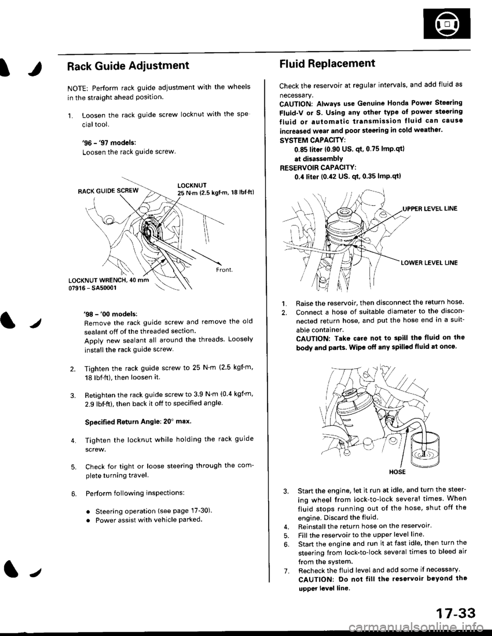
IRack Guide Adjustment
NOTE: Perform rack guide adjustment with the wheels
in the straight ahead Position.
1. Loosen the rack guide screw locknut with the
cialtool.
'96 - '97 models:
Loosen the rack guide screw
'98 - '00 models:
Remove the rack guide screw and remove the old
sealant off of the threaded section.
Apply new sealant all around the threads. Loosely
installthe rack guide screw
Tighten the rack guide screw to 25 N'm (2.5 kgf'm.
18 lbf.ft), then loosen it.
Retighten the rack guide screw to 3 9 N'm (0.4 kgim,
2.9 lbf.ft), then back it off to specified angle.
Specified Return Angle: 20" max.
Tighten the locknut while holding the rack guide
screw.
Check for tight or loose steering through the com-
plete turning travel.
Perform following insPections:
. Steering operation (see page 17-30).
. Power assist with vehicle parked.
4.
LOCKNUT WRENCH, 40 mm
lr
17-33
Fluid Replacement
Check the reservoir at regular intervals, and add fluid as
necessary.
CAUTION: Always us€ Genuine Honda Power Stearing
Fluid-V or S. Using any other type of power sto€ring
tluid or automatic transmission lluid can cause
increased wear and poor steering in cold weathor.
SYSTEM CAPACITY:
0.85 liter 10.90 US' qt,0.75 lmp'qt)
at disassembly
RESERVOIR CAPACITY:
0.4 liter (0.42 US. qt, 0.35 lmP.qt)
LEVEL LINE
LOWER LEVEL LINE
1. Raise the reservoir, then disconnect the return nose.
2. Connect a hose of suitable diameter to the discon-
nected return hose, and put the hose end in a suit-
able container.
CAUTION: Take care not to spill tho fluid on the
body and parts. Wipe off any spill€d fluid at oncs'
3. Start the engine, let it run at idle, and turn the steer-
ing wheel from lock-to-lock several times When
fluid stops running out of the hose, shut off the
engine, Discard the fluid.
4. Reinstall the return hose on the reservoir'
5. Fill the reservoir to the upper level line.
6. Start the engine and run it at fast idle, then turn the
steering trom lock-to-lock several times to bleed air
trom the system.
7. Recheck the fluid level and add some it necessary.
CAUTION: Do not fill the reservoir beYond the
upper l€vel line.
HOSE
Page 1123 of 2189
)
1?
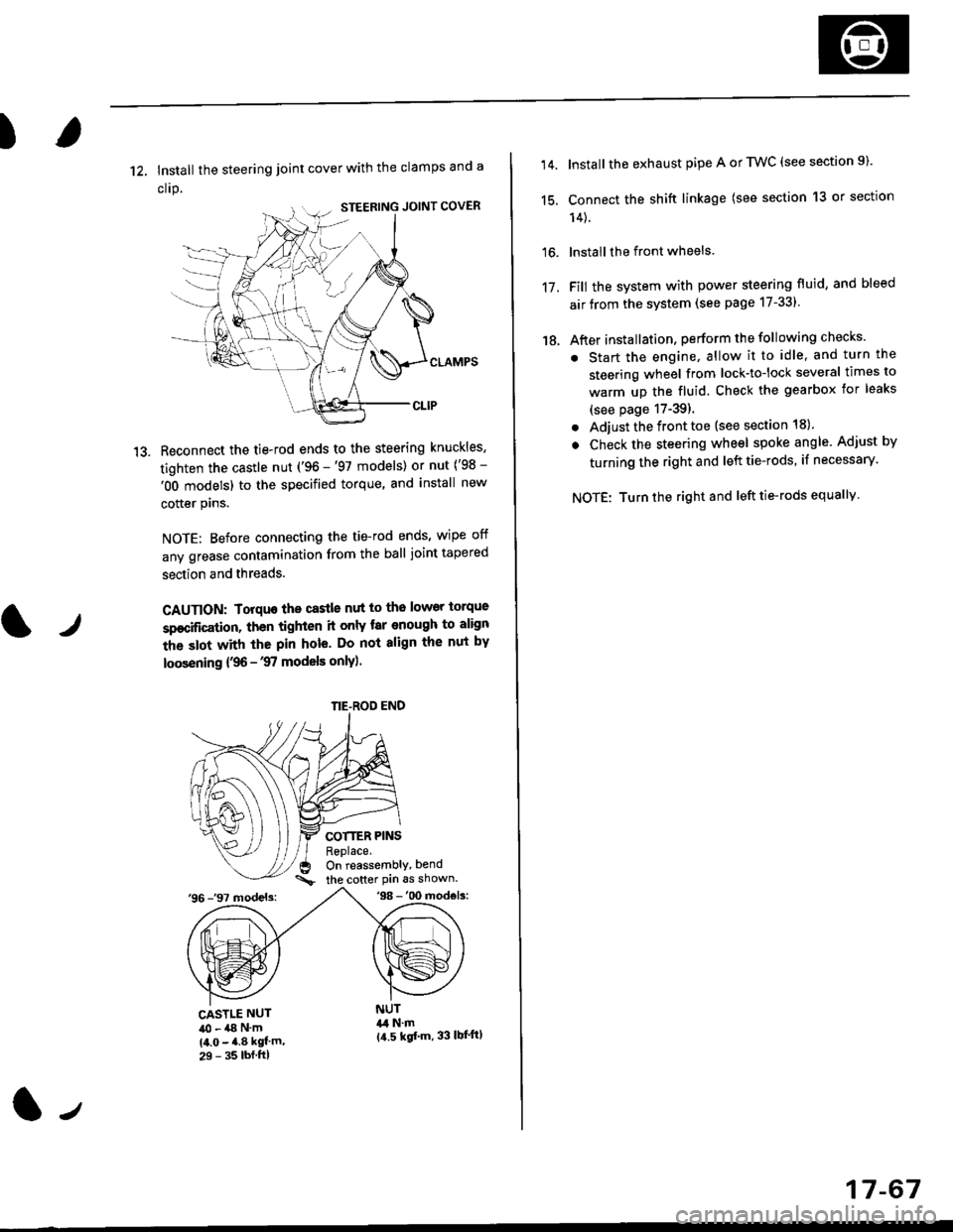
12, Install the steering joint cover with the clamps and a
clrp.
Reconnect the tie-rod ends to the steering knuckles,
tighten the castle nut ('96 -'97 models) or nut ('98 -
'OO models) to the specified torque, and install new
cotter plns.
NOTE: Before connecting the tie-rod ends, wipe off
any grease contamination from the ball joint tapered
section and threads.
CAUTION: Torquo the castle nut to the lower torque
sp€cification, then tighten it only tar enough to align
the slot with the pin hole. Do not align the nut by
loosening {,96 -'97 models only).
COTTER PINSReplace.On reassembly, bend
the cotter Pin 6s shown.'96 -'97 models:'98 -'00 mod€ls:
tr
CASTLE NUT40 - a8 N'm(4.0 - 4.8 kgf'm,29 - 35 lbf.ftl
NUT&l N.m{a.5 kgf'm, 33 lbl'ftl
NE-ROD END
(l-,
17-67
14.
15.
16.
17.
18.
Install the exhaust pipe A or TWC (see section 9).
Connect the shift linkage (see section 13 or section
14).
lnstall the front wheels
Fill the system with power steering fluid, and bleed
air from the system (see page 17-331
After installation, perform the following checks
. Start the engine, allow it to idle, and turn the
steering wheel from lock-tolock several times to
warm up the fluid. Check the gearbox for leaks
(see page 17-39).
. Adjust the front toe (see section 18).
. Check the steering wheel spoke angle. Adjust by
turning the right and left tie-rods, if necessary.
NOTE: Turn the right and left tie-rods equallv
Page 1125 of 2189
)
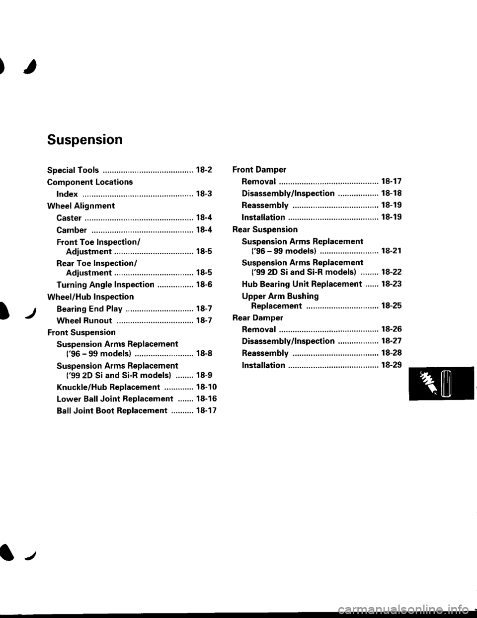
Suspension
Special Tools ............. 18-2
Component Locations
lndex ,,.............. ...... f8-3
Wheel Alignment
Caster .............. ....... 18-4
Camber .................. l8-4
Front Toe Inspection/
Adiustment ........ 18-5
Rear Toe lnspection/
Adiustment ........ 18-5
Turning Angle Inspection ................ 18-6
Wheel/Hub Inspection
Bearing End P|ay .............................. l8-7
Wheel Runout ....... 18-7
Front Suspension
Suspension Arms Replacement
('96 - 99 modelsl .......................... 18-8
Suspension Arms Replacement
('99 2D Si and Si-R models) ........ 18-9
Knuckle/Hub Replacement ............. 18-10
Lower Ball Joint Replacement ....... 18-16
Ball Joint Boot Replacement .......... 18-17
Front Damper
Removal ................. 18-17
Disassembly/1nspection .................. 18-18
Reassembly ........... 18-19
lnstallation ............. 18-19
Rear Suspension
Suspension Arms Replacement
('96 - 99 models) ....................,..... 18-21
Suspension Arms Replacement
('99 2D Si and Si-R models) ........ 1A-22
Hub Bearing Unit Replacement ...... 18-23
Upper Arm Eushing
Replacement .....18-25
Rear Damper
Removal ................. 18-26
Disassembly/|nspection ............. ..... 1A-27
Reassembly ........... 18-28
lnstallation ............. 18-29
lr
Page 1128 of 2189
Wheel Alignment
,f,
Caster
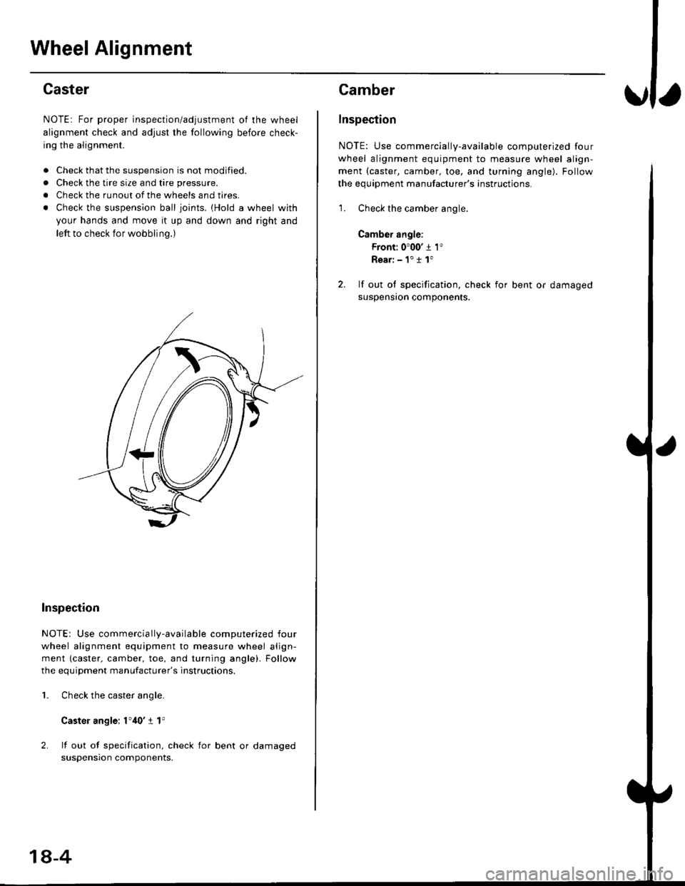
NOTE: For proper inspection/adjustment of the wheel
alignment check and adjust the following before check-
ing the alignment.
. Check that the suspension is not modified.
. Check the tire size and tire pressure.
. Check the runout of the wheels and tires.
. Check the suspension ball ioints. {Hold a wheel with
your hands and move it up and down and right and
left to check for wobbling.)
Inspection
NOTE: Use commercia lly-available computerized four
wheel alignment equipment to measure wheel align-
ment {caster. camber, toe, and turning angle). Follow
the equiDment manufacturer's instructions.
Check the caster angle.
Caster angle: 1',10' I 1'
lf out of specification, check for bent or damaged
suspensron components.
2.
1.
18-4
Camber
lnspection
NOTE: Use commercially-available computerized four
wheel alignment equipment to measure wheel align-
ment (caster, camber, toe, and turning angle). Follow
the equipment manufacturer's instructions.
1. Check the camber angle.
Camber angle:
Front: 0'00' j 1"
Rear:-1"11"
2. lf out ol specification, check for bent or damaged
suspensron components.
Page 1129 of 2189
?
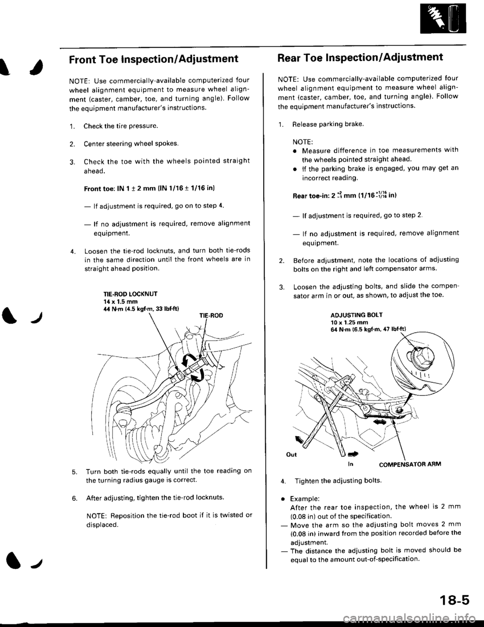
Front Toe Inspection/Adiustment
NOTE: Use commercially-available computerized four
wheel alignment equipment to measure wheel align-
ment (caster, camber, toe, and turning angle). Follow
the equipment manufacturer's instructions.
1. Check the tire pressure.
Center steering wheel spokes.
Check the toe with the wheels pointed straight
a head.
Front toe: lN 1 1 2 mm llN l/16 r 1/16 inl
- lf adjustment is required, go on to step 4.
- lf no adjustment is required, remove alignment
equrpmenr.
Loosen the tie-rod locknuts, and turn both tie-rods
in the same direction until the front wheels are in
straight ahead position.
TIE.ROD LOCKNUT'14 x 1.5 mm
4.
tJ
6.
Turn both tie-rods equally until the toe readang on
the turning radius gauge is correct.
After adjusting, tighten the tie-rod locknuts.
NOTE: Reposition the tie-rod boot if it is twisted or
displaced.
4,1 N.m {4.5 kgf.m, 33 lb{.ft)
2.
Rear Toe Inspection/Adiustment
NOTE: Use commercially-available computerjzed Iour
wheel alignment equjpment to measure wheel align-
ment (caster, camber, toe, and turning angle). Follow
the equipment manufacturer's instructions.
1. Release parking brake.
NOTE:
a Measure difference in toe measurements wlth
the wheels pointed straight ahead.
. if the parking brake is engaged, you may get an
incorrect readang,
Rear toe-in: 2 11 mm ttltollllS int
- lf adjustment is required, go to step 2.
- lf no adjustment is required, remove alignment
equipment.
Before adjustment, note the locations of adiusting
bolts on the right and left compensator arms
Loosen the adjusting bolts, and slide the compen
sator arm in or out. as shown, to adjust the toe
ADJUSTING BOLT10 x 1.25 mm
In CoMPENSAToR ARM
4. Tighten the adiusting bolts
. Example:
After the rear toe inspection, the wheel is 2 mm
(0.08 in) out of the specification.- Move the arm so the adjusfing bolt moves 2 mm
(0.08 in) inward trom the position recorded before the
adjustment.- The distance the adjusting bolt is moved should be
equal to the amount out-of-specification.
64 N.m 16.5 ksf m, 47 lbtft)
18-5
Page 1130 of 2189
Wheel Alignment
Turning Angle Inspection
NOTEr Use commercially-available computerized four
wheel alignment equipment to measure wheel align-
ment (caster, camber, toe, and turning angle). Follow
the equipment manufacturer's instructions.
'1. Turn the wheel right and left while applying the
brake, and measure the turning angle of both
wneets.
Turning angle:
lnward wheel: 39'50'
Outwald wheel (ref erencel: 33'10'
2.lf the turning angle
check for bent or
nents,
is not within the specifications,
da m aged suspension compo-
18-6
Page 1149 of 2189
T
11.
1)
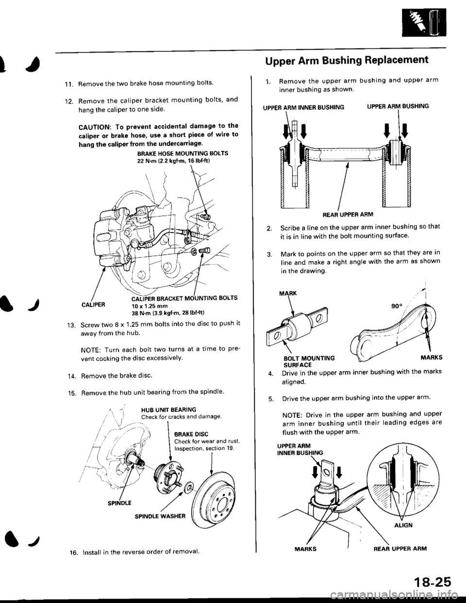
Remove the two brake hose mounting bolts
Remove the caliper b.acket mounting bolts, and
hang the caliPer to one side
CAUTION: To prevent accidental damage to the
caliper or brake hose, use a short piece of wile to
hang the caliper from the undercarriage.
BRAKE HOSE MOUNTING BOLTS
22 N'm {2.2 kgf'm, 16lbt"ft}
CALIPER 10 x 1.25 mm38 N'm (3.9 kgf'm, 28 lbf'ftl
Screw two 8 x 1.25 mm bolts into the disc to push it
away from the hub.
NOTE: Turn each bolt two turns at a time to pre-
vent cocking the disc excessively.
Remove the brake disc.
Remove the hub unit bearing from the spindle
SPINOLE WAS}IER
lr
14.
15.
lt
16. lnstall in the reverse order of removal.
1A-25
Upper Arm Bushing RePlacement
1. Remove the upper arm bushing and upper arm
jnner bushing as shown
UPPER ARM INNER BUSHING UPPER ARM BUSHING
REAR UPPER ARM
Scribe a line on the upper arm inner bushing so that
it is in line with the bolt mounting surface
Mark to points on the upper arm so that they are In
line and make a right angle with the arm as shown
in the drawing.
BOLT MOUNTINGSURFACE
Drive in the upper arm inner bushing with the marks
aligned.
Drive the upper arm bushing into the upper arm
NOTE: Drive in the upper arm bushing and upper
arm inner bushing until their leading edges are
flush with the uPPer arm
ttI
5.
UPPER ARM
Page 1252 of 2189
Doors
Glass Adjustment {cont'd)
c. Tighten the roller guide bolts.
d. Loosen the front channel bolts.
e. Lower the glass.
f. Push the front channel against the glass, then
tighten the mounting bolts.
MOUNTINGBOLT
3. Check that the glass moves smoothly.
4. Raise the glass fully and check for gaps.
5. Check the glass operation.
NOTE: Check that the glass contacts the glass run
channel evenly.
WEATHERSTRIP
GLASS
U
-\,
20-22
6. Check for water leaks.
Spray water over the roof and on the sealing area
as shown.
NOTE:
. Adjust the water pressure as shown.
. Do not squeeze the tip of the hose.
0.5 m {1.6ft)
HOSE
Attach the plastic cover, then install the door panel
(see pages 20 4, 10, 16).
Install the regulator handle so it points forward and
up at a 45 degree angle with the glass closed.
Forward -
1.
HOSE
300 mm {11.8 in)