Page 682 of 2189

Description
(cont'dl
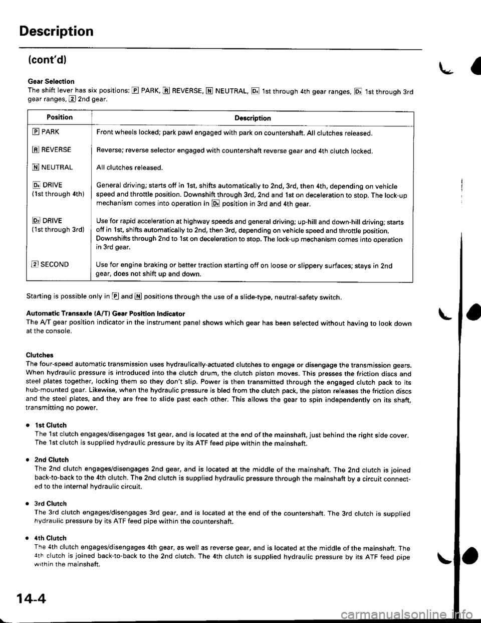
Gear Selection
The shift lever has six positions: E PARK. E REVERSE, N NEUTRAL, E 1st through 4th gear ranges, E 1st through 3rdgear ranges, @ 2nd gear.
Starting is possible only in E and E positions through the use of a slide-type, neutral-safety switch.
Automatic Transaxle (A/f, Gear Position Indicator
The Ay'T gear position indicator in the instrument panel shows which gear has been selected without having to look downat the console.
Clutch€s
The four-speed automatic transmission uses hydraulically-actuated clutches to engage or disengage the transmission gears.When hydraulic pressure is introduced into the clutch drum, the clutch piston moves. This presses the friction discs andsteel plates together, locking them so they don't slip. Power is then transmitted through the engaged clutch pack to itshub-mounted gear. Likewise, when the hydraulic pressure is bled from the clutch pack, the piston releases the friction discsand the steel plates, and they are free to slide past each other. This allows the gear to spin independently on its shaft,transmitting no power.
lst Clutch
The 1st clutch engages/disengages 1st gear, and is located at the end of the mainshaft, just behind the right sroe cover.The 1st clutch is supplied hydraulic pressure by its ATF feed pipe within the mainshaft.
2nd Clulch
The 2nd clutch engagegdisengages 2nd gear, and is located at the middle of the mainshaft. The 2nd clutch is joined
back-to-back to the 4th clutch. The 2nd clutch is supplied hydraulic pressure through the mainshaft by a circutr connect-ed to the internal hvdraulic circuit,
3rd Clutch
The 3rd clutch engages/disengages 3rd gear, and is located at the end of the countershaft. The 3rd clutch is suooliedhydraulic pressure by its ATF feed pipe within the countershaft.
ilth Clutch
The 4th clutch engages/disengages 4th gear, as well as reverse gear, and is located at the middle of the mainshaft. The4th clutch is joined back-to-back to the 2nd clutch. The 4th clutch is supplied hydraulic pressure by its ATF feed pipewith in the mainshaft.
\-a
PositionDe3cription
E PARK
E REVERSE
N NEUTRAL
E DRIVE
{1st through 4th)
Ei DRtvE('lst through 3rd)
B SECOND
Front wheels locked; park pawl engaged with pa* on countershaft. All clutches released.
Reverse; reverse selector engaged with countershaft reverse gear and 4th clutch locked.
All clutches released.
General driving; starts off in 1st, shifts automatically to 2nd, 3rd, then 4th, depending on vehiclespeed and throttle position. Downshift through 3rd, 2nd and 1st on deceleration to stop. The lock-upmechanism comes into operation in @ position in 3rd and 4th gear.
Use for rapid acceleration at highway speeds and general driving; up-hill and down,hill dfiving; stansotf in 1st, shifts automatically to 2nd, then 3rd, depending on vehicle speed and throttle position.
Downshifts through 2nd to lst on deceleration to stop. The lock-up mechanism comes into operationin 3rd gear,
Use for engine braking or better traction starting off on loose or slippery surfaces; stays in 2ndgear, does not shift up and down.
14-4
Page 703 of 2189
\
@ Position
As the engine turns, the ATF pump also starts to operate, Automatic transmission fluid (ATF) is drawn from (99) and dis-
charged into (1). Then, ATF flowing from the ATF pump becomes the line pressure (1). The line pressure (1) is regulated
by the regulator valve. The torque conv€rter inlet pressure (92) enters (94) of the torque converter through the lock-up
shift valve and discharges into (901. The torque converter ch€ck valve prevents the torque converter pressure from rising'
Under this condition, the hydraulic pressure is not applied to the clutches'
NOTE: When used, "1eft" or "right" indicates direction on the hydraulic circuit'
14-25
Page 704 of 2189

Description
Hydraulic Flow (cont'd)
L?j Position
The line pressure (1) flows to the manual valve and the modulator valve. The line pressure (1) changes the trne pressure(4) and (25) at the manual valve. and changes to the modulator pressure at the modulator valve. But the moourator pres-sure (6) does not flow to each shift valve because shift control solenoid valves A and B are turned oN by the pcM. Theline pressure (4) passes through the cPB valve and the cPc valve. and changes to the line pressure (s), th;n flows to the1-2 shift valve. The line pressure {S) from the l-2 shift valve changes to the 2nd clutch pressure (20) at the 2-3 shift valve.The 2nd clutch pressure (20) is applied to the 2nd clutch. and the 2nd clutch is engaged. The line pressure (4) passesthrough the 1-2 shift valve and the orifice, and changes the lst clutch pressure, The 1st clutch pressure (10) atso flows tothe 1st clutch. However, no power is transmitted because of the one_way clutch.
NOTE: When used, "Ieft" or "right" indicates direction on the hvdraulic circuit.
14-26
Page 705 of 2189
E! or l8! Position
1. lst Gear
The flow of fluid through the torque converter circuit is same as in E position, The line pressure tlows to the manual
valve and the modulator valve. The line pressure changes to the modulator pr€ssure (6) at the modulator valve and to
the line pressure (4) at the manual valve. The modulator pressure (61 flows to the lsft end of the 1-2 shift valve and the
3-4 shift valve because shift control solenoid valve A is turned OFF and B is turned ON by the PCM. The 1-2 shift valve
is moved to the right side. The line pressure (4) changes to the lst clutch pressure (10) at the 1-2 shift valve and the
oritice. The lst clutch pressure (10) is applied to the 1st clutch and tho 1st accumulator; consquently, the vehicle will
move as the engine power is transmitted.
NOTE: When used, "|eft" or "right" indicates direction on the hydraulic circuit'
(cont'd)
14-27
Page 706 of 2189
Description
Hydraulic Flow (cont'd)
2nd G.!r
As tha speed of the vehicle reaches the prescribed value, shift control solenoid valve A is turned oN by means of thePCM The modulator pressure {64} in the left end of the 1-2 shift valve is r€leased by turning shift controt sotenoidvalve A oN The 1-2 shift valve is moved to the left side and uncovers the port to allow line pressure {5) to the z-3shift valve. The line pressure (5) changes to the 2nd ctutch pfessure l2O) at the 2-3 shift valve. The 2nd clutch pressure(20) is applied to the 2nd clutch, and the 2nd clutch is engaged.
Fluid flows by way of:- Line Pressure (4) + cPB varve - Line pressure (s) * 'r-2 shift varve - Line pressure (5) * 2-3 shift varve- 2nd Clutch Pressure (20) + 2nd Clutch
The hydraulic pressure also flows to the 1st clutch. However, no power is transmittod because of the one-way ctutch.
NOTE: When used, "|eft" or ,,right,, indicates direction on the hydraulic circuit.
\-
14-28
Page 707 of 2189

I
3. 3rd Gear
As the soeed of the vehicle reaches the prescribed value, shift control solenoid valve B is turned OFF by means ol the
pCM. Shift control solenoid valve A remains ON. The modulator pressure (6) flows to the right end of the 1-2 shift
valve and the left end oJ the 2-3 shift valve. The 2-3 shift valve is moved to the right side by the modulator pressure
(68). The 2-3 shift valve covers the port to stop line pressure (5) to the 2nd clutch and uncovers to the 3-4 shift valve
as the 2-3 shift valve is moved to the right side. The line pressure (5) becomes the 3rd clutch pressure (30) at the 3-4
shift valve. The 3rd clutch pressure (30) is applied to the 3rd clutch, and the 3rd clutch is engaged'
Fluid flows by way of:- Line Dressure (4) * CPB Valve - Line Pressure (5) * 1-2 Shift Valve - Line Pressure (5) * 2-3 Shift Valve
- Line Pressure (5) * 3-4 Shift Valve - 3rd Clutch Pressure (30) - 3rd Clutch
The hvdraulic pressure also flows to the 1st clutch. However, no power is transmitted because of the one-way clutch
as in 2nd gear.
NOTE: When used, "|eft" or "right" indicates direction on the hydraulic circuit.
14-29
Page 708 of 2189

Description
Hydraulic Flow lcont'dl
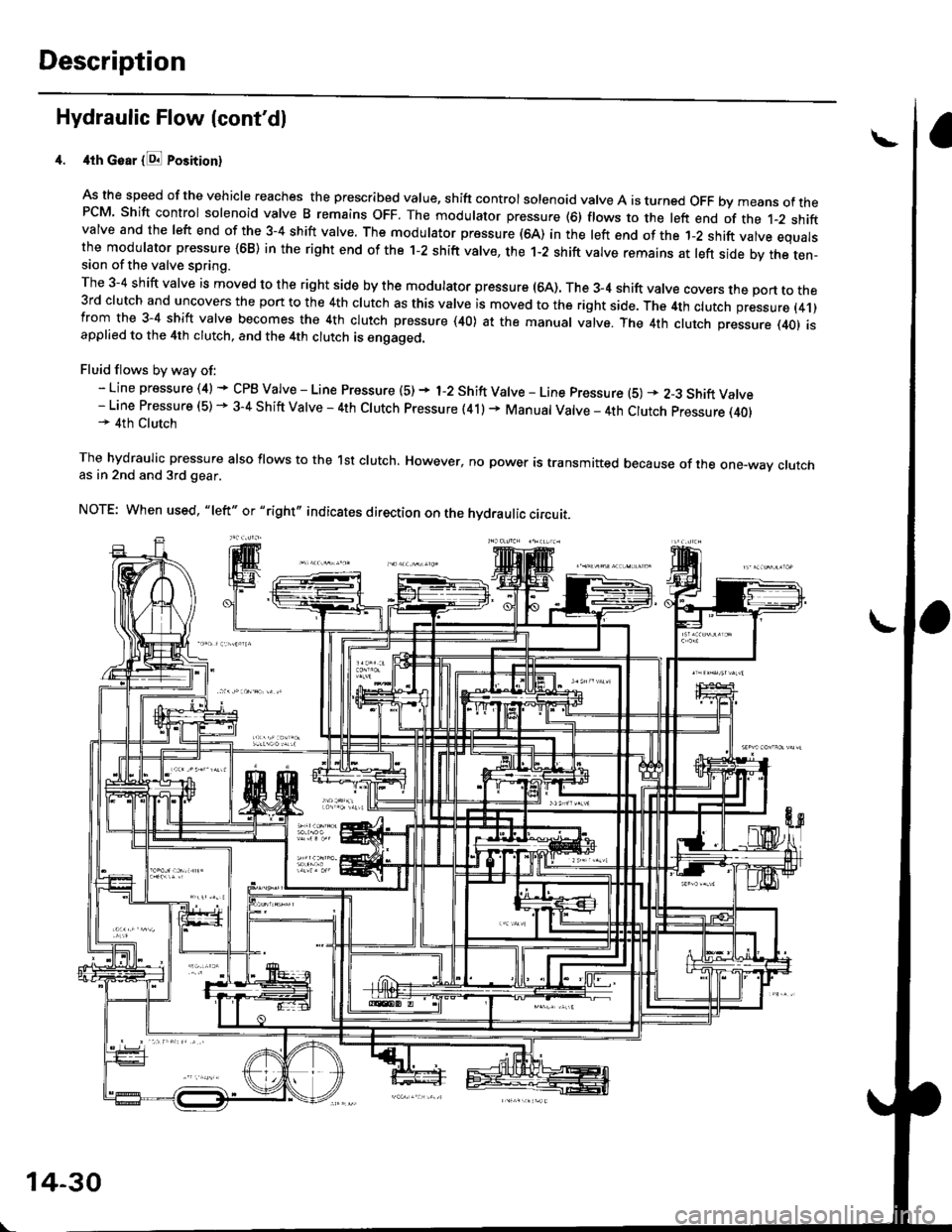
4th Goar {E Position}
As the speed of the vehicle reaches the prescribed value, shift controlsolenoid valve A is turned OFF bymeans ofthePCM Shift control solenoid valve B remains oFF. The modulator pressure (6) flows to the left end of the t-2 shiftvalve and the left end of the 3-4 shift valve. The modulator pressure (64) in the left end of the 1-2 shift valve equalsthe modulator pressure {68) in the right end of the 1-2 shift valve, the 1-2 shift valve remains at left side by the ten-sion of the valve spring.
The 3-4 shift valve is moved to the right side by the modulator pressure (64). The 3_4 shift valve covers the port to the3rd clutch and uncovers the port to the 4th clutch as this valve is moved to the right side. The 4th clutch pressure (4.1)from the 3-4 shift valve becomes the 4th clutch pressure (40) at the manual valve. The 4th clutch pressure (401 isapplied to the 4th clutch, and the 4th clutch is engaged.
Fluid flows by way of:- Line pressure (4) * CPB Valve - Line Pressure (5) + 1-2 Shift Valve - Line pressure (5) * 2-3 Shift Valve- Line Pressure (5) - 3-4 Shift Valve - 4th Clutch pressure (41) + Manual Valve _ 4th Clutch pressure (40)* 4th Clutch
The hydraulic pressure also flows to the lst clutch. However, no power is transmitted because of the one-way crutchas in 2nd and 3rd gear.
NOTE: When used, "|eft" or "right,, indicates direction on the hydraulic circuit.
\
14-30
Page 709 of 2189

L
E Position
The flow of fluid through the torque convefter circuit is the same as in E position The line pressure (1) changes to the
line pressure (3) and flows to the l-2 shift valve. The iine pressure (3) changes to the line pressure (3') at the 'l-2 shift valve
and flows to the servo valve. The servo valve is moved to the right side (Reverse range position) and uncovers the port to
allow line pressure {3") to the manual valve, The line pressure {3') from the 1-2 shift valve flows through the servo valve to
the manual valve and changes the 4th clutch pressure (40). The 4th clutch pressure (40) is applied to the 4th clutch, and
the 4th clutch is engaged,
Reverse Inhibitor Control
When the E position is selected while the vehicle is moving forward at spe€ds over 6 mph (10 km/h)' the PCM outputs the
1st speed signal to shift control solenoid valves A and B; shift control solenoid valve A is turned oFF, shift control solenoid
valve B is turned ON. The 1-2 shift valve is moved to the right side and covers the port to stop line pressure (3') to the
servo valve. The line pressure (3'�) is not applied to the servo valve, and the 4th clutch pressure (40) is not applied to the
4th clutch, as a result, power is not transmitted to the reverse direction'
When used. 'left" or "right" indicates direction on the hydraulic circuit'
14-31