Page 164 of 2189
VTEC Solenoid ValveVTEC Rocker Arms
a
I
(
Inspection
1. Remove the VTEC solenoid valve assembly fromthe cylinder head. and check the VTEC solenoidvalve filter for clogging.
. lf there is clogging, replace the engine oilfilter andengine oil.
6x1.0mm12 N.m (1.2 kgf.m, B,7 tbf.ftl
lf the filter is not clogged. push the VTEC solenoidvalve with your finger and check its movemenr.
. lf the VTEC solenoid valve is normal, check theengine oil pressure.
6x1.0mm12 N.m (1.2 kgtm,8.7 lbt.ft)
6-54
L-
SOLENOID
Manual Inspection
1. Set the No. 1 piston at TDC.
2. Remove the ignition wire cover and the wires.
3. Remove the ignition clamps while pulling up on theIock.
6xl.0mm9.8 N.m (1.0 kgl.m, 7.2 tbtftl
IGNITIONWIRE COVER
IGNITIONWIRE
\
LOCK
Page 165 of 2189

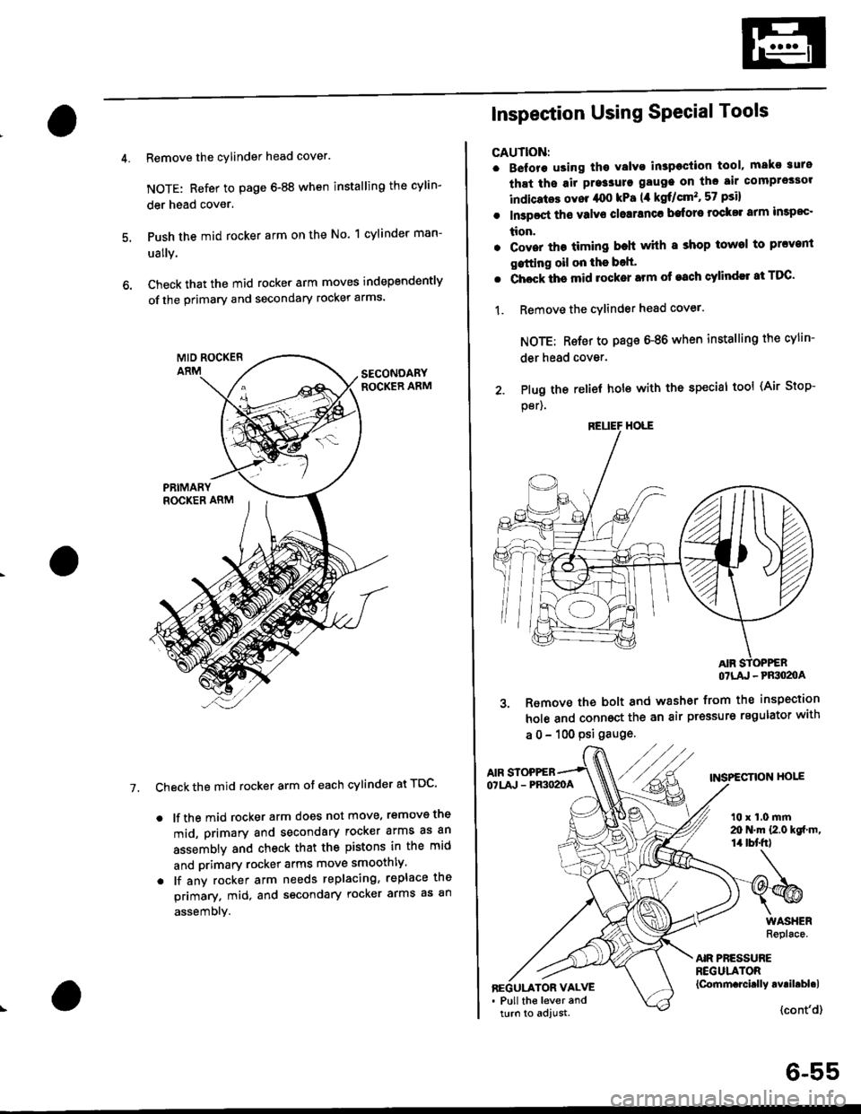
Remove the cylinder head cover.
NOTE: Refer to page 6-88 when installing the cylin-
der head cover.
Push the mid rocker arm on the No. 1 cylinder man-
ually.
Check that the mid rocker arm moves independently
of the primary and secondary rocker arms.
Check the mid rocker arm ot each cylinder at TDC'
. lf the mid rocker arm does not move, removs the
mid, primary and secondary rocker arms as an
assembly and check that the pistons in the mid
and primary rocker arms move smoothly.
. lf any rocker arm needs replacing, replace the
primary. mid, and secondary rocker arms as an
assembly.
7.
2. Plug the
per).
Inspection Using SPecial Tools
CAUTION:
. B€fore using tho Yalvo inspeciion tool, mako suro
that ths air pre3sure gauge on the air comprossor
indicatos ovor /rco kPa (,1 kgf/cm'�, 57 psi)
. In3poct ths valve closranca bafore rock$ arm impoc'
tion.
. Cover the timing beh whh I shop towel to prcvenl
gstting oil on the bolt'
. Chock ths mid rocker arm of each cylindll at TDC'
1. Remove the cYlinder head cover.
NOTE: Rsfer to page 6-86 when installing the cylin-
der head cover.
relief hole with the special tool (Air Stop-
OTLA' - PRSO2OA
3. Remove the bolt and washer from the inspection
hole and connoct the an air pressure regulator with
a 0 - 100 psi gauge.
AIF STOPPEBTNSPECTION HOIEOTLA' - PR3O2OA
t0 x 1.0 mrn20 N.m {2.0 kgf m,14 tbt'fr)
AIR PRESSUREREGULATOR{Cornm.rcirlly avril.bl.lBEGULATOR VALVE. Pull the lever andturn to adjust.{cont'd}
6-55
Page 167 of 2189

Valve Glearance
Adjustment
NOTE:
. Valves should be adjusted only when the cylinder
head temperaturs is less than 100'F (38'C)'
. After adjusting, retorque the crankshaft pulley bolt to
177 N.m (18.0 kgf'm, 130 lbt'ft)
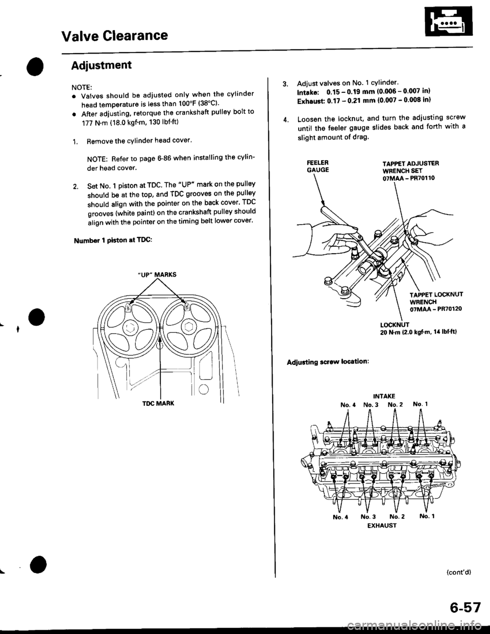
1. Remove the cylinder head cover'
NOTE: Refer to page G86 when installing the cylin-
der head cover.
2. Set No. 1 pi$on at TDC. The "UP" mark on the pullsy
should be at the top, and TDC grooves on the pulley
should align with the pointer on the back cover' TDC
grooves {white paint) on the crankshaft pulley should
align with the pointer on the timing belt lower cover'
Number I Piston at TDC:
4.
Adjust valves on No. 1 cylinder.
lntako: 0.15 - 0.19 mm {0'006 - 0.007 in)
ExhaGt 0.17 - 0.21 mm {0'007 - 0 008 inl
Loosen the locknut, and turn the adjusting screw
until the feeler gauge slides back and forth with a
slight amount of drag.
TAPPET ADJUSTERWFENCH SET07MM - PR70110
TAPPET LOCKNUTWRENCH07MAA - PR70120
Adiusting sclaw location:
LOCKNUT20 N.m {2.0 kgf'm, lil lbt'ftl
(cont'd)
6-57
Page 179 of 2189
WATER BYPASS
HOSE
14. Remove the upper radiator hose, heater hose and
water bvpass hose.
HEATER
Remove the engine wire harness connectors and wlre
harness clamps from the cylinder head and the intake
manifold.
Four fuel injector connector
Engine coolant temperature (ECT) sensor connec-
tor
ECT gauge sending unit connector
ECT switch connector
ldle air control (lAC) valve connector
Manifold absolute pressure (MAP) sensor connec-
tor
Throttle position sensor connector
Primary Heated oxygen sensor (Primary HO2S)
connecror
VTEC solenoid valve connector
15.
a
a
a
a
a
\
16.
17.
Remove the spark plug caps and distributor form
the cylinder head.
Remove the upper bracket.
NOTE:
. Use a jack to support the engine before removing
the upp€r bracket is removed.
. Place a cushion between the oil panandthejack.
12 x 1.25 fin74 N.m 17.5 kgtm,
UPPER BRACKET
18. Remove the cylinder head cover.
{cont'd)
6-69
Page 196 of 2189

Cylinder Head
Installation (cont'dl
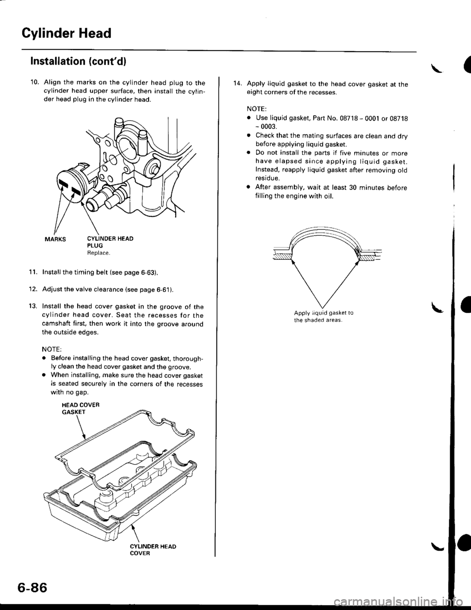
10. Align the marks on the cylinder head plug to thecylinder head upper surface, then install the cylin,
der head plug in the cylinder head.
PLUGReplace.
Install the timing belt (see page 6-63).
Adjust the valve clearance (see page 6-61).
Install the head cover gasket in the groove of the
cylinder head cover. Seat the recesses for the
camshaft first, then work it into the groove around
the outside edges,
NOTE:
. Before installing the head cover gasket, thorough-ly clean the head cover gasket and the groove.
. When installing, make sure the head cover gasket
is seated securely in the corners of the recesses
wrrn no gap.
11.
13.
1'
CYLINDEB HEAD
HEAD COVEB
6-86
(\
14. Apply liquid gasket to the head cover gasket at theeight corners of the recesses.
NOTE:
. Use liquid gasket, Part No. 08718 - 0001 or 08718- 0003.
. Check that the mating surfaces are clean and drybefore applying liquid gasket
. Do not install the parts if five minutes or morehave elapsed since applying tiquid gasket.
Instead, reapply liquid gasket after removing oldrestdue.
. After assembly. wait at least 30 minutes before
filling the engine with oil.
Page 278 of 2189

'99 - 00 models:
EVAPORATIVE EMISSIONIEVAP} PURGE CONTROLSOLENOID VALVETroubleshooting, page 1 1'288FUEL GAUGE SENDING UNITTesting, see section 23
FUEL VAPOR PIPE
ONBOARD REFUELING VAPORR€COVERY IORVRIVENT SHUT VALVETest, page 11 296
EVAPORATIVE EMISSION
{EVAP) CONTROL CANISTERVENT SHUT VALVETroubleshooting, Page 1 1_288
EVAPORATIVE EMISSION
FUEL FILTERBeplacement, page 11-235
FUEL FEED PIPE
FUEL RETURN PIPE
FUEI- PUMPTesting, page 11 236Replacement, page 11-236
FUEL FILLCAP
{EVAPI CONTROLTroubleshooting, page 1 1_288
FUELPULSATION DAMPEB
FUEL INJECTORSReplacement, page 1 1'232
FUEL PRESSUREREGULATOR
EVAPORATIVE EMISSION
{EVAP) BYPASS SOLENOIDVALVETroubleshooting, page 1 1-288
FUELRAIL
FUEL TANK PRESSURESENSOBTroubleshooting, Page 1 1'274
EVAPORATIVE EMISSIONIEVAPI TWO WAY VALVETesting, page 11 295
Testing, page 11-234Replacement, page 11 234FUEL TUBE/OUICK.CONNECTFITTINGSPrecautions, page 1 l-227Disconnection, page 11 227Connection, page 1 1-228
Replacement, page 1 1-241
I(cont'd)
1 1-9
Page 290 of 2189
![HONDA CIVIC 1996 6.G Workshop Manual D16Y5 engine (99 - 00 modelsl:
O) PRIMARY HEATED OXYGEN SENSOR (PBIMARY HO2S,
SENSOR 1)
O SECONDARY HEATEO OXYGEN SENSOR {SECONDARY
HO2S. SENSOR 2)
6] MANIFOLD ABSOLUTE PRESSURE IMAPI SENSOR
rO CruCI HONDA CIVIC 1996 6.G Workshop Manual D16Y5 engine (99 - 00 modelsl:
O) PRIMARY HEATED OXYGEN SENSOR (PBIMARY HO2S,
SENSOR 1)
O SECONDARY HEATEO OXYGEN SENSOR {SECONDARY
HO2S. SENSOR 2)
6] MANIFOLD ABSOLUTE PRESSURE IMAPI SENSOR
rO CruCI](/manual-img/13/6068/w960_6068-289.png)
D16Y5 engine ('99 - 00 modelsl:
O) PRIMARY HEATED OXYGEN SENSOR (PBIMARY HO2S,
SENSOR 1)
O SECONDARY HEATEO OXYGEN SENSOR {SECONDARY
HO2S. SENSOR 2)
6] MANIFOLD ABSOLUTE PRESSURE IMAPI SENSOR
rO CruCIruC COOUruT TEMPERATURE IECTI SENSOR
o rrurlxe ln ETUpERATURE 0AT) SENSOR
.d KNOCK SENSOR (KS}
O CN,NruXSXITT SP:ED FLUCTUATION (CKFI SENSOR
@ rou an corurnoL 0Ac) valvE
O THROTTLE BODY (TB)
@ FUEL INJECTOR
E) FUEL PULSATION OAMPER
t? FUEL FILTER
G) FUEL PRESSURE REGULATOR
OI FUEL PUMP (FP)
Gi FUEL TANK
G) AIR CLEANERfi? RESONATOR
Gl posmvr cnglrcAsE VENTILATION (PCV) VALVE
@ EXHAUST GAS RECIRCULATION IEGR} CONTROL
SOLENOID VALVE6 EXHAUST GAS RECTRCULATION (EGR) VAI-VE
rf exxlust cls nectRcuLATloN IEGR) vALvE LIFT
SENSOR@ EVAPORATIVE EMISSION (EVAPI PURGE CONTNOL
SOLENOID VALVE
O} PURGE JOINTio :vaponanve eutssloN (EVAP) coNTRoL cANlsrER
d rvlponlrtve EmtsstoN tEvAPl BYPASS soL-eNolD
VALVE
6 EVAPORATIVE EMISSION {EVAP) CONIROL CANISTER
FILTER
@ EVAPORATIVE EMISSION (EVAPI CONTROL CANISTER
VENT SHUT VALVEOA FUEL TANK PRESSURE SENSOR
6 :vlponlnvg er,/tlssloN tEvAPl TWO WAY VALVE
6 oNgoano nerueltNc vAPoR REcovERY {onvRl VENT
SHUT VALVE
€!) ONBOARD REFUELING VAPOR RECOVERY (ORVRI VAPOR
RECIBCULATION VALVE
@ THREE WAY CATALYTIC CONVERTER (TWCI
(cont'd)
11-21
L
Page 293 of 2189
![HONDA CIVIC 1996 6.G Workshop Manual System Description
Vacuum Connections (contdl
D16Y8 engine l99 - 00 modetsl:
(]-i PAIMARY HEATEO OXYGEN SENSOR {PRIMARY HO2S,SENSOR 1)..2r SECONOARY HEATEO OXycEN SENSOB ISECONDARYHO2S, SENSOR 2li3) HONDA CIVIC 1996 6.G Workshop Manual System Description
Vacuum Connections (contdl
D16Y8 engine l99 - 00 modetsl:
(]-i PAIMARY HEATEO OXYGEN SENSOR {PRIMARY HO2S,SENSOR 1)..2r SECONOARY HEATEO OXycEN SENSOB ISECONDARYHO2S, SENSOR 2li3)](/manual-img/13/6068/w960_6068-292.png)
System Description
Vacuum Connections (cont'dl
D16Y8 engine l'99 - 00 modetsl:
(]-i PAIMARY HEATEO OXYGEN SENSOR {PRIMARY HO2S,SENSOR 1)..2r SECONOARY HEATEO OXycEN SENSOB ISECONDARYHO2S, SENSOR 2li3) MANIFOLD ABSOLUTE PBESSURE {MAPI SENSORO ENGINE cooLANT TEMPERATURE (ECTI sENsoR(5) INTAKE AIR TEMPERATURE {IAT} sENsoRG] KNOCK SENSOR IKSI?r CRANKSHAFT SPEEo FLUCTUATTON {CKF) SENSOR.O IDLE AIR coNTRoL {IAc)vALvEi-9] THROTTLE BOOY {TB)(O FUEL INJECToRI]'i FUEL FILTER.O FUEL PRESSURE REGULAToR[t FUEL PUMP {FPl.D FUEL TANKil' AIR CLEANERTD RESONATORO FUEL TNJEC oN AtR tFtA) coNTRoL vAt_vE.19 POSITIVE CRANKCASE VENTILATION {PCVI VALVE
.19) EVAPORATIVE EMIssIoN {EVAP) PURGE coNTBoLSOLENOID VALVE€g PURGE JorNTtj EVApoRATtvE EMtsstoN {Evap} coNTRoL cANtsTERC4 EVAPONANVE EMISSION (EVAP) BYPASS SOLENOIDVALVE
?3 EVAPORATIVE EMISSION {EVAP} CONTROL CANISTERFILTERA4 EVAPoBATIVE EMIssIoN (EVAP) coNTRoL CANISTERVENT SHUT VALVEC! FUEL TANK PRESSURE sENsoREO EVAPOBATIVE EMISSION (EVAP) TWO WAY VALVEe? oNBoARD REFUELtiIG vApoR REcovERy {oRvR} VENTSHUT VALVE@ oNBoARD REFUELTNG vapoR REcovERy (oRvR) vapoRRECIRCULATION VALVEiP THREE WAY CATAI.YTIC CONVEBTER {TWCI
'- *o'*- -
COOLANT
]L
nrl
L
ii8'x'", *
--j IIM TTI ^n 14 [l(2i)-fr l-1ry|
11-24