1996 HONDA CIVIC Valve cover
[x] Cancel search: Valve coverPage 1175 of 2189
Master Cylinder/Brake Booster
IRemovaUlnstallation
CAUTION:
. Be care{ul nol to bend or damage the brake lines when
rsmoving the mastsr cYlinder.
. Do not soill brakefluid on the vehicle; it may damage
the paint; if brake fluid does contact the paint, wssh
it off immediatelY with water'
. To prevent spill3, cover the hose ioints with rags or
shop towels.
9. Remove the four booster mountlng nuts
10. Pull the brake booster forward until the clevis is
clear of the bulkhead.
11. Remove the brake booster from the engine com-
panmenr.'12. Install the brake booster and master cylinder in the
reverse order of removal.
CAUTION:
. When connecting the brake lines. make sure
that there is no inte erence between the brake
lines and oth6r Parts.
r Be careful not to bend or damage the brake lines
when installing the master cylinder.
NOTE: lf replacing the master cylinder or brake
booster, check and adiust the pushrod clearance
be{ore installing the master cylinder (see page 19-221'
Fill the master cylinder reservoir, and bleed the
brake svstem (see Page 19-7).
After installation. check the brake pedal height and
brake pedal tree play (see page l9-5) and adjust if
necessary.
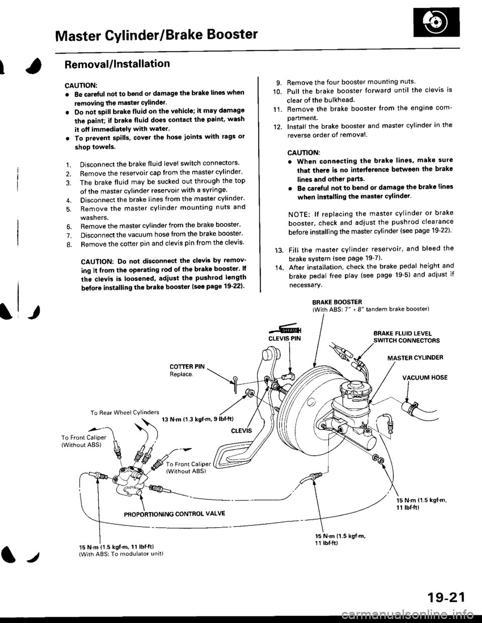
BRAKE BOOSTER(With ABS: 7" + 8" tandem brake booster)
BRAKE FLUIO LEVELSWITCH CONNECTORS
MASTER CYLINDER
VACUUM HOSE
1.
2.
3,
5.
Disconnect the brake fluid level switch connectors'
Remove the reservoir cap from the master cylinder'
The brake fluid may be sucked out through the top
of the master cylinder reservoir with a syrlnge.
Disconnect the brake lines from the master cylinder'
Remove the master cylinder mounting nuts and
washers.
\l/
6. Remove the master cylinder from the brake booster'
7. Disconnect the vacuum hose trom the brake booster'
8. Remove the cotter pin and clevis pin from the clevis'
CAUTION: Do not disconnect the clevb by remov-
ing it from the operating rod of the brako booster' lf
the clevis is loosened, adiust the pushrod length
before installing th€ brake booster (see page 19-221'
COTTER PINReplace.
To Rear Wheel Cylinders
14.
-6.4CLEVIS PIN
To Front Caliper(Without ABS)$
t'N't'ttrnt'-''
To Front CaliperlWithout ABSi
PBOPORTIONING CONTROL VALVE
15 N.m {1.5 kgl m,11 tbtft)
15 N.m {1.5 kgif.m, 11 lbtft}(With ABS: To modulator unit)lr
19-21
Page 1416 of 2189
Heater Control Panel
'95 - 98 modolsi
Remove the driver's dashboard lower cover, the
glove box and the center dashboard lower cover(see section 20).
Disconnect the air mix control cabls from the heater
unit {see page 21-44).
Remove the rear window defogger switch, the hazard
warning switch and the audio unit (see section 23).
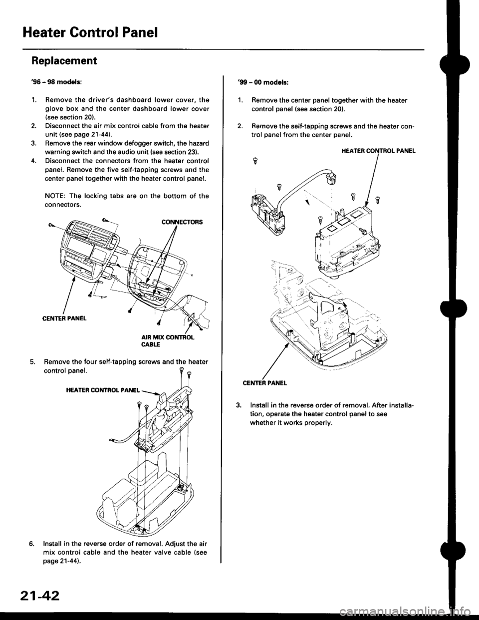
Disconnect the connectors from the heater control
panel. Remove the five self-tapping screws and the
center panel together with the heater control panel.
NOTE: The locking tabs are on the bottom of the
connecrors.
Install in the .everse order of removal. Adjust the air
mix control cable and the heater valve cable {seepage 21-44)..
Replacement
1.
Remove the four self-tapping screws and the heater
21-42
1.
'9!, - 00 modols:
Remove the center panel together with the heater
control panel (see section 20).
Remove the self-tapping screws and the heater con-
trol panelfrom the center Danel.
Install in the reverse order of removal. After
tion, operate the heater control panel to see
whether it works properly.
installa-
Page 1425 of 2189
Air Conditioning
Speciaf Tools ......'.....' 22-2
f f f ustrated f ndex ......................... ".......' 22-3
Wiring/Connector Locations'.........'.... 22'4
Description
Outfine ............ .......22-s
Circuit Diagram
'96 - 98 Models ......"..........".......'.... 22-6
'99 Modef """""""' 22-7
Troubleshooting
Symptom Chart ".'......""................. 22-8
Flowcharts
Condenser Fan .........".................,..'. 22-9
Compressor .....""" 22-12
A/C System .........'.22'17
A/C Thermostat
Test ........'.......' """'22'21
Relays
Test ....."'......... ..""'22-21
A/C Service Tips and Precautions ......22-22
A/C System Torque Specifications '...22-23
A/C System Service
Performance Test ... '."......... ".... ....'..22-24
Pressure Test Chart .................. .... "' 22-26
Recovery ...".........," 22-27
Evaporator
Replacement .....",' 22'24
Overhauf .....-.....""' 22'29
Compressor {SANDEN}
Repf acement ......'.' 22-30
fffustrated fndex ......"..................'.... 22'32
Cf utch Inspection ......... "............ ...... 22-33
Clutch Overhau I ........................ ....... 22-34
Thermal Protector Replacement .... 22-36
Relief Valve Replacement ......'..."". 22-36
Compressor (DENSO)
Repfacement ..""',' 22-37
lf lustrated Index ............................... 22-39
Clutch lnspection ............."'...... "'.... 22-40
Cf utch Overhaul .....................'......... 22-41
Ref ief Valve Replacement'..'......"'.. 22-42
A/C Compressor Belt
Adiustment ............22'43
Condenser
Repfacement .......,,22'44
A/C System Service
Evacuation ...,,,.......22-45
Charging '..........--'..22'46
Leak rest """""""'22-46
Page 1429 of 2189
Description
Outline
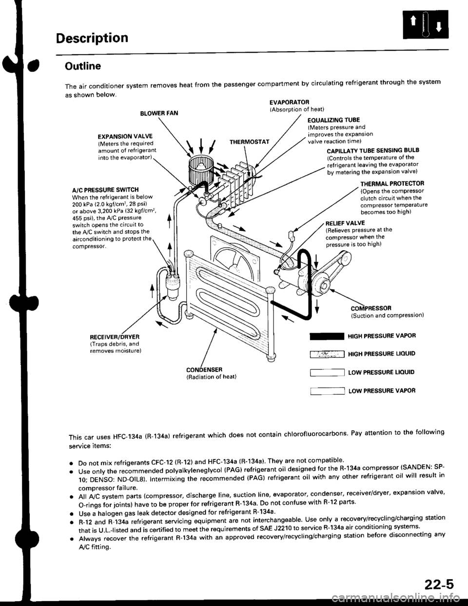
The air conditioner system removes heat from the passenger compartment by circulating refrigerant through the system
as shown below.
BLOWER FAN
EVAPORATOR(Absorption of heati
EOUALIZING TUBE(Meters pressure andimproves the expansionvalve reaction time)
into the evaporator)CAPILLATY TUBE SENSING BULB
lControls the temPerature of the
ref rigerant leaving the evaporator
by metering the expansion valve)
/\
THERMOSTAT
A/C PRESSURE SWITCH
When the refrigerant is below
200 kPa (2.0 kgtcm'�,28 Psi)or above 3,200 kPa 132 kgflcm',
455 psi), the Ay'C pressure
switch opens the circuit to
the A,/C switch and stops the
EXPANSION VALVE(Meters the requiredamount of refrigerant
airconditioning to Protect the
compressor.
RECEIVER/DRYER(Traps debris, andremoves morsturel
THERMAL PROTECTOR
{Opens the comPressorclutch circuit when the
compressor temPeraturebecomes too high)
RELIEF VALVE(Relieves pressure at the
compressor when thepressure is too high)
(Radiation of heat)
I
f-r-�-; I
(Suction and comPression,
HIGH PRESSURE VAPOR
HtGH PRESSUBE LIOUID
LOW PRESSURE LIOUID
This car uses HFC-134a (R-134a) refrigerant which does not contain chlorofluorocarbons Pay attention to the following
service items:
. Do not mix refrigerants CFC-12 (R-12) and HFC-134a (R-134a)' They are not compatible'
. Useonlythe recommended polyalkyieneglycol (PAG) refrigerant oil designedforthe R-134a compressor (SANDEN: SP-
10; DENSO: ND_OIL8). Intermixing ihe re-commended (pAG) refrigerant oil with any other refrigerant oil will result in
compressor failure.
. All A,,ic system parts {compressor, discharge line, suction line, evaporator, condenser, receiver/dryer, expansion valve'
O-rings for joints) have to be proper for refrigerant R- 134a Do not confuse with R-l2 parts'
. Use a halogen gas leak detector designed for refrigerant R-134a
. R-12 and R-134a refrigerant servacing equipment are not interchangeable. Use only a recovery/recycling/charging station
that is u,L.-listed and is certified to meet the requirements of sAE J2210 to service R-134a air conditioning systems'
. Always recover the refrigerant R-134a with an approved recovery/recycling/charging station before disconnecting any
A,/C fitting.
S]
22-5
Page 1450 of 2189
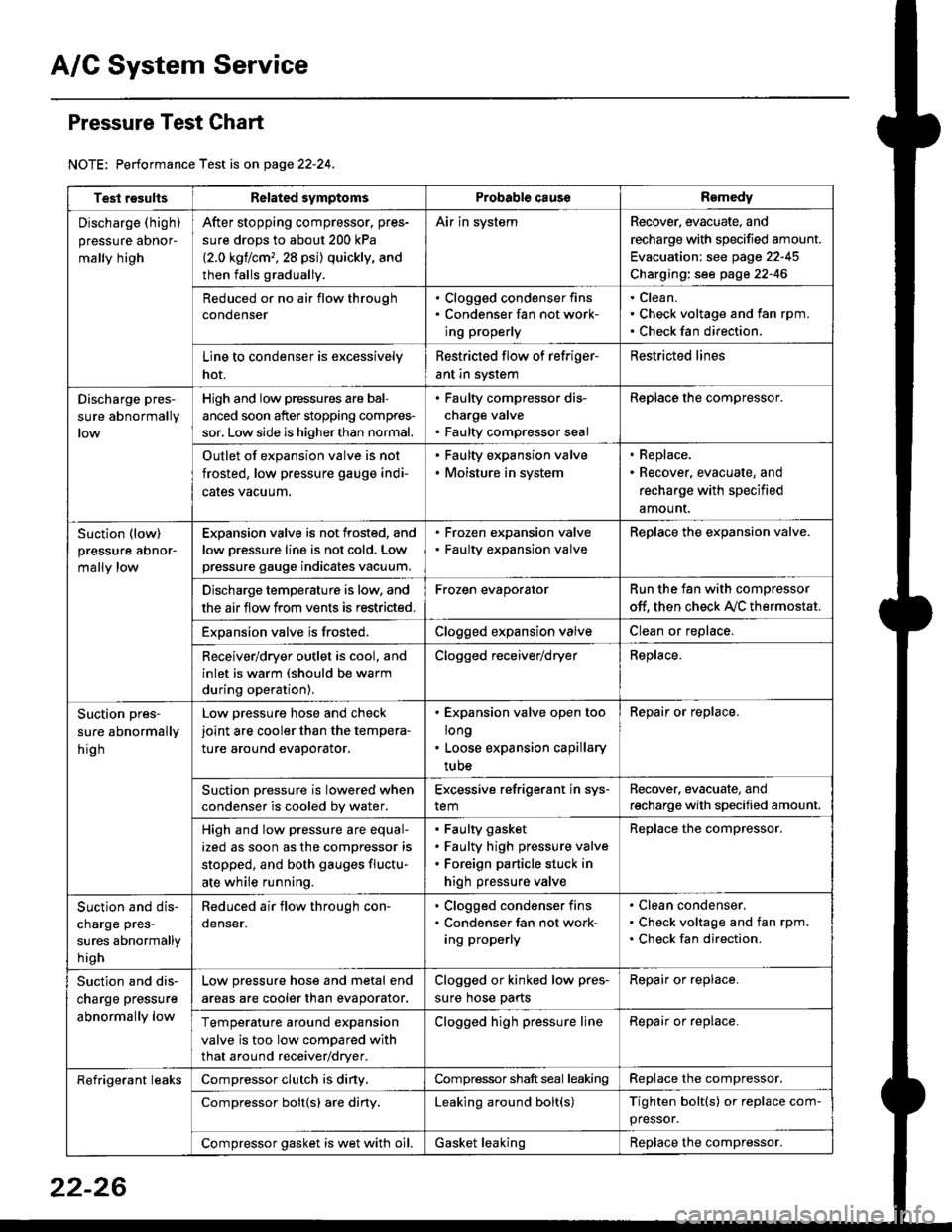
A/C System Service
Pressure Test Chart
NOTE: Performance Test is on page 22-24,
Test resultsRelated symptomsProbabl€ causeRemedy
Discharge (high)
pressure aDnor-
mally high
After stopping compressor. pres-
sure drops to about 200 kPa
{2.0 kgflcm,,28 psi) quickly, and
then falls gradually.
Air in systemRecover, evacuate, and
recharge with specified amount.
Evacuation: see page 22-45
Charging: see page 22-46
Reduced or no air flow through
condenser
. Clogged condenser fins. Condenser fan not work-
ing properly
Clean.
Check voltage and fan rpm.
Check fan direction.
Line to condenser is excessively
hot.
Restricted flow of refriger-
ant in system
Restricted lines
Discharge pres-
sure abnormally
High and low pressures are bal-
anced soon after stopping compres-
sor, Low side is higher than normal.
. Faulty compressor dis-
charge valve. Faulty compressor seal
Replace the compressor.
Outlet of expansion valve is not
frosted, low pressure gauge indi-
cales vacuum.
. Faulty expansion valve. Moisture in system
. Replace,. Recover, evacuate, and
recharge with specified
amount.
Suction (low)
pressure abnor-
mally low
Expansion valve is not frosted, and
low oressure line is not cold. Low
pressure gauge indicates vacuum.
. Frozen expansion valve. Faulty expansion valve
ReDlace the exoansion valve.
Discharge temperature is low. and
the air flow from vents is restricted.
Frozen evaporatorRun the fan with compressor
off. then check A,/C thermostat.
Exoansion valve is frosted.Clogged expansion valveClean or replace.
Receiver/dryer outlet is cool, and
inlet is warm (should be warm
during operation).
Clogged receiver/dryerReplace.
Suction pres-
sure abnormally
hig h
Low pressure hose and check
joint are cooler than the tempera-
ture around evaporator.
. Expansion valve open too
long. Loose expansion capillary
tube
Repair or replace.
Suction oressure is lowered when
condenser is cooled bv water.
Excessive refrigerant in sys-
tem
Recover. evacuate, and
recharge with specified amount.
High and low pressure are equal-
ized as soon as the compressor is
stopped, and both gauges fluctu-
ate while running.
Faulty gasket
Faulty high pressure valve
Foreign particle stuck in
high pressure valve
Replace the compressor.
Suction and dis-
charge pres-
sures abnormally
h igh
Reduced air flow through con-
denser.
. Clogged condenser fins. Condenser fan not work-
ing properly
Clean condenser.
Check voltage and fan rpm.
Check fan direction.
Suction and dis-
charge pressure
abnormally low
Low pressure hose and metal end
areas are cooler than evaporator.
Clogged or kinked low pres-
sure hose parts
Repair or replace.
Temperature around expansion
valve is too low compared with
that around receiver/dryer.
Clogged high pressure lineRepair or replace.
Refrigerant leaksCompressor clutch is diny,Compressor shaft seal leakingReplace the compressor.
Compressor bolt{s) are diny.Leaking around bolt(s)Tighten bolt(s) or replace com-
pressor.
Compressor gasket is wet with oil.Gasket leakingReplace the compressor.
22-26
Page 1466 of 2189
Compressor (DENSO)
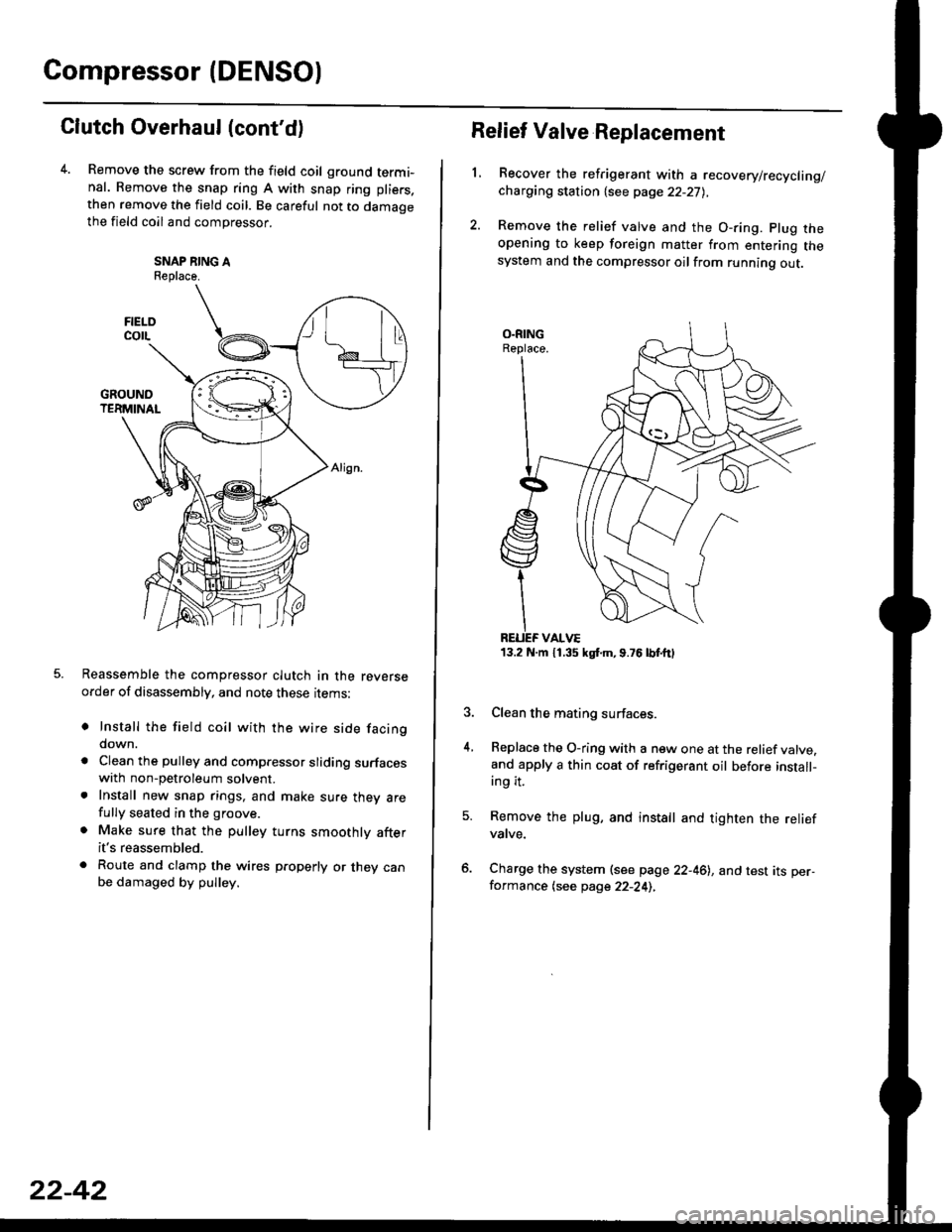
Clutch Overhaul (cont'd)
Remove the screw from the field coil ground termi-nal. Remove the snap ring A with snap ring pliers.
then remove the field coil. Be careful not to damaoethe field coil and compressor.
SNAP NING AReplace.
Reassemble the compressor clutch in the reverseorder of disassembly, and note these rrems:
o Install the field coil with the wire side facingdown.
a Clean the pulley and compressor sliding surfaceswith non-petroleum solvent.. Install new snap rings, and make sure thev arefully seated in the groove.
. Make sure that the pulley turns smoothly afterit's reassembled.
. Route and clamp the wires p.operly or they canbe damaged by pulley.
FIELOcorL
22-42
13.2 N.m 11.35 kgt m,9.76lbtttl
Relief Valve Replacement
L
4.
Recover the refrigerant with a recovery/recycling/charging station {see page 22-27),
Remove the relief valve and the O-ring. plug theopening to keep foreign matter from entering thesystem and the compressor oilfrom running out.
Clean the mating surfaces.
Replace the O-ring with a new one at the relief valve.and apply a thin coat of refrigerant oil before install-ing it.
Remove the plug, and install and tighten the reliefvatve.
Charge the system (see page 22-46), and test its per-formance (see page 22-24),
Page 1470 of 2189
A/C System Service
Charging
Use only service equipment that is U.L.-listed and is cer-
tified to meet the requirements of SAE J2210 to remove
HFC-134a (R-134a) from the air conditioner system.
CAUTION: Exposure to air conditioner refrigerant and
lubricant vapor or mist can irritale eyes, nose and
throat. Avoid breathing the air conditioner retrigerant
and lubricant vaoor or mist,
lf accidental system discharge occurs, ventilate workarea before resuming service, Additional health and
safety information may be obtained from the refrigerant
and lubricant manufacturers.
Refrigerant capacityt 600 - 650 g 121.1 - 22.9 ozl
CAUnON: Do not overcharg€ the system; the comprcssor
will be damaged.
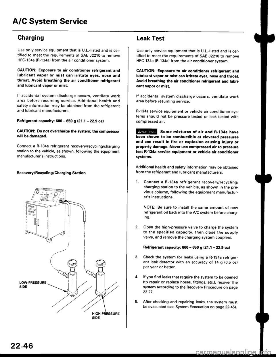
Connect a R-134a refrigerant recovery/recycling/charging
station to the vehicle, as shown, following the equipment
manufacturer's instructions.
Recovery/Recycling/Charging Station
22-46
Leak Test
Use only service equipment that is U.L,-listed and is cer-
tified to meet the requirements of SAE J2210 to remove
HFC-134a (R-134a) from the air conditioner system.
CAUTION: Exposure io air conditioner refrigerant and
lubricant vapot or mist can itritats eyes, no36 and thtoat.
Avoid breathing the air conditioner refrigeranl and lubri-
cant vapor or mist,
lf accidental system discharge occurs, ventilate workarea betore resuming service.
R-134a service equipment or vehicle air conditioner sys-
tems should not be pressure tested or leak tested with
comoressed air.
@ some mixtures of air and R-134a have
been shown to be combugtibls at elevatgd prossures
and can result in tire or explosion causing iniuly orplopgrty damage. Nev€r usc compre33od air to pressure
test R-13'la servica oquipment or yohiclo air conditionor
systems.
Additional health and safety information may be obtained
from the refrigerant and lubricant manufacturers.
1. Connect a R-134a refrigerant recove rylrecycling/
charging station to the vehicle, as shown in the pre-
vious column, following the equipment manufactur-
er's instructions.
NOTE; Be sure to install the same amount of new
refrigerant oil back into the A,/C system before charg-In9.
Open the high-pressure valve to charge the system
to the specified capacity, then close the supply
valve, and remove the charging system couplers.
Rofrigerant capacity: 600 - 650 g (21.1 - 22.9 oz)
Check the system for leaks using a R-134a refriger-
ant leak detector with an accuracy of 14 9 10.5 ozlper yea. or better.
lf you find leaks that require the system to be opened(to repair or replace hoses. fittings. etc.), recover the
system according to the Recovery Procedure on page
22-27.
After checking and repairing leaks. the system must
be evacuated (see System Evacuation on page 22-451.