Page 960 of 2189

Troubleshooting Flowchart - Secondary Gear Shaft Speed Sensor
NOTE: Record all freeze data before you troubleshoot
Po$ible Causo
. Oisconnectod secondarY gear
shaft speed sensor conn66or' short or open in secondary gear
shaft spe€d sensor wiro. Faulty secondarY gear 3haft
sPeed sensor
SECONDARY GEAR SHAFT
SPEEO SENSOR CONNECTOR
Terminal side of male terminals
PCM CONNECTOR D I15P)
VEL (WHT/REO) VEL SG IALK/WHTI
Wire side oI female terminals
(cont'd)
14-243
' OBD ll Scan Tool indicates
Code P1888.. Self-diagnosis E indicalor light
indicats Code 35.
Check the secondarY gear shaft
speed sensor installation, and
check it for damage.
ls the secondary gear shaft
speed sensor installedproperly, and not damaged?
Reinatall or replace and rocheck.
Measure SocondarY Gear Sh.ft
Speed Sen3or Resistance at the
Sensor Connector:1. Disconnect the 2P connector
trom the secondary gear shaft
speed sensor.2. Measure secondary gear shaft
speed sensor resistance at the
sensor connector.
ls the resistance 350 - 600 0?
Check SecondarY Gear Shaft
Speed Sensor lor a Short Circuit:
1. Disconned the D (16P) connec-
tor from the PCM.
2. Check for continuity between
body ground and the D1 ter-
minal and D7 terminal indi-
vidually.
Repair short in the wiros
b.tween the Dl and D7 termi_
ne13 and th€ secondarY geal
3haft lpeed sonsor.
To page 14-284
Page 965 of 2189
Electrical Troubleshooting ('99 - 00 Models)
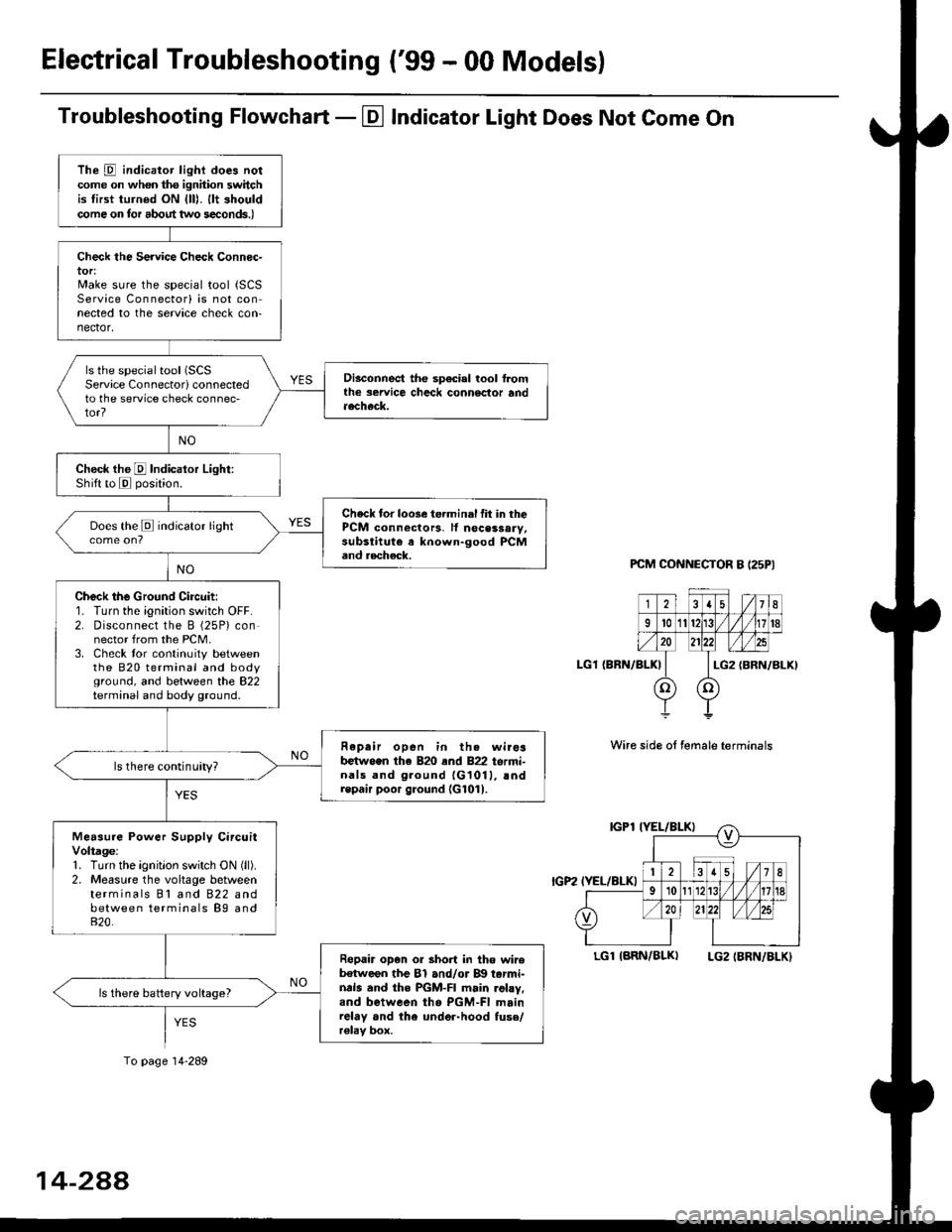
Troubleshooting Flowchart - El Indicator Light Does Not Come On
PCM CONNECTOR B I25PI
LGl {BRN/BLK)
Wire side ot female terminals
LGlIARN/BLK) LG2IBRN/BLKI
The D indicator light does notcome on whon ths ignhion switchis tirst turned ON {lll. llt shouldcome on tor about two s€conds.)
Check the Service Check Connec-tor:Make sure the special tool {SCSService Connectorl is not connected to the service check con-nector,
ls the special tool (SCS
Service Connectorl connectedto the service check connec-tor?
Disconnect the sp€cial tool f]omthe seruice chcck connoclor andaecheck.
Check the E Indicalor Light:Shift to E posjtion.
Check tor loose te.minal fit in thePCM connectors, lf nocessary,substitute a known-good PCMand aecheck.
Does the E indicator light
Check the Ground Circuit:1. Turn the ignition switch OFF.2. Disconnect the B (25P) connector from the PCM.3. Check tor continuity betweenthe 820 terminal and bodyground, and between the 822terminal and body ground.
Fepair open in th. wirosb€tw.en the 820 end 822 termi-nals and ground {G1011, !ndrepair poor ground {G1011.
ls there continuity?
Measure Power Supply CircuitVoltage:1. Turn the ignitlon switch ON (ll).
2. Measure the voltage betweenterminals Bl and 822 andbetween terminals B9 and820.
Ropair op€n or short in tho wireb€tween the Bl and/or B!| tarmi-nds and the PGM-FI main .ohy,and between tho PGM-FI mainrelay and the under-hood fuso/r€lav box.
ls there battery voltage?
To page 14-289
14-2AA
Page 966 of 2189
From page 14-289
Msaaure D IND Volt.ge:1. Turn the ignition switch OFF.
2. Connect tho B (25Plconnector
to the PCM.
3. Connect a digital multimeter
to the D14 and 820 or 822 ter-
mtnals.il. Turn the ignition switch ON(lll, and make sure that voltage
is available for two seconds
Check for open in the wire
between tha D14 terminal rnd
the gauge a33emblY. lf wiro ia
OK, chock for . frulty indicator
light bulb or a Iaulty gaug.
a3r6mbly printod circuit board.
Check D IND for a Short Circuit:
Check lor continuitY between the
D14 terminal and body ground.
Rgpair 3hort in the wire b.tween
the D14 tcrminal and tho gauge
a*somblY.
Check for loose terminsl fh in the
PCM connectors Check tho A/T
goar posilion switch. It neces'
saiy, iubstitute a known_good
PCM rnd rochock.
PCM CONNECTORS
D {16P1
(BRN/BI.X)D4 IND (GRN/BLK}
Wire side of female terminals
123rs 1/7I215
910nn fT /fl6l112
o lzlzz ,rl/zs 1311- -T---=4'+:l
LG2IBRN/BLKI\=/ |
r lz35
6i /l/t01112
l0
D' IND
o
IGRN/BLKI
4-289
Page 967 of 2189
ElectricalTroubleshooting ('gg - 00 Models)
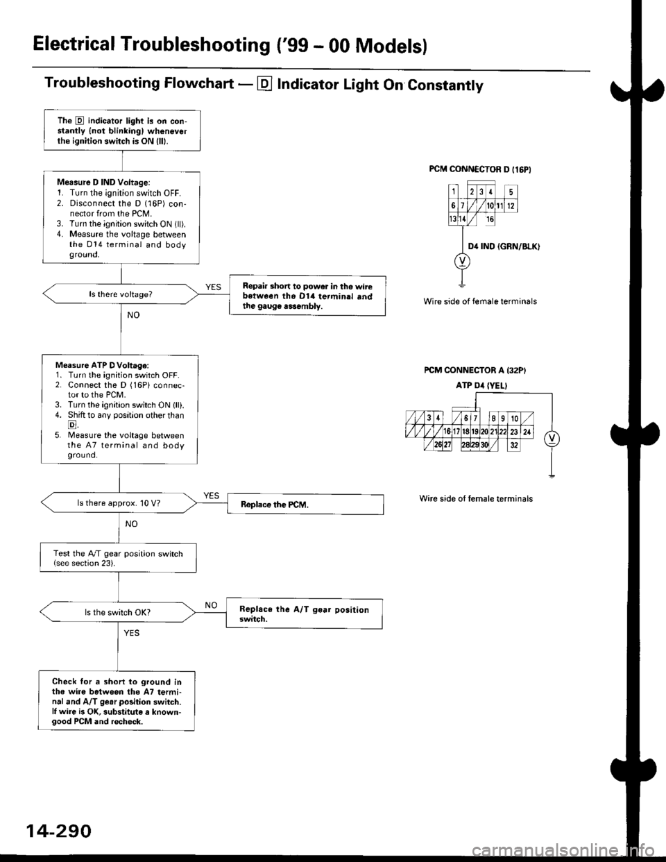
Troubleshooting Flowchart - E Indicator Light On Constantly
FCM CONNCCTOR D tl6PI
23I5
61t012
tsll / rc
II D4 rND
o
(GRN/BLK)
Wire side of female terminals
rcM CONNECTOR A I32PI
ATP Dil {YELI
Wire side of lemale terminals
The E indicator light is on con-stantly {not blinkingl wheneverthe ignition switch is ON lll|.
Mersure D IND Voltage:1. Turn the ignition switch OFF.2. Disconnect the D (16P) con-nector from the PCM.3. Turn the ignition switch ON (ll).4. Measure the voltage betweenthe 014 terminal and bodyground,
Repair short to power in tho wirebstween the Dl4 termin.l sndthe gaug€ r3sembly.
Measure ATP DVoltage:1. Turn the ignition switch OFF.2. Connect the D (16Pi connec-tor to the PCM.3. Turn the ignition switch ON lll).4. Shift to any position other thanE,5. lMeasure the voltage betweenthe 47 terminal and bodyground.
ls there approx. 10 V?
Test the A/T gear position switch{see section 23).
Check for a shorl lo ground inthe wire between tho A7 termi-nal and A/T ge.r polition switch.l, wire is OK, substitute a known-good PCM and recheck.
14-290
Page 1205 of 2189
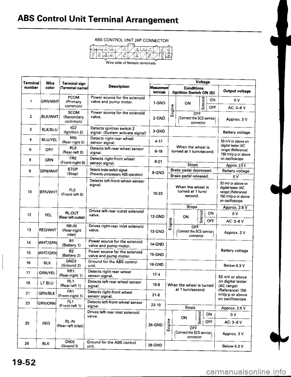
ABS Control Unit Terminal Arrangement
ABS CONTROL UNIT 26P CONNECTOR
Wire side of temale terminals
Terminalnumo0rWirecolorTerminal signTerminalnamoDgscriptionVoltage
Conditions(lgnition Switch ON flt))Output voltagoteminals
PCOM(Primary
common)
Power source for the solenoidvalve and pump motor.1-GNDON
=ONOV
AC: 3-6 V
BLK/WHTscoM(Secondary
common)
Power source for the solenoid
2.GNDOFF
lConnect the SCS service\
conneclor lApprox. 3 V
ELVBLUtG2(lgnition 2)Detects ignition switch 2
!9nal. (system activate signal)3-GNDBatt€ry voltage
BLU/YELRRO(Rear-right 0)Detects right-rear wheelsensor signal.4-17
When the wheel isturned at 1 turn/second.
53 mV or above ondigitaltester (ACra nge) {Fefera nce)150 mvp-p or aboveon oscilloscope
6GRYRLO(Rear-left 0)Detects left-rear wheel sensorsrgnal.6-19
8GRNFRO(Front-right 0)D€tects right-front wheelsgnsor srgnal,a-21StopsApprox.2.5VSTOP(Stop)hects brake switch signal.(Prevents unnecess€ry ABS operation)9-GNDBrake pedal depressed.Battery voltage
Brake pedal released.OV
10BRN^/vHTFLO(Front-left 0)
Detects left-front wheel sensorsignal.
10-23
When the wheel isturned at 1 turn/secono.
53 mV or above ondigitaltester (ACrange) (Referance)
150 mVFporaboveon oscilloscope
9!opsApprox. 2.5 V
12YELRLOUT(Rearjeft outlet)
Drives left-rear outlet solenoid
12.GNDON-9ONOV
OFFAC: 3^6 V
REDMHTRR]N(Rear-right
inlet)
Drives right-rear inlet solenoidvalve.13-GNDOFF
lconnect the SCS service]i connector IApprox. 3 V
14B1(Battery 1)Power source for the solenoidvatve and pump motor.14.GND
Battery voltage15WHT/G R N82(Baftery 2)Power source for the solenoidvarve ano pump motor.15.GND
r6BLKGND2{Ground 2)Ground for the ABS controlunit.16-GNDBelow 0.3 V
17GRN/'/ELRR1(Rear-right 1)Detects right-rear wheelsensor signal.17-4
When the wheel is turnedat 1 turn/second.
53 mV or aboveon digitaltester(AC range)(Referance) 150mVp-p or aboveon oscilloscope
19LT BLURLl(Rea.-left 1)Detects left-rear wheel sensorsagnal.19-6
GRN/BLKFRl(Front-right 1)Detects right-front wheelsensor signal.21-8
FL1(Front-left 1)Detects left-front wheel sensorsignal.23-10StopsApprox. 2.5 V
REDRL-IN(Rear-lett inletl
Drives left-r€ar inlet solenoid
25.GND
ut
ON
'6
-9ONOV
OFFAC: 3-6 V
OFF
lconnect the SCS service] connector lApprox. 3 V
BLKGND3(Ground 3)Ground for the ABS cgntrolunit.26.GNDBelow 0.3 V
19-52
Page 1206 of 2189
e\
t
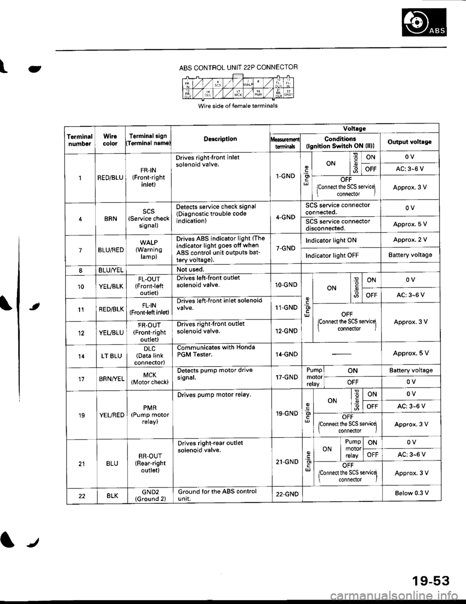
ABS CONTROL UNIT 22P CONNECTOR
Wire side of female terminals
TerminalnumbelWirocororTerminalsignDe3cription
Volt.ge
ConditionE(lgnition Switch ON (ll)lOutput voltagolTqrminal namslterminils
RED/BLUFR-IN{Front-rightinlet)
Drives right-front inletsolenoid valve.
I-GNDriJ
ON-9ONOV
OFFAC: 3-6 V
OFF
/Connect the SCS servicq
connector IApprox. 3 V
BRNscs(Service checksignal)
Detects service check signal
{Diagnostic trouble codeindication)4-GND
SCS service connectorconnected.OV
SCS service connectordisconneded.Appro)(. 5 V
7BLU/RED(Warning
ramp)
Drives ABS indicator light (The
indicator light go€s off when
ABS control unit outputs bat-
tery volta9e),
7-GND
Indicator light ONApprox, 2 V
Indicator light OFFBattery voltage
8BLU/YELNot used.
10YEUBLKFL.OUT{Front-leftoutlet)
Drives left-front outletsolenoid valve.10-GNOON
ONOV
OFFAC:3-6 V
11RED/BLKFLIN{Front-l€ft inlet)
Drives left-front inlet solenoid11-GNDOFF
lconnect the SCS servicq
connector IApprox. 3 V
YEUBLU
FR.OUT(Front-right
outlet)
Drives right-front outlet
solenoid valve.12-GNO
l4LT BLUDLC(Data linkconnector)
Communicates withPGM Tester.Honda14.GNDApprox. 5 V
17BRNA/ELMCK
lMotor check)
Detects pump motor drivesrgnal.17.GNDPumpmotorreray
ONBattery voltage
OFFOV
19YELREDPMR(Pump motorreray,
Drives pump motor relay.
19-GND
ONONOV
OFFAC: 3-6 V
OFFponnect the SCS sewicq
connedor lApprox. 3 V
BLURR-OUT(Rear-right
outletl
Drives right-rear outlel
solenoid valve.
21-GNDuJ
ON
Pumpmotorrelay
ONOV
OFFAC: 3-6 V
OFF
lconnect the SCS servicq
connedor )Approx. 3 V
22BLKGND2(Ground 2)Ground for the ABS controluntt.22-GNDBelow 0.3 v
19-53
Page 1213 of 2189
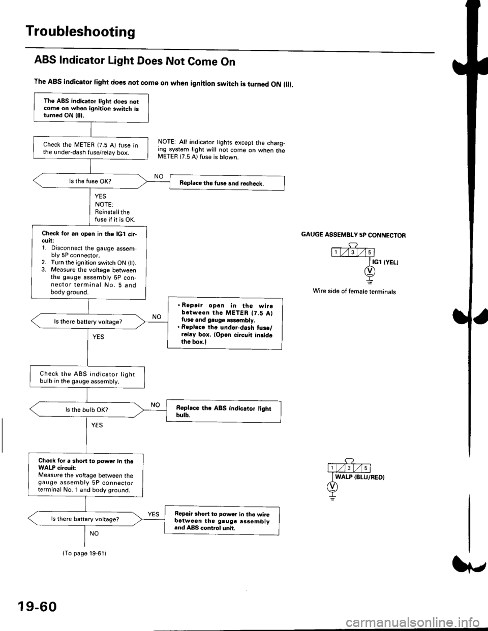
Troubleshooting
ABS Indicator Light Does Not Come On
YES
NOTE:Reinstallthefuse if it is OK.
The A8S indicator light does not come on when ignition switch is turned ON ll.
NOTE: All indicator tights except the charg,ing system light will not come on when theMETER 17.5 A) ft se is btown.
NO
GAUGE ASSEMBI"Y 5P CONNECTOR
Wire side of female terminals
Tho ABS indicator light does notcome on wh€n ignition switch istu.ned ON {lll.
check the METEB (7.5 A) fuse inthe under-dash fuse/relay box.
Beplace the tu3e and recheck.
Check for an open in th6 lcl cir-cuii:1, Disconnect the gauge assembly 5P connector.2. Turn the ignitjon switch ON l).3. Measure the voltage betweenthe gauge assembly 5P con-nector terminal No. 5 andbody ground.
. Ropair opan in tho wirobotwe€n thc METER t7.5 Attuso and gauge .$cmbly.. Roplacc th. und.r-dash tus./r.l.y box. lop.r cirouit in3idothe box.l
ls there baftery voltage?
Check the ABS indicator lightbulb in the gauge assembly.
ls the bulb OK?
Ch€ck tor a short to power in theWALP circuit:Measure the voltage between thegauge assembly 5P connectorterminal No. I and body ground.
Replir short to power in tho wiiGb.tweon the gruge rs3embly.nd ABS control unh.
ls there battery voltage?
lTo page 19-61)
19-60
Page 1214 of 2189
{From page 19.60)
Check the geuge a$embly:1. Turn the ignition switch OFF.
2. Connect the gauge assembly
5P connector.3. Connect the terminal No. 3 to
body ground with a iumper
4. Turn the ignition switch ON (ll).
Replace th€ ABS indicato. light
drive circuit in the gauge ai3om-
blY.
Does the ABS indicatorlight come on?
.Repair open in the wire
beiween the gauge assemblYand body ground.. Repair poor ground {G401,G402t.
Jt
GAUGE ASSEMBLY 5P CONNECTOR
,c? "l1t/'.lt/t5 |
JUMPER I GND IBLK}wrRE I-L
t
19-61