Page 1084 of 2189
Troubleshooting
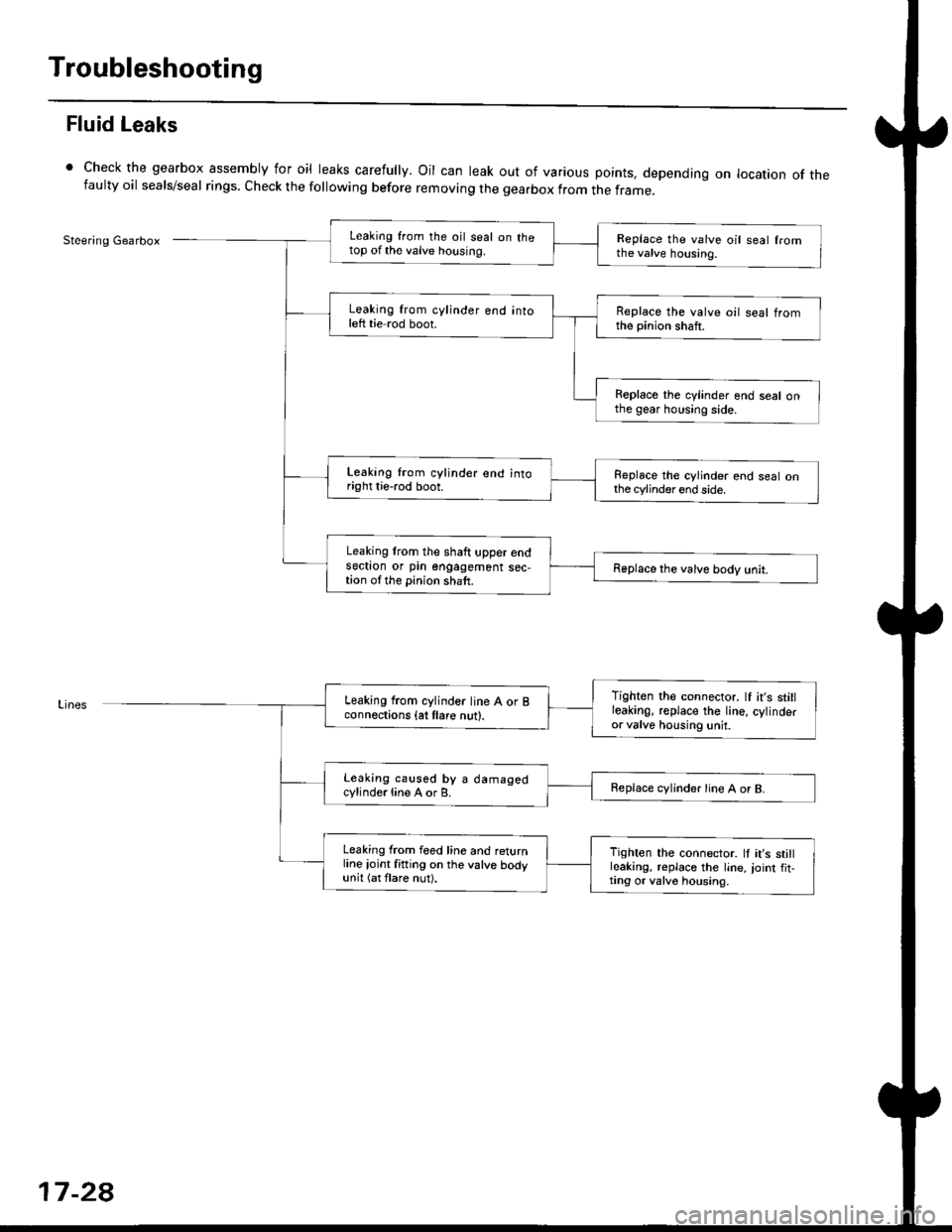
Fluid Leaks
Check the gearbox assembly for oil leaks carefully. Oil can leak out of various points. depending on location of thefaulty oil seals/seal rings. Check the following before removing the gearbox from the frame_
Steering GearboxLeaking from the oil seal on thetop of the valve housing.Replace the valve oil seal fromthe valve housing.
Leaking from cylinder end intoleft tie rod boot.Replace the valve oil seal tromthe pinion shaft.
Replace the cylinder end seal onthe gear housing side.
Leaking lrom cylinder end intoright tie-rod boot.Replace the cylinder end seal onthe cylinder end side.
Leaking lrom the shaft upper endsectron or pin engagement sec,tion ol the pinion shaft.Replace the valve body unit.
Tighten the connector. lf it's stillleakinO, replace the Iine, cylinderor valve housing unit.
Leaking from cylinder line A or Bconnections {at tlare nut}.
Leaking caused by a damagedcylinde.line A or B.Replace cvljnder line A or B.
Leaking from feed line and returnline ioint fitting on the valve bodyunit (at flare nut).
Tighten the connector. ll it's stillleaking, replace the line,,oint fit,ting or valv6 housing.
17-2a
Page 1085 of 2189
Pump outlet line(high pressure,
/
Pump inlet Iine(low-pressure)
Replace the housing O-rings
lf the housing still leaks, rePlace
the pumP.
Reservoir is overfilledPull off the hose and drain the
reservoit to the Proper level.
Air leak in suction side ofthe sys'
tem (reservoir, inlet hose, tront
pump seal).
Tighten the fifting. lI it's still leak-
ing, replace the O-ring or feed line.Leaking at the threaded fitting
Leaking at the swagged joint.
Leaking because ol damage, dete_
rioration, or imProPer assemblY.Reolace or rePair as necessarY.
tJ
17-29
Page 1089 of 2189
IRack Guide Adjustment
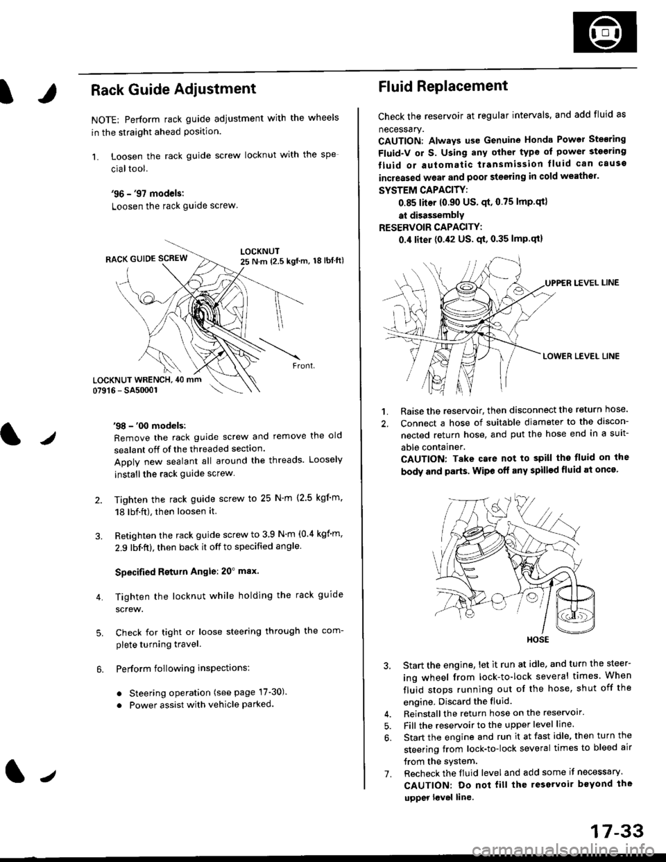
NOTE: Perform rack guide adjustment with the wheels
in the straight ahead Position.
1. Loosen the rack guide screw locknut with the
cialtool.
'96 - '97 models:
Loosen the rack guide screw
'98 - '00 models:
Remove the rack guide screw and remove the old
sealant off of the threaded section.
Apply new sealant all around the threads. Loosely
installthe rack guide screw
Tighten the rack guide screw to 25 N'm (2.5 kgf'm.
18 lbf.ft), then loosen it.
Retighten the rack guide screw to 3 9 N'm (0.4 kgim,
2.9 lbf.ft), then back it off to specified angle.
Specified Return Angle: 20" max.
Tighten the locknut while holding the rack guide
screw.
Check for tight or loose steering through the com-
plete turning travel.
Perform following insPections:
. Steering operation (see page 17-30).
. Power assist with vehicle parked.
4.
LOCKNUT WRENCH, 40 mm
lr
17-33
Fluid Replacement
Check the reservoir at regular intervals, and add fluid as
necessary.
CAUTION: Always us€ Genuine Honda Power Stearing
Fluid-V or S. Using any other type of power sto€ring
tluid or automatic transmission lluid can cause
increased wear and poor steering in cold weathor.
SYSTEM CAPACITY:
0.85 liter 10.90 US' qt,0.75 lmp'qt)
at disassembly
RESERVOIR CAPACITY:
0.4 liter (0.42 US. qt, 0.35 lmP.qt)
LEVEL LINE
LOWER LEVEL LINE
1. Raise the reservoir, then disconnect the return nose.
2. Connect a hose of suitable diameter to the discon-
nected return hose, and put the hose end in a suit-
able container.
CAUTION: Take care not to spill tho fluid on the
body and parts. Wipe off any spill€d fluid at oncs'
3. Start the engine, let it run at idle, and turn the steer-
ing wheel from lock-to-lock several times When
fluid stops running out of the hose, shut off the
engine, Discard the fluid.
4. Reinstall the return hose on the reservoir'
5. Fill the reservoir to the upper level line.
6. Start the engine and run it at fast idle, then turn the
steering trom lock-to-lock several times to bleed air
trom the system.
7. Recheck the fluid level and add some it necessary.
CAUTION: Do not fill the reservoir beYond the
upper l€vel line.
HOSE
Page 1095 of 2189
Power Steering Hoses, Lines
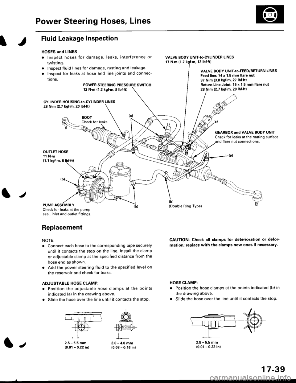
Fluid Leakage Inspection
HOSES and LINES
. Inspect hoses for damage, leaks, interference or
twisting.
. Inspect tluid lines for damage, rusting and leakage.
. Inspect for leaks at hose and line joints and connec-
tions.
POWER STEERINGswtTcH12 N.m {1.2 kgt.m,9lbt.ft}
CYLINDER HOUSING-to.CYLINDER LINES28 N.m (2.7 kgf.m, 20 lbf.ft)
VALVE BODY UNIT-to-CYLINDER LINES'17 N.m {1.712 tbl.ftl
VALVE BODY UNIT-Io-FEED/RETURN LINES
Feed line: 14 x '1.5 mm llare nut
37 N.m {3.8 kgJ.m, 27 lbf'tt)
Return Line Joint 16 x 1.5 mm flare nut
28 N m 12.7 kgf.m,20 lbtft)
HOSE CLAMP:
. Position the hose clamps at the points indicated (b) in
the drawing above.
. Slide the hose over the line until it contacts the stop.
8()07Check for leaks.
OUTLET HOSE11 N.m
G€AR8OX and VALVE BODY UNITCheck for leaks at the mating surfaceand flare nut connections,
tbt(Double Ring Typei
CAUTION: Check all clamps for deterioration or delor-
mation; replace with the clamps new ones il necessary.
(1.1 kgf.m,8
PUMP ASSEMBLYCheck for leaks at the pump
seal, inlet and outlet fiftings.
Replacement
NOTE:
. Connect each hose to the corresponding pipe securely
until it contacts the stop on the line. Install the clamp
or adiustable clamp at the specified distance from the
hose end as shown.
. Add the power steering fluid to the specified level on
the reservoir and check for leaks.
ADJUSTABLE HOSE CLAMP:
. Position the adiustable hose clamps at the points
indicated (a) in the drawing above.
. Slide the hose over the line until it contacts the stop.
2.5 - 5.5 mm{0.01 - 0.22 in)2.0 - 4.0 mm(0.08 - 0.16 in)
2.5 - 5.5 mm(0.01- 0.22 in)1.,
17-39
Page 1097 of 2189
Disassembly
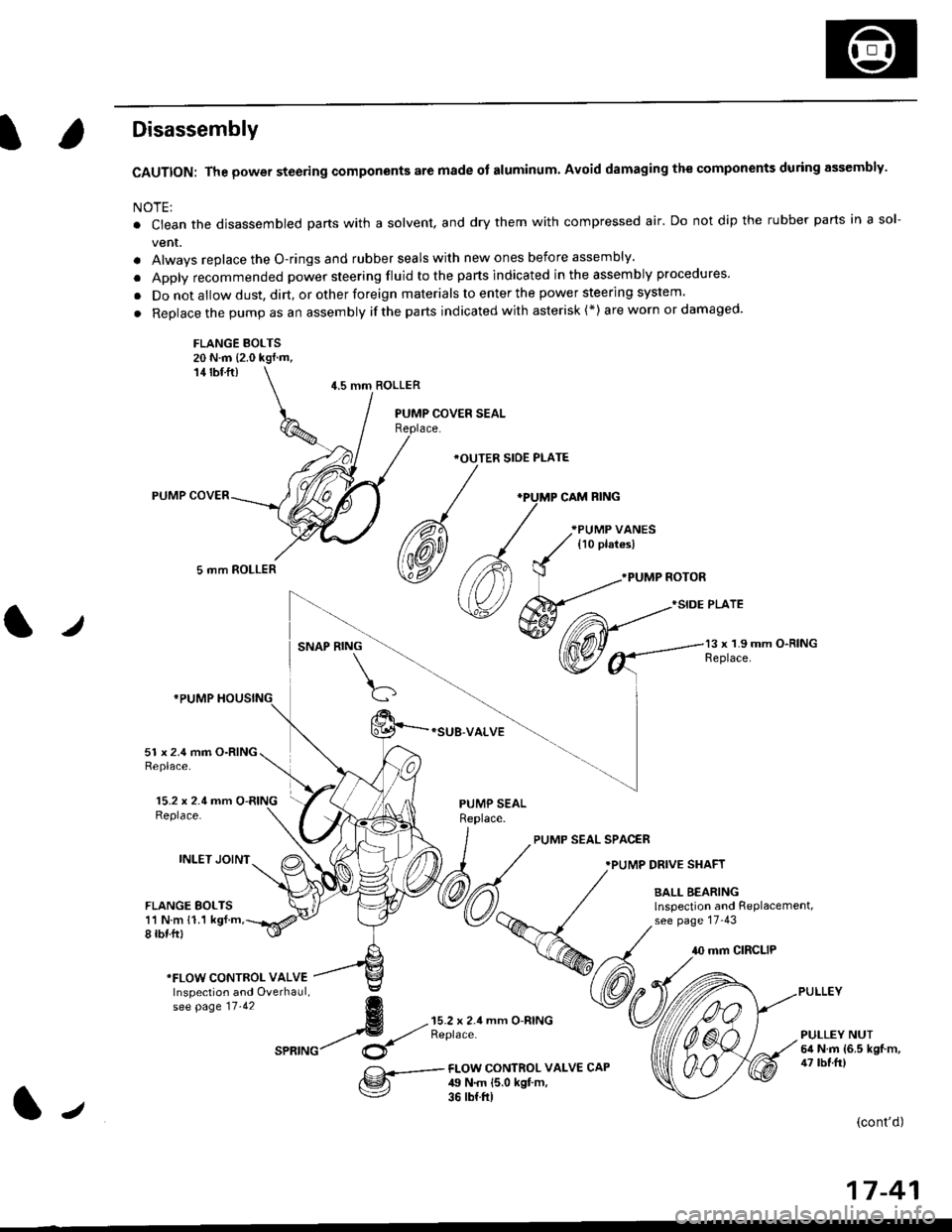
CAUTION: The power steering components are made of aluminum. Avoid damaging the components during assembly.
NOTE:
. Ctean the disassembled parts with a solvent, and dry them with compressed air. Do not dip the rubber parts in a sol-
vent.
. Alwavs replace the O-rings and rubber seals with new ones before assembly.
. Apply recommended power steering fluid to the parts indicated in the assembly procedures'
. Do not allow dust, dirt, or other foreign materials to enter the power steering system.
. Replace the pump as an assembly ifthe parts indicated with asterisk (*) are worn or damaged'
FLANGE BOLTS20 N.m {2.0 kgf.m,14 rbf ft)
5 mm ROLLER
4.5 mm ROLLER
*OUTER SIOE PLATE
*SUB-VALVE
.PUMP NOTOR
}SIDE PLATE
l,/SNAP RING13 x 1.9 mm O-RINGReplace.
15.2 x 2.4 mm O-RINGReplace.
INLET JOINT
51 x 2.4 mm O-RINGReplace.
FLANGE BOLTS11 N m 11.1 kgf.m,8 rbf.ftl
PUMP SEALReplace.
PUMP SEAL SPAC€R
.PUMP DRIVE SHAFT
BALL BEARINGlnspection and RePlacement,see page 17-43
10 mm CIRCLIP
*FLOW CONTROI- VALVEInspection and Overhaul,se[ pase tt.tz g
4 --{;'rX!;'seatuc/ $
mm O-RINGPULLEY NUT6il N.m {6.5 kgf.m,47 tbf.frlFI-OW CONTROL VALV€ CAP49 N.m {5.0 kgt m,36 rb{.ft)
(cont'd)
17-41
J
Page 1098 of 2189
Power Steering Pump
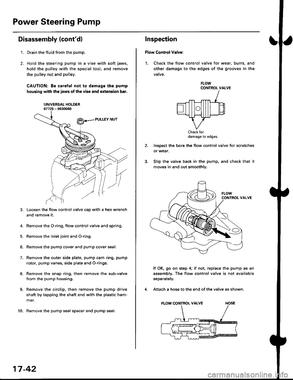
Disassembly (cont'dl
2.
't.Drain the fluid from the pump.
Hold the steering pump in a vise with soft jaws,
hold the pulley with the special tool, and remove
the pulley nut and pulley.
CAUTION: Be careful not to damage the pump
housing with the iaws of the vise and extension bar.
UNIVERSAL HOLDER
Loosen the flow control valve cap with a hex wrench
and remove it.
4. Remove the O-ring, flow control valve and spring.
5. Remove the inlet joint and O-ring.
6. Remove the pump cover and pump cover seal.
7. Remove the outer side plate, pump cam ring, pump
rotor, pump vanes, side plate and O-rings.
8. Remove the snap ring, then remove the sub-valve
from the pump housing.
9. Remove the circlip, then remove the pump drive
shaft by tapping the shaft end with the plastic ham-
mer.
10. Remove the pump seal spacer and pump seal.
17-42
Inspection
Flow Control Valve:
1. Check the tlow control valve for wear. burrs, and
other damage to the edges of the grooves in the
vatve,
FLOWCONTROL VALVE
Check fordamage to edges.
Inspect the bore the flow control valve for scratches
or wear.
Slip the valve back in the pump, and check that it
moves in and out smoothly.
lf OK, go on step 4; if not, replace the pump as an
assembly. The flow control valve is not available
separately.
Attach a hose to the end of the valve as shown.
FLOW CONTROL VALVE TIOSE
4.
Page 1100 of 2189
Power Steering Pump
Reassembly
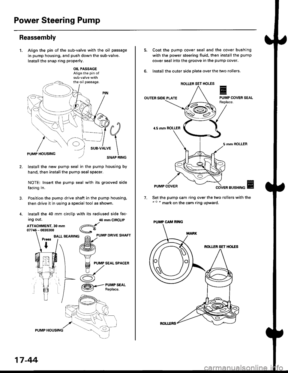
1.Align the pin of the sub-valve with the oil passage
in pump housing. and push down the sub-valve.
Installthe snap ring properly.
OIL PASSAGEAlign the pin of
the oil passage.
PUMP HOUSINGSNAP RING
Install the new pump seal in the pump housing by
hand, then installthe pump seal spacer.
NOTE: Insert the pump seal with its grooved side
facing in.
Position the pump drive shaft in the pump housing,
then drive it in using a special tool as shown.
Install the 40 mm circlip with its radiused side fac-
ing out,
ATTACHMENT, 30 mm
BALL BEARING
40 mm CIRCLIP
d
gf'uMP oRrvE sHAFr
/ffi\
f.\'vj
H PUMP SEAL SPACER
n,/
/:K
/ZA\.-- PUMP SEAL
V Reptace.
17 -44
ROLl.ERS
Coat the pump cover seal and the cover bushing
with the power steering fluid, then install the pump
cover seal into the groove in the pump cover.
lnstall the outer side olate over the two rollers.
ROL1IR
OUTER SIDE PLATE
4.5 mm ROLLER
5 mm ROLLER
PUMP COVERBUSHING
Set the pump cam ring over the two rollers with the" o " mark on the cam ring upward.
7.
ROI,IIR SET HO'"ES
PUMP CAM RING
Page 1104 of 2189
Steering Gearbox
Removal {cont'dl
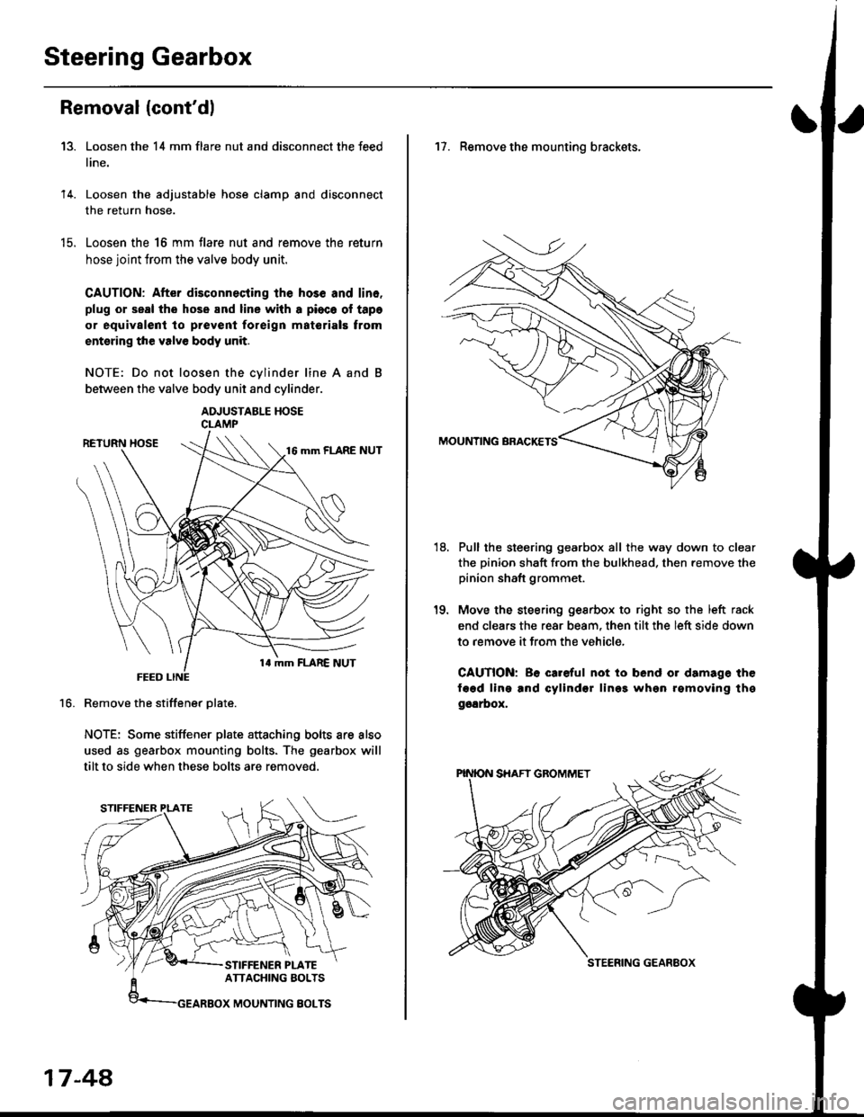
Loosen the 14 mm flare nut and disconnect the feed
line.
Loosen the adjustable hose clamp and disconnect
the return hose.
Loosen the 16 mm flare nut and remove the return
hose joint trom the valve body unit.
CAUTION: After disconnecting lhe hos6 and lin6.
plug or seal the hose and line with a pioca ol tapa
or equivalent to prevenl foreign matorials trom
entsring the valve body unit.
NOTE: Do not loosen the cvlinder line A and
between the valve body unit and cylinder.
ADJUSTABLE HOSECLAMP
Remove the stiffener Dlate.
NOTE: Some stiffener plate attaching bolts are also
used as gearbox mounting bolts. The gearbox will
tilt to side when these bolts are removed.
13.
14.
t9.
16.
17-48,
17. Remove the mounting brackets.
Pull the steering gearbox all the way down to clear
the pinion shaft from the bulkhead. then remove the
pinion shaft grommet.
Move the steering gesrbox to right so the left rack
end clears the rear beam, then tilt the left side down
to remove it from the vehicle,
CAUTION: Be careful not io bend or damage the
fagd ling and cylindsr lin99 whgn rgmoving thg
ggarbox,
18.
STEERING GEANEOX