Page 1187 of 2189
10. lnstall the special tool onto the spring cover, and
turn the shaft until the locknut contacts the plate.
Check that the flared end of the spring cover is below
the circlip groove.
Install the circlip into the groove. then remove the
special tool.
NOTE: Check that the circlip is seated in the groove
properly.
11.
12.
CIRCLIP
t.t
SPRING COVER
13. Coat a new piston seal with recommended silicone
grease in the caliper seal set, and install it in the cali-
per.
PISTON BOOTReplace. RUBBER GREASE
Apply recommended rubber grease in the caliper
seal set to the sealing lips and inside of a new pis-
ton boot, and install it in the caliper.
Coat the outside of the piston with brake fluid, and
install it onto the adjusting bolt while rotating it
clockwise with the tool.
CAUTION: Avoid damaging the piston and piston
boot.
PISTON SEALReplace.
-6l
14.
PISTON
(cont'd)
19-33
Page 1189 of 2189
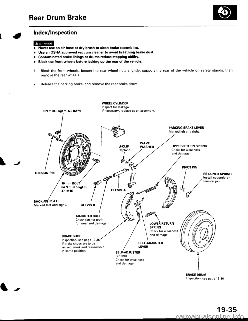
Rear Drum Brake
Index/lnspection
'1.
a
a
Never use an air hose or dly brush to clean brake assemblies,
Use an OSHA approved vacuum cleanar to avoid breathing brake dust,
Contaminated brake linings or drums reduce stopping ability.
Block the tront wheels before iacking up ths r€ar of lhe vehicle.
Block the front wheels, loosen the rear wheel nuts slightly, support the rear of the vehicle on safety stands, then
remove the rear wheels.
2. Release the parking brake, and remove the rear brake drum.
I N m 10.9 kgtm, 6.5 lbf.ftl
TENSION PIN
10 mm BOLT6,1N m 15.5 kgf m,47 tbf.ft)
WHEEL CYLINDERInspect for leakage.lf necessary, replace as an assembly.
u-cLrPReplace.
WAVEWASHER
PARKING BRAKE LEVERMarked left and right.
Check for weaknessano oamage,
UPPER RETURN SPRING
I
@JPIVOT PIN
BACKING PLATEMarked lelt and right-
/
€f-l.^
I I
*'t")
ctEv'sB
/ (t
/ ,.ro,".r r.*,"n
/ , Install securely on
| / tension pin.
d"/
IU
ADJUSTER BOI-TCheck ratchet teethfor wear and damage.LOWER RETURNSPRINGCheck for weaknessand oamage.BRAKE SHOEInspection, see page 19-36lf brake shoes are to bereused, mark and reassemblein same position.
SELF.ADJUSTERLEVEB
SELF-ADJUSTERSPRINGCheck for weaknessano oamage.
BRAKE DRUMInspection, see page '19 36
t
19-35
Page 1195 of 2189
Parking Brake Cable
LInspection and Replacement
CAUTION: The parking blake cables must not be bent or distorted. This will lead to stiff operation and premature cable
failure.
PARKING BRAKE CABLECheck for faulty movement.
PARKING BRAKE LEVERCheck for smoothoperation.
\i ,
EOUALIZER
PARKING BRAKE SWITCH
Disc Brake Type:
Disconnect the parking brake cable from the lever on the
caliper by removing the lock pin and clevis pin, and remove
the cable from the arm by removing the clip
CLEVIS PIN
Drum Brake Type:
Remove the parking brake cable from the backing plate
using a 12 mm offset wrench as shown.
12 mmOFFSET WRENCH(Commercially available)
DISC BRAKE TYPE:
CLEVIS PIN
PARKING ERAKE CABLE
{tt
BACKING PLATE
/
19-41
Page 1230 of 2189
l}tWheel Sensor Replacement
NOTE:
. Becareful when installingthe sensors to avoid twisting the wires.
. The torque value of the bolts is 9.8 N.m (1.0 kgf.m, 7 lbf.ft).
Front
FRONT WHEEL SENSOR
Rear
1. Remove the hub bearing unit (see section 18).
2. Remove the four backing plate bolts.
3, Pull the backing plate away from the trailing arm, then remove the wheel sensor. lt is not necessary to disconnect the
brake line.
NOTE: This illustration is drum brake type. The torque value of the disk type is same as drum type.
REAR WHEEL SENSOR
J\
It
19-77
Page 1261 of 2189
3
11.Thoroughly mix the adhesive and hardener together
on a glass or metal plate with a putty knife.
NOTE:
. Clean the plate with a sponge and alcohol before
mixing.
. Follow the instructions that come with the adhe-
stve.
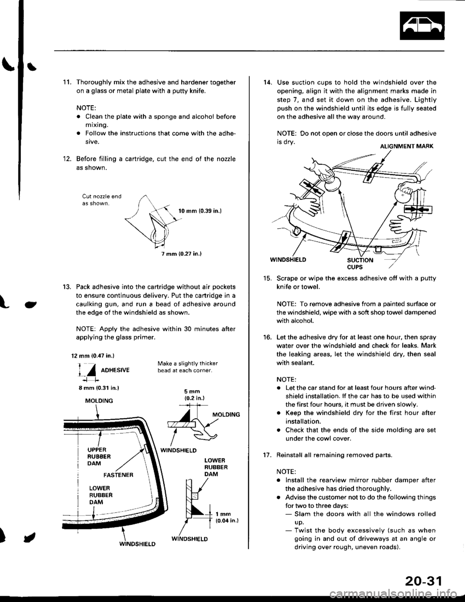
Before filling a cartridge. cut the end of the nozzle
as shown.
Cut nozzle end
tu
10 mm 10.39 in.)
7 mm (0.27 in.l
13. Pack adhesive into the cartridge without air pockets
to ensure continuous delivery. Put the cartridge in a
caulking gun, and run a bead of adhesive around
the edge of the windshield as shown.
NOTE: Apply the adhesive within 30 minutes after
applying the glass primer.
12 mm (0.47 in.)
l_Z oo*.t,ut
8 mm 10.31 in.l
UPPERRUBBERDAM
Make a slightly thickerbead at each corner.
5mm(0.2 in )='+
A\uloto^o. -.\
/wWINDSHIELD
LOWEBRUBBERDAM
lmm10.04 in.l
FASTENER
LOWERRUBBERDAM
)
MOLDING
WINDSHIELD
20-31
15.
16.
14. Use suction cups to hold the windshield over the
opening, align it with the alignment marks made in
step 7, and set it down on the adhesive. Lightly
push on the windshield until its edge is fully seated
on the adhesive all the way around.
NOTE: Do not open or close the doors until adhesive
ri vI Y ALTGNMENT MARK
Scrape or wipe the excess adhesive off with a putty
knife or towel.
NOTE: To remove adhesive from a painted surface or
the windshield, wipe with a soft shop towel dampened
with alcohol.
Let the adhesive dry for at least one hour, then spray
water over the windshield and check for leaks. Mark
the leaking areas, let the windshield dry, then seal
with sealant.
NOTE:
. Let the car stand for at least four hours after wind-
shield installation. lf the car has to be used within
the first four hours, it must be driven slowly.
. Keep the windshield dry for the first hour after
installation.
. Check that the ends of the side molding are set
under the cowl cover.
Reinstall all remaining removed parts.
NOTE:
. Install the rearview mirror rubber damper after
the adhesive has dried thoroughl',.
. Advise the customer not to do the following things
for two to three days:- Slam the doors with all the windows rolled
up.- Twist the body excessively (such as when
going in and out of driveways at an angle or
driving over rough, uneven roads).
't7.
Page 1265 of 2189
'11.Thoroughly mix the adhesive and hardener together
on a glass or metal plate wilh a putty knife.
NOTE:
. Clean the plate with a sponge and alcohol before
mixing.
. Follow the instructions that came with the adhe-
sive.
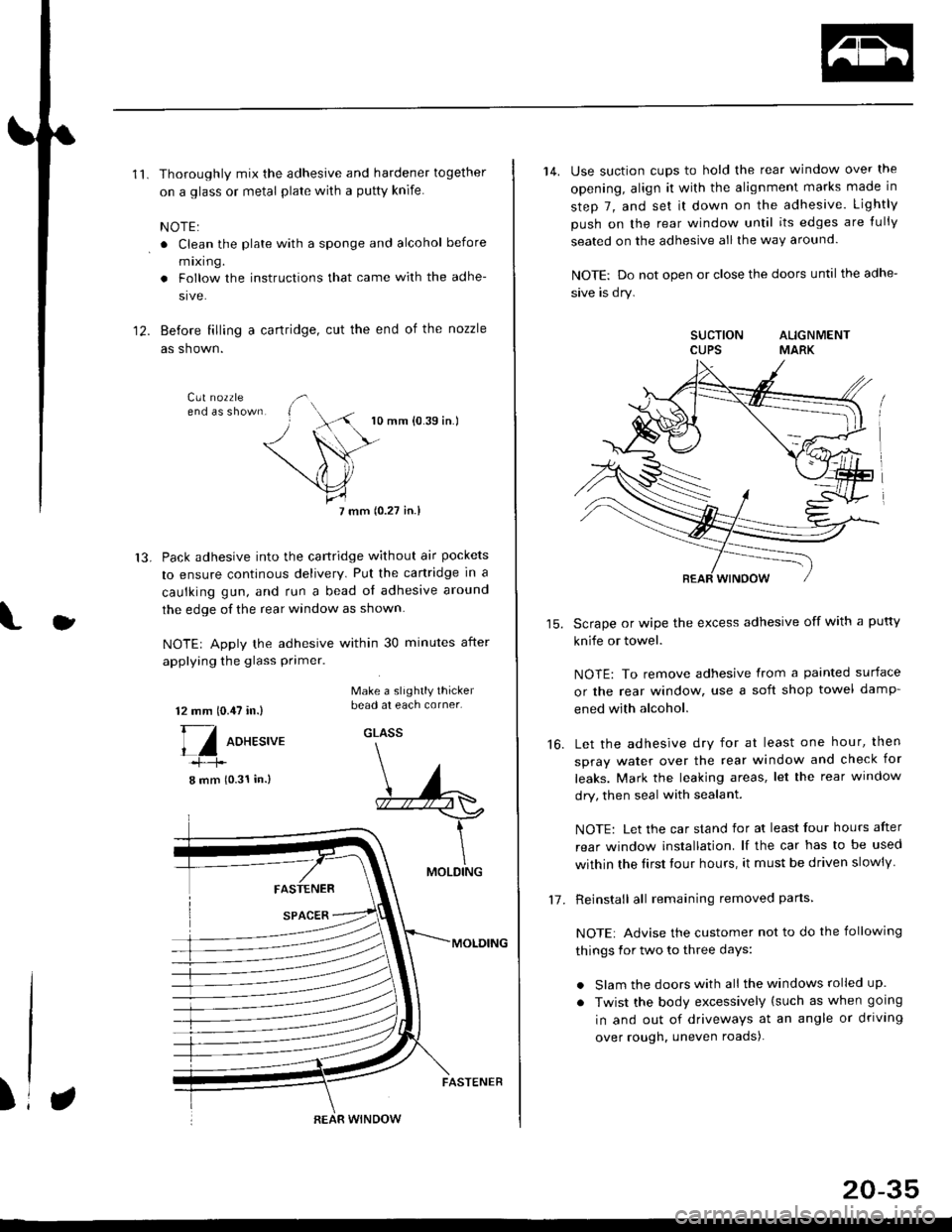
Before filling a cartridge, cut the end of the nozzle
as shown.
10 mm {0.39 in.)
7 mm (0.27 in.l
Pack adhesive into the cartridge without air pockets
to ensure continous delivery. Put the canridge in a
caulking gun, and run a bead ol adhesive around
the edge of the rear window as shown.
NOTE| Apply the adhesive within 30 minutes after
applying the glass primer.
12.
13.
J
12 mm 10.,U in.)
[/ oo*r.,u.
8 mm (0.31 in.)
Make a slightly thickerbead at each corner.
GLASS
FASTENER
SPACER
MOLDING
MOLDING
)REAR WINDOW
FASTENER
20-35
14. Use suction cups to hold the rear window over the
opening, align it with the alignment marks made in
step 7, and set it down on the adhesive. Lightly
push on the rear window until its edges are {ully
seated on the adhesive all the way around.
NOTE: Do not open or close the doors until the adhe-
sive is dry.
SUCTION ALIGNMENTCUPS MARK
Scrape or wipe the excess adhesive off with a putty
knife or towel.
NOTE: To remove adhesive from a painted surface
or the rear window, use a soft shop towel damp-
ened with alcohol.
Let the adhesive dry for at least one hour, then
spray water over the rear window and check for
leaks. Mark the leaking areas, let the rear window
dry, then seal with sealant.
NOTE: Let the car stand for at least four hours after
rear window installation. lf the car has to be used
within the Iirst tour hours, it must be driven slowly
Reinstall all remaining removed parts
NOTE: Advise the customer not to do the following
things for two to three days:
. Slam the doors with all the windows rolled up.
. Twist the body excessively (such as when going
in and out of driveways at an angle or driving
over rough. uneven roads).
16.
1-7 .
Page 1269 of 2189
3
t
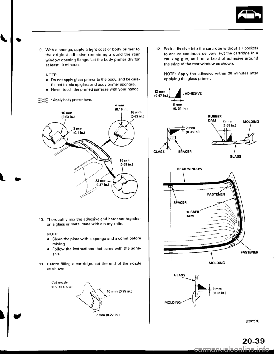
9. With a sponge, apply a light coat of body primer to
the original adhesive remaining around the rear
window opening flange. Let the body primer dry for
at least 10 minutes.
NOTE:
. Do not apply glass primer to the body, and be care-
ful not to mix up glass and body primer sponges.
. Never touch the primed surfaces with your hands.
//////// ' acoV boay primer here.
11.
Thoroughly mix the adhesive and hardener together
on a glass or metal plate with a putty knife.
NOTE:
. Clean the plate with a sponge and alcohol before
mlxlng.
. Follow the instructions that came with the adhe-
sive.
Before filling a cartridge, cut the end oJ the nozzle
as shown.
Cut nozzle
10.
I
10 mm {0.39 in.)
7 mm (0.27 in.)
12. Pack adhesive into the cartridge without air pockets
to ensure continuos delivery. Put the cartridge in a
caulking gun, and run a bead of adhesive around
the edge of the rear window as shown.
NOTE: Apply the adhesive within 30 minutes after
applying the glass primer.
ffi;fr'L/:ADHEs'�vE
8mm{0.31 in.l
GLASS
MOLDING
GLASS ,R1---$
f\+,,","
ffi-f to.oa in.t
-.17MoLD|NG / \
(cont'd)
20-39
Page 1273 of 2189
t
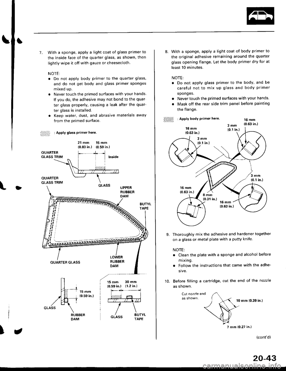
l
7. With a sponge, apply a light coat of glass primer to
the inside face of the quarter glass, as shown, then
lightly wipe it off with gauze or cheesecloth.
NOTE:
. Do not apply body primer to the quarter glass,
and do not get body and glass primer sponges
mixed up.
. Never touch the primed surfaces with your hands.
lf you do, the adhesive may not bond to the quar
ter glass properly, causing a leak after the quar-
ter glass is installed.
. Keep water, dust, and abrasive materials away
from the primed surface.
////////l : ^pptv stass primer he.e.
21 mm 15 mm
{0.83 in.) (0.59 in.)
UPPERRUBBERDAM
BUBBEBDAMOUARTER GLASS
15 mm10.59 in.l30 mm(r.2 in.)
)
8. With a sponge, apply a light coat of body primer to
the original adhesive remaining around the quarter
glass opening flange. Let the body primer dry for at
least 10 minutes.
NOTE:
. Do not apply glass primer lo the body, and be
careful not to mix up glass and body primer
sponges.
. Never touch the primed surfaces wilh your hands.
. Mask off the rear side trim panel before painting
the flange.
///////// | apetl body erimer he,e.16 mm{0.63 in.l
Thoroughly mix the adhesive and hardener together
on a glass or metal plate with a pufty knife.
NOTE:
. Clean the plate with a sponge and alcohol before
m rxlng.
. Follow the instructions that came with the adhe-
sive.
Before filling a cartridge, cut the end of the nozzle
as shown.
Cut nozzle end
10 mm (0.39 in.l
(cont'd)
9.
10.
7 mm (0.27 in.)
20-43