Page 1069 of 2189
)
lnstallation
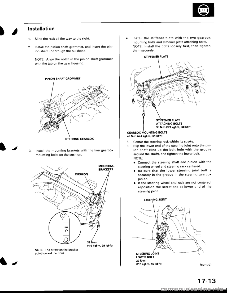
Slide the rack all the way to the righl
Install the pinion shaft grommet, and insert the pin
ion shaft up through the bulkhead.
NOTE| Align the notch in the pinion shaft grommet
with the tab on the gear housing.
1.
2.
J3. Install the mounting brackets with the two gearbox
mounting bolts on the cushion.
NOTE: The arrow on the bracketpoint toward the front.
STEEBING GEARBOX
{4.0 kgt.m,29 lbf.ftl
J
4. Install the stiffener plate with the two gearbox
mounting bolts and stiffener plate attaching bolts.
NOTEr Install the bolts loosely first. then tighten
them securely.
GEARBOX MOUNTING EOLTS43 N.m {4.4 kgf.m, 32 lbf'ftl
5. Center the steering rack within its stroke
6. Slip the lower end ot the steering joint onto the pin
ion shaft (line up the bolt hole with the groove
around the shaft), and tighten the lower bolt.
NOTE:
. Connect the steering shaft and pinion with the
steering wheel and steering rack centered
Be sure that the lower steering joint bolt is
securely in the groove in the steering gearbox
pin ion.
lf the steering wheel and rack are not centered,
reposition the serrations at lower end of the
steering ioint.
STEERING JOINT
STEERING JOINTLOWER BOLT22 N.m{2.2 kgf.m, 16lbf'ft}(cont'd)
I t- t5
STIFFENER PLATE
ATTACHING BOLTS38 N.m (3.9 kgf.m.28lbf.ftl
Page 1094 of 2189
Steering Column
Inspection
NOTE: The tilt steering column type is shown; the con-
ventional steering column is similar except for the tilt
mechantsm.
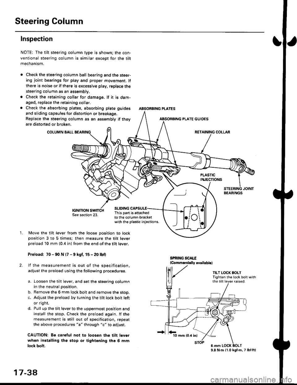
Check the steering column ball bearing and the steer-ing joint bearings for play and proper movement. lf
there is noise or if there is excessive play, replace the
steering column as an assembly.
Check the retaining collar for damage. lf it is dam-
aged, replace the retaining collar.
Check the absorbing plates, absorbing plate
and sliding capsules for distonion or breakage.
Replace the steering column as an assembly
are distorted or broken.
COLUMN BALL
ABSORBING PLATE GUIDES
guides
if they
SLIDING
BEARINGS
TILT LOCK BOLTTighten the lock bolt withthe tilt lever raised.
This part is attachodto the column bracketwith the plastic injections.
1.Move the tilt lever from the loose position to lockposition 3 to 5 times; then measure the tilt leverpreload l0 mm {0.4 in) from the end ofthe tilt lever.
Preload: 70 - 90 N (7 - 9 kgf. 15 - 20 lbf)
lf the measurement is out of the specification,
adjust the pfeload using the following procedures.
a. Loosen the tilt lever, and set the steering column
in the neutral position.
b. Remove the 6 mm lock bolt and remove the stop.
c. Adjust the preload by turning the tilt lock bolt left
or flgnr.
d. Pull up the tilt lever to the uppermost position and
install the stop. Check the preload again. lf the
measurement is still out of specification, repeat
the above procedures "a" through "c" to adjust.
CAUTION: Be caretul not to loosen tho tilt lever
when installing the stop or tightening the 6 mm
lock bolt.
17 3a
10 mm (0.4 inl
9.8 N.m (1.0 kgl.m,7 lbf.ft)
Page 1097 of 2189
Disassembly
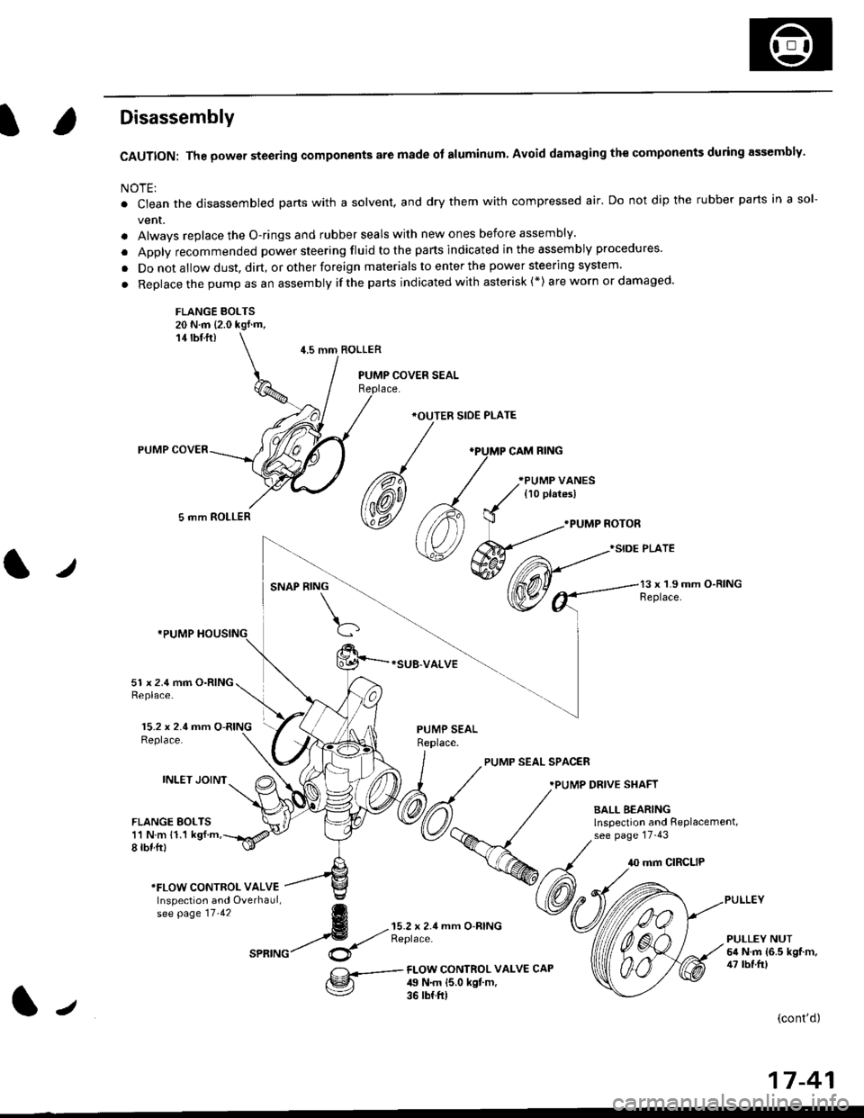
CAUTION: The power steering components are made of aluminum. Avoid damaging the components during assembly.
NOTE:
. Ctean the disassembled parts with a solvent, and dry them with compressed air. Do not dip the rubber parts in a sol-
vent.
. Alwavs replace the O-rings and rubber seals with new ones before assembly.
. Apply recommended power steering fluid to the parts indicated in the assembly procedures'
. Do not allow dust, dirt, or other foreign materials to enter the power steering system.
. Replace the pump as an assembly ifthe parts indicated with asterisk (*) are worn or damaged'
FLANGE BOLTS20 N.m {2.0 kgf.m,14 rbf ft)
5 mm ROLLER
4.5 mm ROLLER
*OUTER SIOE PLATE
*SUB-VALVE
.PUMP NOTOR
}SIDE PLATE
l,/SNAP RING13 x 1.9 mm O-RINGReplace.
15.2 x 2.4 mm O-RINGReplace.
INLET JOINT
51 x 2.4 mm O-RINGReplace.
FLANGE BOLTS11 N m 11.1 kgf.m,8 rbf.ftl
PUMP SEALReplace.
PUMP SEAL SPAC€R
.PUMP DRIVE SHAFT
BALL BEARINGlnspection and RePlacement,see page 17-43
10 mm CIRCLIP
*FLOW CONTROI- VALVEInspection and Overhaul,se[ pase tt.tz g
4 --{;'rX!;'seatuc/ $
mm O-RINGPULLEY NUT6il N.m {6.5 kgf.m,47 tbf.frlFI-OW CONTROL VALV€ CAP49 N.m {5.0 kgt m,36 rb{.ft)
(cont'd)
17-41
J
Page 1098 of 2189
Power Steering Pump
Disassembly (cont'dl
2.
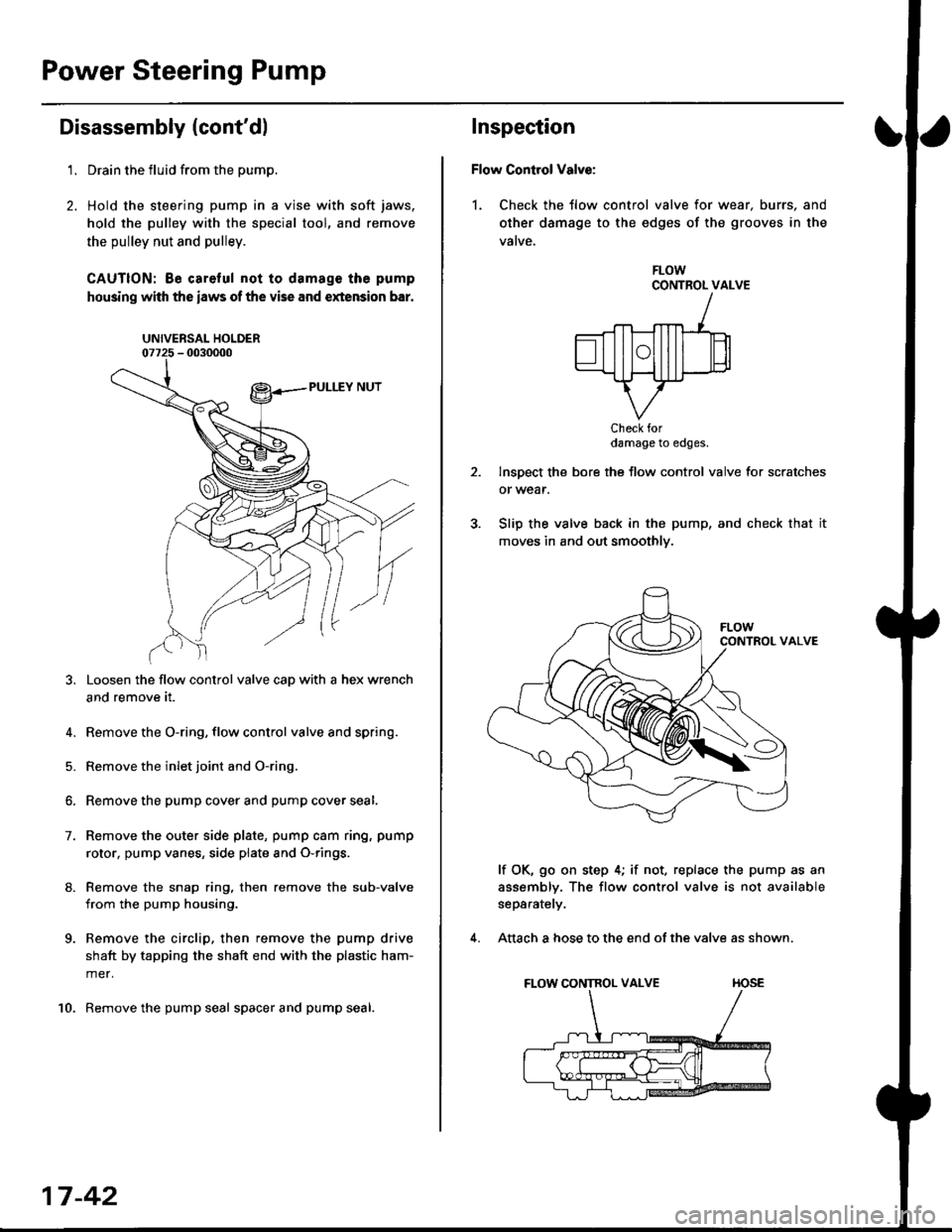
't.Drain the fluid from the pump.
Hold the steering pump in a vise with soft jaws,
hold the pulley with the special tool, and remove
the pulley nut and pulley.
CAUTION: Be careful not to damage the pump
housing with the iaws of the vise and extension bar.
UNIVERSAL HOLDER
Loosen the flow control valve cap with a hex wrench
and remove it.
4. Remove the O-ring, flow control valve and spring.
5. Remove the inlet joint and O-ring.
6. Remove the pump cover and pump cover seal.
7. Remove the outer side plate, pump cam ring, pump
rotor, pump vanes, side plate and O-rings.
8. Remove the snap ring, then remove the sub-valve
from the pump housing.
9. Remove the circlip, then remove the pump drive
shaft by tapping the shaft end with the plastic ham-
mer.
10. Remove the pump seal spacer and pump seal.
17-42
Inspection
Flow Control Valve:
1. Check the tlow control valve for wear. burrs, and
other damage to the edges of the grooves in the
vatve,
FLOWCONTROL VALVE
Check fordamage to edges.
Inspect the bore the flow control valve for scratches
or wear.
Slip the valve back in the pump, and check that it
moves in and out smoothly.
lf OK, go on step 4; if not, replace the pump as an
assembly. The flow control valve is not available
separately.
Attach a hose to the end of the valve as shown.
FLOW CONTROL VALVE TIOSE
4.
Page 1100 of 2189
Power Steering Pump
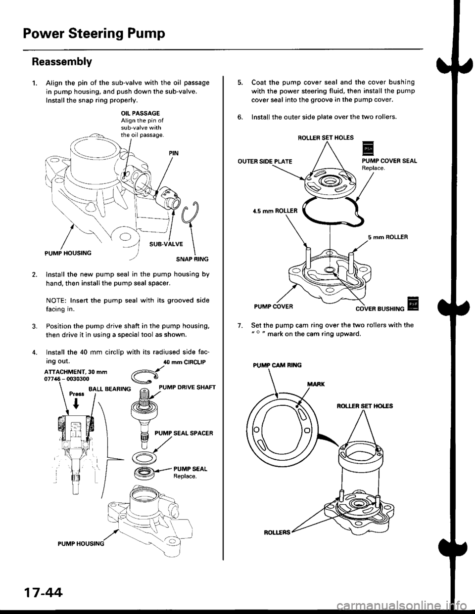
Reassembly
1.Align the pin of the sub-valve with the oil passage
in pump housing. and push down the sub-valve.
Installthe snap ring properly.
OIL PASSAGEAlign the pin of
the oil passage.
PUMP HOUSINGSNAP RING
Install the new pump seal in the pump housing by
hand, then installthe pump seal spacer.
NOTE: Insert the pump seal with its grooved side
facing in.
Position the pump drive shaft in the pump housing,
then drive it in using a special tool as shown.
Install the 40 mm circlip with its radiused side fac-
ing out,
ATTACHMENT, 30 mm
BALL BEARING
40 mm CIRCLIP
d
gf'uMP oRrvE sHAFr
/ffi\
f.\'vj
H PUMP SEAL SPACER
n,/
/:K
/ZA\.-- PUMP SEAL
V Reptace.
17 -44
ROLl.ERS
Coat the pump cover seal and the cover bushing
with the power steering fluid, then install the pump
cover seal into the groove in the pump cover.
lnstall the outer side olate over the two rollers.
ROL1IR
OUTER SIDE PLATE
4.5 mm ROLLER
5 mm ROLLER
PUMP COVERBUSHING
Set the pump cam ring over the two rollers with the" o " mark on the cam ring upward.
7.
ROI,IIR SET HO'"ES
PUMP CAM RING
Page 1101 of 2189
I
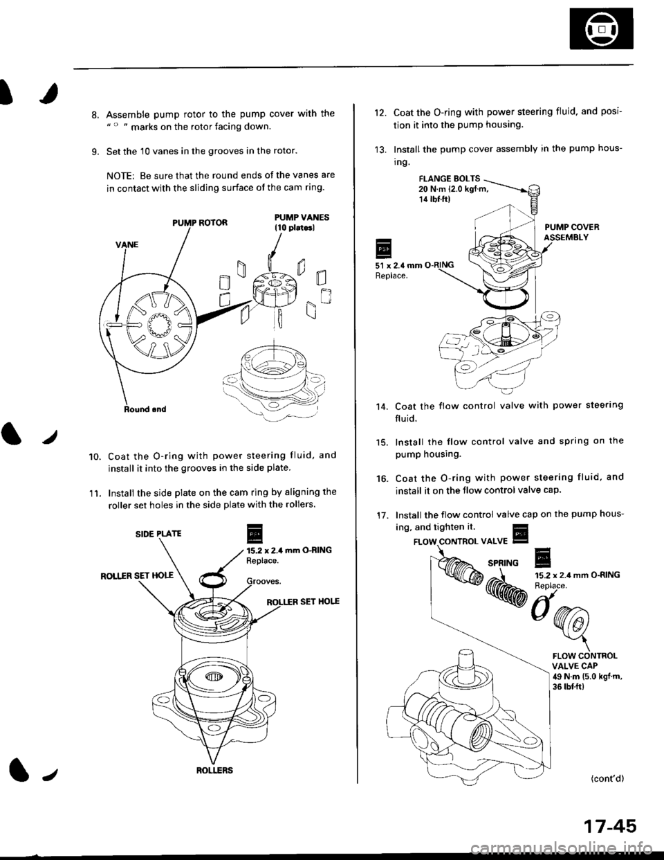
8.
9.
Assemble pump rotor to the pump cover with the" " " marks on the rotor facing down.
Set the 10 vanes in the grooves in the rotor.
NOTE: Be sure that the round ends ot the vanes are
in contact with the sliding surface of the cam ring.
Coat the O-ring with power steering fluid, and
install it into the grooves in the side plate.
Install the side plate on the cam ring by aligning the
roller set holes in the side plate with the rollers.
mm O-RING
ROLIIR SET HOTT
SET HOI.^E
0E
gn
10.
11.
r
E15.2 x 2,1Replace.
PUMP ROTOR
SIDE PLATE
ROI.I.ERSl,
't2.Coat the O-ring with power steering fluid. and posi
tion it into the pump housing.
Install the pump cover assembly in the pump hous-
tng.
FI.ANGE EOLTS20 N.m (2.0 kgf.m,14 tbf.ft)
PUMP COVERASSEMBLY
51 x 2.4 mmReplace.
Coat the flow control valve with power steerlng
fluid.
15. lnstall the flow control valve and spring on the
pump housing.
Coat the O-ring with power steering fluid, and
install it on the Jlow control valve cap.
Install the flow control valve cap on the pump hous-
't 4.
16.
17.
ing, and tighten it.
{cont'd)
17-45
FLOW CONTROLVALVE CAP49 N.m (5.0 kgj m,
36 tbf.ft)
Page 1104 of 2189
Steering Gearbox
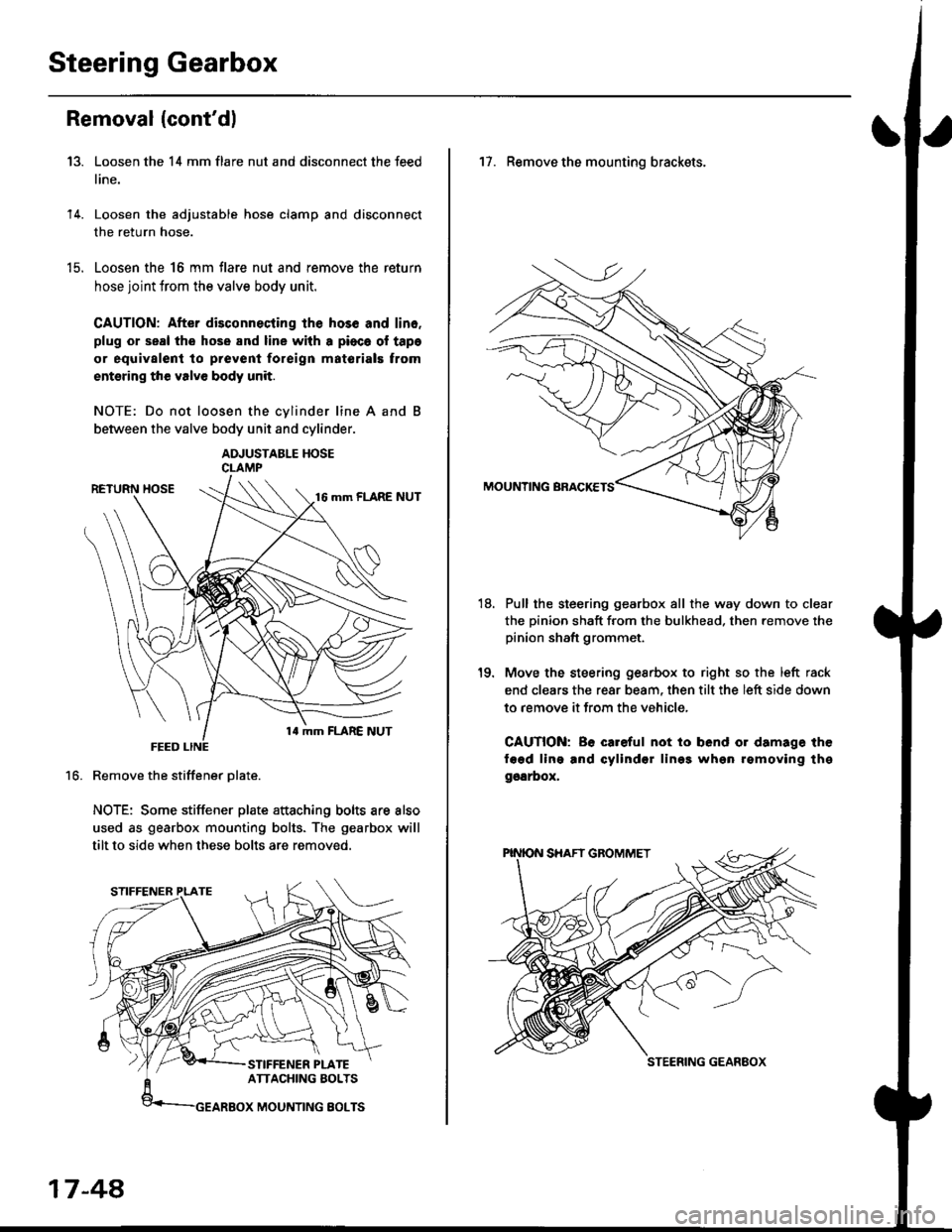
Removal {cont'dl
Loosen the 14 mm flare nut and disconnect the feed
line.
Loosen the adjustable hose clamp and disconnect
the return hose.
Loosen the 16 mm flare nut and remove the return
hose joint trom the valve body unit.
CAUTION: After disconnecting lhe hos6 and lin6.
plug or seal the hose and line with a pioca ol tapa
or equivalent to prevenl foreign matorials trom
entsring the valve body unit.
NOTE: Do not loosen the cvlinder line A and
between the valve body unit and cylinder.
ADJUSTABLE HOSECLAMP
Remove the stiffener Dlate.
NOTE: Some stiffener plate attaching bolts are also
used as gearbox mounting bolts. The gearbox will
tilt to side when these bolts are removed.
13.
14.
t9.
16.
17-48,
17. Remove the mounting brackets.
Pull the steering gearbox all the way down to clear
the pinion shaft from the bulkhead. then remove the
pinion shaft grommet.
Move the steering gesrbox to right so the left rack
end clears the rear beam, then tilt the left side down
to remove it from the vehicle,
CAUTION: Be careful not io bend or damage the
fagd ling and cylindsr lin99 whgn rgmoving thg
ggarbox,
18.
STEERING GEANEOX
Page 1122 of 2189
Steering Gearbox
Installation (cont'dl
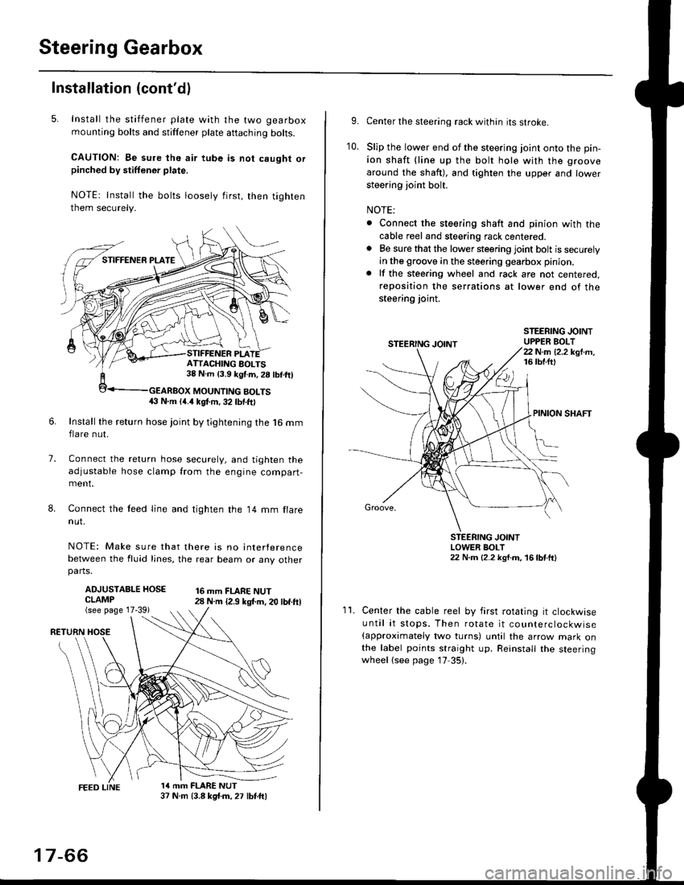
5. Install the stiffener plate with the two gearbox
mounting bolts and stiffener plate aftaching bolts.
CAUTION: Be sure the air tube is not caught orpinched by stiffener plate,
NOTE: Install the bolts loosely first, then tighten
them securely.
7.
8.
6.Install the return hose joint by tightening the l6 mm
flare nut.
Connect the relurn hose securely, and tighten the
adjustable hose clamp from the engine compart-ment.
Connect the feed line and tighten the 14 mm flare
nut.
NOTE: Make sure that there is no interference
between the fluid lines, the rear beam or any otherparts.
ADJUSTABLE HOSECLAMP(see page 17-39)
16 mm FLARE NUT28 N.m {2.9 ksl.m. 20 lbf.ft)
RETURN
1a mm FLARE NUT37 N.m (3.8 kg{.m, 27 lbt.ftl
ATTACHING AOLTS38 N.m 13.9 kgf.m, 28 lbf.ftl
MOUNTING BOLTS(} N.m (4.a kgt m, 32 lbf.ftl
17-66
9.Center the steering rack within its stroke.
Slip the lower end of the steering joint onto the pin-
ion shaft (line up the bolt hole with the groove
around the shaft), and tighten the upper and lower
steering joint bolt.
NOTE:
. Connect the steering shaft and pinion with the
cable reel and steering rack centered.. Be sure that the lower steering joint bolt is securely
in the groove in the steering gearbox pinion.
. lf the steering wheel and rack are not centered,
reposition the serrations at lower end of the
steering joint.
10.
STEERING JOINTUPPER BOLT22 N.m (2.2 kgf.m,16 tbt.ftl
PINION SHAFT
Groove,
STEERING JOINTLOWER BOLT22 N.m (2.2 kgt.m, 16lbtttl
11.Center the cable reel by first rotating it clockwise
until it stops. Then rotate it counterclockwise(approximately two turns) until the arrow mark onthe label points straight up. Reinstall the steeringwheel (see page 17 35).