Page 1371 of 2189

Seat Belts
Child Seat Anchor Plate Removal/lnstallation
2DllDl
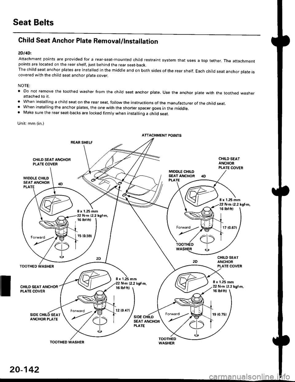
Attachment points are provided for a rear-seal-mounted child restraint system that usespoints are located on the rear shelf, tust behind the rear seat-back.The child seat anchor plates are installed in the middle and on both sides of the rear shelf.covered with the child seat anchor olate cover.
a top tether. The attachment
Each child seat anchor plate is
NOTE:
' Do not remove the toothed washer from the child seat anchor plate, Use the anchor plate with the toothed washerattached to it.
. When installing a child seat on the rear seat, follow the instructions of the manufacturer of the child seat.. When installing the anchor plates, the one with the shoner spacer goes in the middle.. Make sure the rear seat-backs are locked firmly when installing a child seat.
Unit: mm (in.)
REAR SHELF
CIIILD SEAT ANCHORPLATE COVER
MIDOLE CHILDSEAT ANCHOR
CHILO SEATANCHORPLATE COVER
CHILD SEATANCHORPLATE COVER
8 x 1.25 mm22 N.m 12.2 kgl m,
PLA
8 x 1.25 mm22 N.m 12.2 kgl.m,
I x 1.25 mm22 N.m 12.2 kgl.m,16 tbt.ftt
17 {0.67)
16 tbf.ft)
15 {0.s9)
WASHER
rl)
.t
TOOTHEO
ll ff*,".rd,',i"'"o*
SIDESEAT
I x 1,25 mmN.m {2.2 kgf.m.16 tbtftl
SIDE
16 tbf ftl
ANCHOR PLATESEAT ANCHORPLATE
ATTACHMENT POINTS
torward .
20-142
TOOTHED
12lO.47l19 (0.75)
Page 1372 of 2189
3D:
Attachment points are provided for a rear-seat mounted child restraint system that uses a top tether' The attachment
points are located on the rear trim panel.
The child seat anchor plates are rnstalled in the middle and on both sides of the rear trim panel Each child seat anchor
plale is covered with the child seat anchor plate cover'
NOTE:
. Do not remove the toothed washer from the child seat anchor plate. use the anchor plate with the toothed washer
attached to it.
. when installing a child seat on the rear seat, follow the instructions ol the manufacturer of the child seat'
. Make sure the rear seat-backs are locked firmly when installing a child seat'
gn;1 6rn (in.)
ATTACHMENT POINTS
CHILO SEATANCHOR PLATE
CHILD SEATANCHOB PLATECOVER
8 x 1.25 mm22 N..n (2.2 kgl'm.16 tbfft)
;x?',rff{-*.
20-143
Page 1456 of 2189
Gompressor (SANDEN)
lllustrated Index
CENTER NUTReplace.
<-- ARMATURE PLATElnspection, page 22-33
SNAP RING BReplace.
ROTOR PULLEYInspection, page 22-33
SNAP RING AReplace.
FIELD COILlnspection, page 22-33
sHrM(s)Replace.
COMPRESSoR ](Do not disassembte ) ---------------->l
Replacement. page 22,36
THERMAL PROTECTORReplace.Inspection, page 22-33Replacement, page 22-36
tv
i-
22-32
Page 1457 of 2189

Clutch InsPection
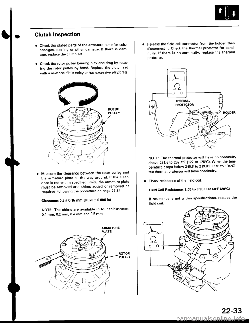
Check the plated parts of the armature plate for color
changes, peeling or other damage lf there is dam-
age. replace the clutch set.
Check the rotor pulley bearing play and drag by rotat-
ing the rotor pulley by hand Replace the clutch set
with a new one if it is noisy or has excessive play/drag
Measure the clearance between the rotor pulley and
the armature plate all the way around lf the clear-
ance is not within specified limits, the armature plate
must be removed and shims added or removed as
required, following the procedure on page 22-34
Cl€arance: 0.5 ! 0.15 mm {0.020 t 0.006 in)
NOTE: The shims are available in four thicknesses:
0.1 mm,0.2 mm,0.4 mm and 0.5 mm
. Release the field coil connector from the holder' then
disconnect it. Check the thermal protector for conti-
nuity. lf there is no continuity. replace the thermal
protecror,
NOTE: The thermal protector will have no continuity
above 251.6 to 262.4oF 1122lo 128'C). When the tem-
perature drops below 240 8 to 219.8"F (116 to 104"C),
the thermal protector will have continuity
. Check resistance of the field coil
Field Coil Resistance: 3.05 to 3.35 O at 68"F (20"C)
lf resistance is not within specifications, replace the
field coil.
22-33
Page 1458 of 2189
Compressor {SANDEN)
Clutch Overhaul
1. Remove the center nut while holding the armatureplate with the tool.
CENTER NUT17.6 N.m {1.8 kg{.m,'t3 tbnft}
2. Remove the armature plate by pulling it up by hand.
ARMATURE PLATE
A/C CLUTCH HOLDER{Commerciallv aveilable)Robinair: P/N 10204Kent-Moore: P/N J37872
22-34
3. Remove snap ring B with snap ring pliers.
NOTE:
. Be careful not to damage the rotor pulley and
compressor during removal/installation.. Once snap ring B is removed, replace it with anew one.
A
\/
G::.
Remove the rotor pulley from the shaft with a puller
and the special tool.
NOTE: Place the claws of the puller on the back of
the rotor pulley, not on the belt area; otherwise the
rotor pulley can be damaged.
. r \:g2rl -/ /
.-!L;j'/
TWO JAW PULLER{Commercially
Page 1463 of 2189
lllustrated Index
).-
CENTER BOLT
PBESSURE PLATE
Inspection, Page 22 40
sHrM(s)
SNAP RING B
Replace.
PULLEYInspection, Page 22'40
SNAP RING A
Replace.
FIELD COILInspection, page 22 40
SUCTION SERVICE VALVE
RELIEF VALVEReplacement, page 22'42
22-39
Page 1464 of 2189
Compressor (DENSOI
Clutch Inspection
Check the plated parts of the pressure plate for colo.changes, peeling or other damage. lf there is dam-age, replace the clutch set.
Check the pulley bearing play and drag by rotatingthe pulley by hand, Replace the clutch set with a newone if it is noisy or has excessive play/drag.
Measure the clearance between the pullev and thepressure plate all the way around. lf the clearance isnot within specified limits, the pressure plate must beremoved and shim(s) added or removed as required,
following the procedure on page 22-41.
Clearanca:0.5 t 0.15 mm {0.020 r 0.006 in}
NOTE: The shims are availabte in three thicknesses:0.1 mm,0.3 mm and 0.5 mm.
22-40
. Check resistance of the field coil. lf resistance is notwithin specifications, replace the field coil.
Fiald Coil Resistanc€: 3.it to 3.8 O at 20.C l68.Fl
Page 1465 of 2189
Clutch Overhaul
1. Remove the center bolt while holding the pressure
olate with the sPecialtool.
CENTER BOLT13.2 N.m (1.35 ksl m, 9.?6 lbf'ft)
A/C CLUTCH HOLOER(Commercially available)
Robinair: P/N 10204
Kent-Moore: P/N J37872
Remove the pressure plate and shim(s). taking care
not to lose the shim{sl.
PAESSUREPLATE
3. Remove the snap ring B with snap ring pliers, then
remove the pulley Be careful not to damage the
pulley and comPressor'
SNAP RING B
Replace.
'.L-)
.'l 5$ f-t
1/---( ll l,
vll/
(cont'd)
22-41