Page 1824 of 2189
Connector Views
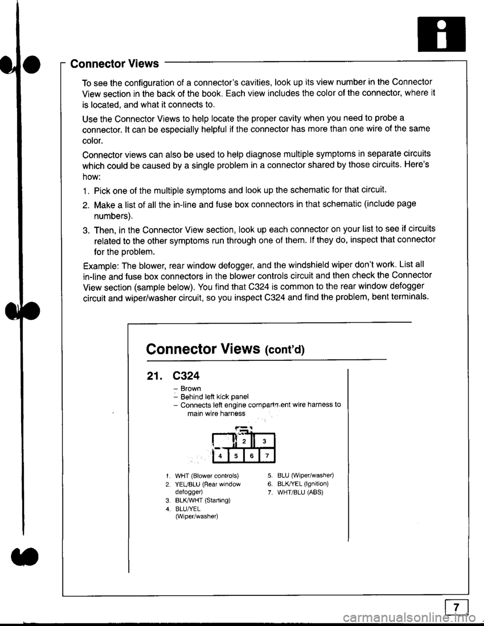
To see the configuration of a connector's cavities, look up its view number in the Connector
View section in the back of the book. Each view includes the color of the connector, where it
is located, and what it connects to.
Use the Connector Views to help locate the proper cavity when you need to probe a
connector. lt can be especially helpful if the connector has more than one wire of the same
cotor.
Connector views can also be used to help diagnose multiple symptoms in separate circuits
which could be caused by a single problem in a connector shared by those circuits. Here's
how:
1. Pick one of the multiple symptoms and look up the schematic for that circuit.
2. Make a list of all the in-line and fuse box connectors in that schematic (include page
numbers).
3. Then, in the Connector View section, look up each connector on your list to see il circuits
related to the other symptoms run through one of them. lf they do, inspect that connector
for the oroblem.
Example: The blower, rear window defogger, and the windshield wiper don't work. List all
in-line and fuse box connectors in the blower controls circuit and then check the Connector
View section (sample below). You find that C324 is common to the rear window defogger
circuit and wiper/washer circuit, so you inspect C324 and find the problem, bent terminals.
5.
6.
7.
1.
2.
WHT (Blower controls)
YEUBLU (Rear window
defogger)
BLK,ryVHT (Starting)
BLU/YEL(Wiper/washe0
8LU (Wiper/washed
BLfiEL (lgnition)
WHT/BLU (ABS)
Connector Views (cont'd)
21. C324
Brown
Behind left kick panel- Connects left engine compartry'ent wire harness to
main wire harness
ll,ll,
567
Page 1826 of 2189
Connectors - "C"
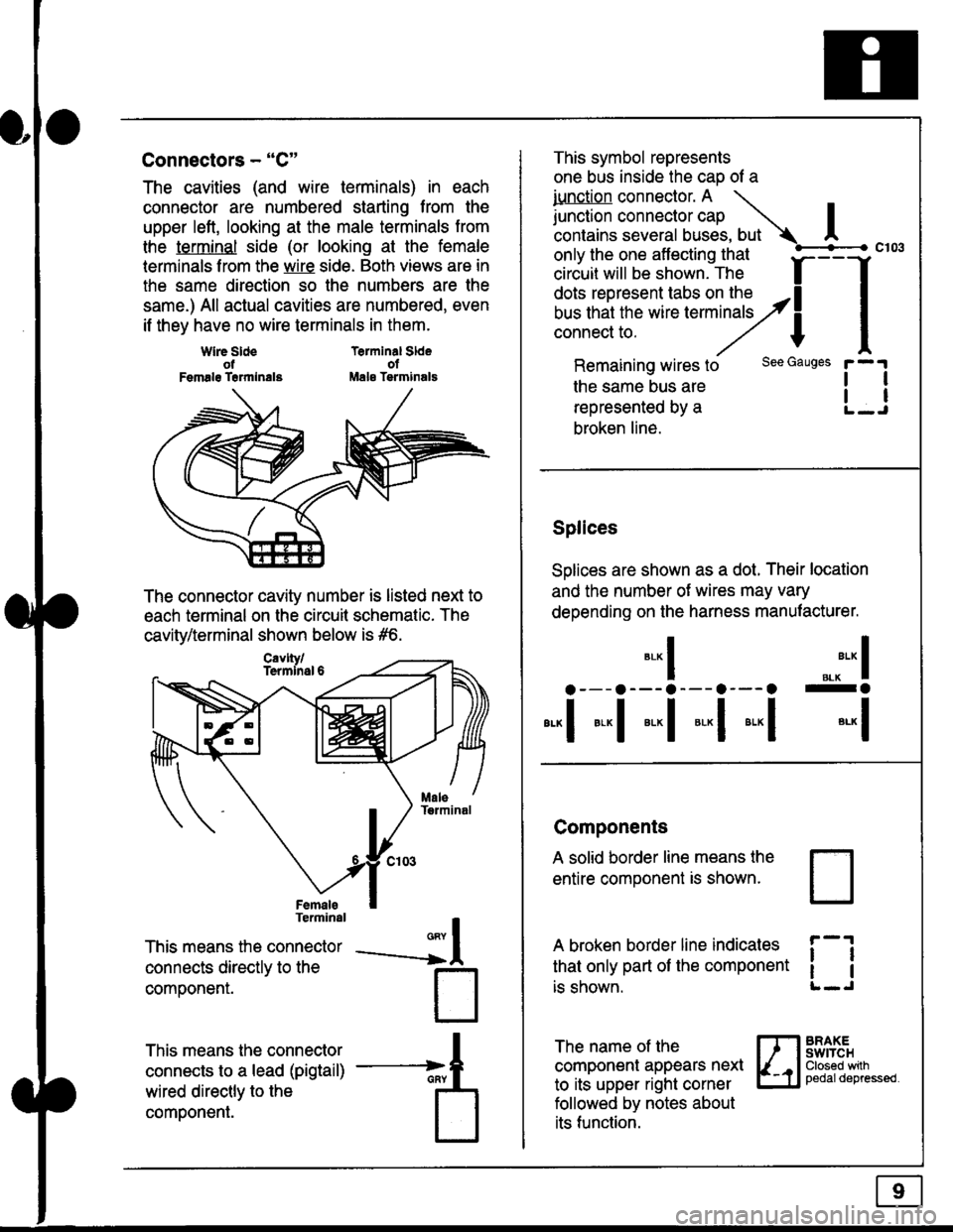
The cavities (and wire terminals) in each
connector are numbered starting from the
upper left, looking at the male terminals trom
the terminal side (or looking at the female
lerminals f rom the wire side. Both views are in
the same direction so the numbers are the
same.) All actual cavities are numbered, even
if they have no wire terminals in them.
Terminal SldeolMale Tsrminals
{
T
_A
Wlre SldeotFemalg Trrmlnala
The connector cavity number is listed next to
each terminal on the circuit schematic. The
cavity/terminal shown below is #6.
Terminal
This means the connector
connects directly to the
componenr.
This means the connector
connects to a lead (pigtail)
wired directly to the
component.
Cavlty/Termlnsl 6
only the one affecting that
ciriuit will be shown. The f
--f
!!*!"*F"#fi5'�;,Hy4
I
Remaining wires to
the same bus are
represented by a
broken line.
The name of the
component appears next
to its upper right corner
followed by notes about
its function.
This symbol represents
one bus inside the cao of a
iunction connector. A \
lr"ctb. connectorcap |contains several buses, but Ac103
tl
tl
*-
I ",.-"* I
a---a---a--- a--- o -a
*"1 *-l *-l *-l *"1 *-l
See Gauges
Splices
Solices are shown as a dot. Their location
and the number of wires may vary
depending on the harness manufacturer.
Components
A solid border line means the
entire component is shown.
A broken border line indicales
that only part of the component
is shown.
t_J
ll
ll
BRAXEswtTcHClosed wilhpedaldepressed.
Page 1834 of 2189
![HONDA CIVIC 1996 6.G Workshop Manual Fuse/Relay Information
- Under-dash Fuse/Relay Box
Front View
c712(To moonroof wire harness)
. : Canadai : Not UsedO : C926 loprion (+B)l
@ : C927 loption (dash lights)]
O : C928 [Option (ACC]I
@ : C9 HONDA CIVIC 1996 6.G Workshop Manual Fuse/Relay Information
- Under-dash Fuse/Relay Box
Front View
c712(To moonroof wire harness)
. : Canadai : Not UsedO : C926 loprion (+B)l
@ : C927 loption (dash lights)]
O : C928 [Option (ACC]I
@ : C9](/manual-img/13/6068/w960_6068-1833.png)
Fuse/Relay Information
- Under-dash Fuse/Relay Box
Front View
c712(To moonroof wire harness)
. : Canadai : Not UsedO : C926 loprion (+B)l
@ : C927 loption (dash lights)]
O : C928 [Option (ACC]I
@ : C929 loption (lc2)l
Rear View
css2
c421(To main wire harness)
c801CI-o SRS main harness)
c501(To dashboard wire harness)
^ : Not used ('96-'97 models)
c913(To ignition switch)
INTEGRATEDCONTROL UNITCONNECTOR A
c419Oo main wire harness)
REAR WINDOWDEFOGGER RELAY
TURN SIGNAUHAZARD RELAY
c423(To main wire harness)
co
c422(To main wire harness)
POWERwtNDowRELAY
c551flo lloor wire harness)c439 f96.'97 MODELSand ALL GX MOOELS)(To main wire harness)
T1 T-t T"l T"t r-r r-'l T1 F n r-l r-l r'123 24 25 26 27 28 29 30 31 32 33I-J I.J I.J IJ IJ IJ LJ IJ IJ I.J I.J I-I
r"1 r-t r-t T-l r"l r-r Fl r:1 n rJ n -12 13 14 t5 16 17 t8 19 2A 2t 22LI I.J L! LI tJ LJ (J LI IJ IJ T-I I.J
n r:l rj.l |-l T"l Tl r:t n r-l |;.l r-r r-l1 2 3 4 5 6 7 I 9 10 11LI LI IJ LJ LJ I,J T-I I.J TJ IJ I.-I tJ
c420(To main wire harness)
6
(To floor wire harness)
Page 1837 of 2189
- Under-hood ABS Fuse/Relay Box
Fuse
Number
(To underhood ABS fuse/relay box w re harness)
ABS pump motor
| 10-14 I ABS control unit
i ABS control unit
component or circuit ProiectedFuse Name
PUMP MOTOR
I ABS +B
ABS PUMPMOTOR RELAY(To main wire harness)
(To rnain wlre harness)
I!,ITR CHECK
6.3
Page 1838 of 2189
Fuse/Relay Information lcont'd)
- Under-hood Fuse/Relay Box
Front View
T'102(To engine wire harness)
LO
T1Oo starter cables)
*: Not Used
Rear View
c353To main wire harness
DE
tr
tr
tr
t-l
IJ
n
tJ
t-l51
IJ
n
IJ
n5T
IJ
[[o main wire harness)
6-4
ffo main wire harness)fto main wire harness)
Page 2030 of 2189
Power Door Locks (cont'd)
Keyless Entry Does Not Work In Any
Mode
NOTE: Before beginning, verify that all the
transmitters are programmed to the vehicle.
1 . Does the radio work properly?
Yes - Go to step 9.
No - Go to the neld step.
NOTE: For steos 2 - 8. refer to the schematic dia-
gram for the Stereo Sound System on page 150.
2. Are fuses 28 (in the under-dash fuse box) and
fuse 47 (in the under-hood fuse box) OK?
Yes - Go to step 4.
No - Replace the blown fuse, then go to the
nen steo.
3. Does the fuse blow again?
Yes - Locate and repair the short.
No- Retest the system.
4. ls the vehicle equipped with the optional security
system?
Yes - Go to the next steP.
No - Go to steD 6.
5. Does the keyless entry work correctly when the
security control unit connector is disconnected?
Yes - Faulty security system, go to security
system for f urther troubleshooting.
No - Go to the next step.
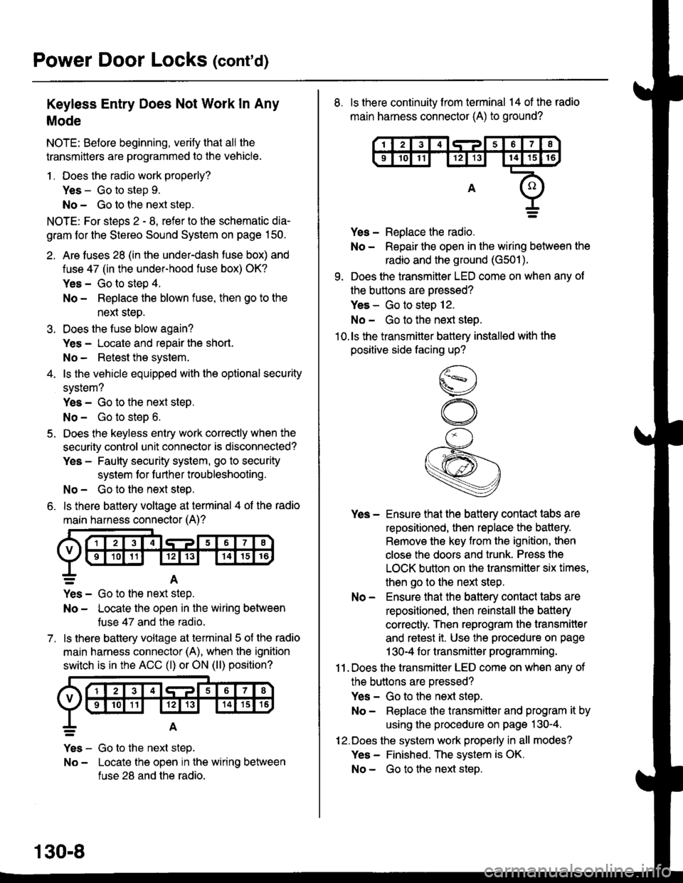
6. ls there battery voltage at terminal 4 of the radio
main harness connector (A)?
7.
=A
Yes - Go to the nen step.
No - Locate the open in the wiring between
tuse 47 and the radio.
ls there battery voltage at terminal 5 of the radio
main harness connector (A), when the ignition
switch is in the ACC (l) or ON (ll) position?
Yes - Go to the next step.
No - Locate the open in the wiring between
fuse 28 and the radio.
130-8
8. ls there continuity from terminal 14 of the radio
main harness connector (A) to ground?
Yes - Replace the radio.
No - Repair the open in the wiring between the
radio and the ground (G501).
9. Does the transmitter LED come on when any ot
the buttons are oressed?
Yes - Go to steo 12.
No - Go to the next steo.'10.ls the transmitter battery installed with the
positive side facing up?
Yes - Ensure that the battery contact tabs are
repositioned, then replace the battery.
Remove the key from the ignition, then
close the doors and trunk. Press the
LOCK button on the transmitter six times,
then go to the next step.
No - Ensure that the baftery contact tabs are
repositioned, then reinstall the batlery
correctly. Then reprogram the transmitter
and retest it. Use the procedure on page
1 30-4 f or transmitter programming.
11 . Does the transmitter LED come on when any of
the buttons are oressed?
Yes - Go to the next step.
No - Replace the transmitter and program it by
using the procedure on page 130-4.
12.Does the system work properly in all modes?
Yes - Finished. The system is OK.
No - Go to the next steD.
Page 2109 of 2189
Connector Views (cont'd)
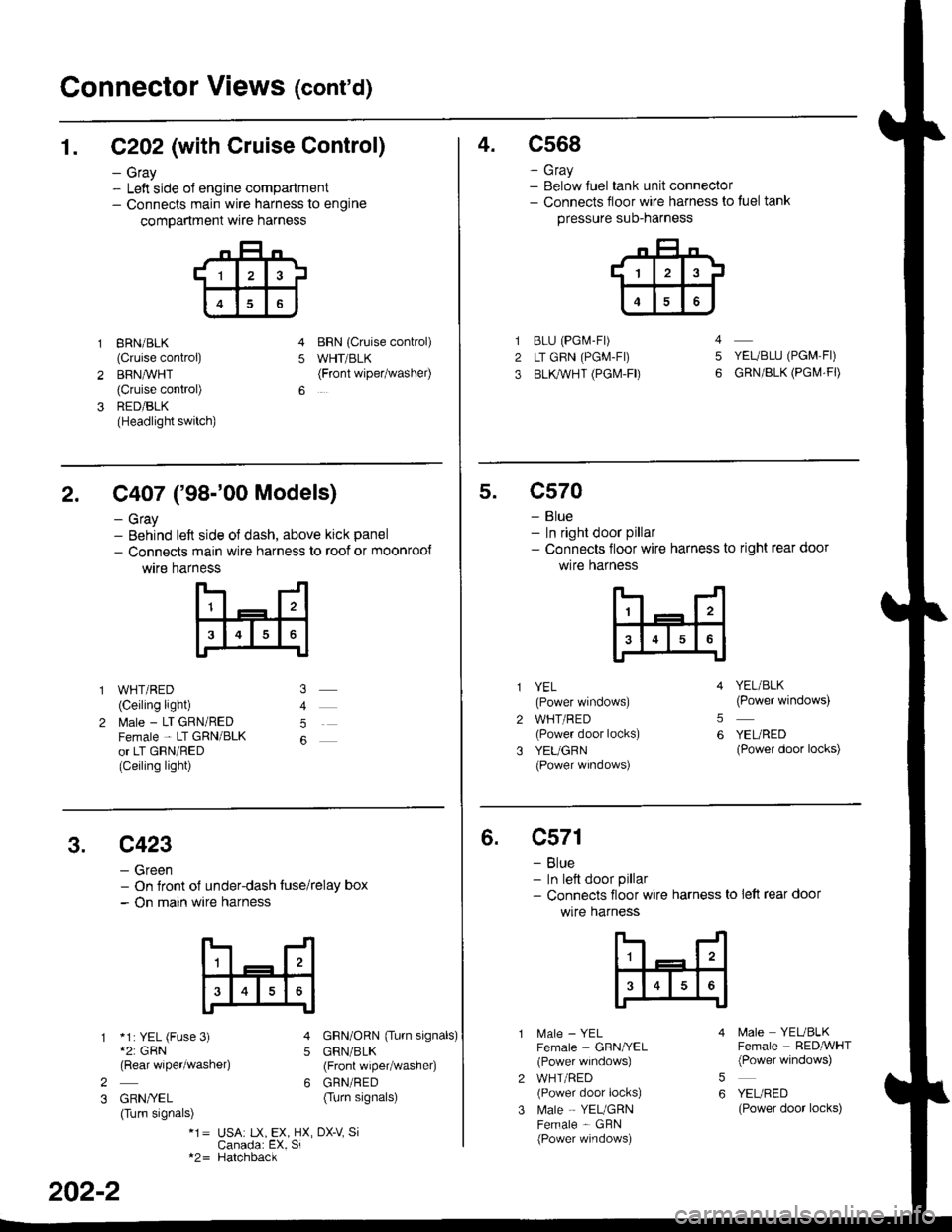
1. C202 (with Cruise Control)
- Gray- Left side ol engine compartment- Connects main wire harness to engine
compartment wre harness
gRN/BLK
(Cruise control)
BRN,ryVHT(Cruise control)
RED/BLK(Headlight switch)
BRN {Cruise conkol)
WHT/BLK(Front wipetwashel)5
4.c568
- Gray- Below Juel tank unit connector- Connects floor wire harness to tuel tank
pressure suo-narness
BLU (PGi.4-Fr)
LT GRN (PGM-FI)
BLl(WHT (PGI\4-FD
YEUBLU (PGM,FI)
GRN/BLK (PGI\,4.FD
4
5
2. C407 ('98-'00 Models)
- Gray- Behind left side ol dash, above kick panel
- Connects main wire harness to roof or moonroo{
wtre harness
WHT/RED(Ceiling light)
l\4ale - LT GRN/REDFemale - LT GRN/BLKor LT GRN/RED(Ceiling light)
5
5.c570
- Blue- In right door pillar- Connects floor wire harness to right rear door
wlre hafness
2
3
YEL(Power windows)
WHT/RED(Power door locks)
YEUGRN(Power wrndows)
YEL/BLK(Power windows)
YEURED(Power door locks)
5
6
3.c423
- Green- On Jront of under-dash tuse/relay box- On main wire harness
*1: YEL (Fuse 3)*2: GRN(Rear wiper/washe4
GRN/YEL(Turn signals)
GRN/ORN {Tu.n signals)
GRN/BLK(Front wiper/washer)
GRN/RED(Turn signals)
5
62
3
*1= USA: tX, EX, HX, DX-V SiCanada: EX, Si*2= Hatchback
202-2
6.c571
- Blue- In lett door pillar- Connects floor wire harness to lett rear door
wlre harness
MaIe _ YELFemale - GBN/YEL(Power windows)
WHT/RED(Power door locks)
Male - YEUGRNFemale - GBN(Power windows)
5
6
N4ale YEUBLKFemale - RED,ryVHT(Power windows)
YEURED(Power door locks)
Page 2110 of 2189
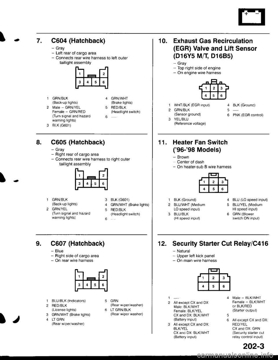
\7. C604 (Hatchback)
GRN/BLK(Back-up lights)
l\4ale GRNIYELFemale - GRN/RED(Turn signaland hazardwarning lights)
BLK (G601)
- Gray- Left rear ol cargo area- Connects rear wire harness to left outer
taillight assembly
4
5
6
1
2
GRNAVHT(Brake lights)
FED/BLK(Headllght switch)
10. Exhaust Gas Recirculation
(EGR) Valve and Lift Sensor
1
2
3
(D16Y5 MfI D1685)
- Gray- Top right side of engine- On engine wire harness
WHT/BLK (EGR input)
GRN/BLK(Sensor ground)
YEUBLU(Reference voltage)
4
5
6
BLK (Ground)
PNK (EGR control)
of cargo area
rear wire harness to right outer
assembly
n- -n
a t | _ a2a
l3I4t5tttl
IJ
I
8. C605 (Hatchback)
- Gray- Right rear- Connects
taillight
GRN/BLK(Back-up lights)
GRNTYEL(Turn signaland hazardwarning lights)
3
4
5
6
1
2
BLK (G601)
GFNAVHT (Brake lights)
RED/BLK(Headlight switch)
11. Heater Fan Switch
('96-'98 Models)
- Brown
Center of dash- On heater-sub B wire harness
BLK (Ground)
BLUAVHT (L4edium
LO speed input)
BLU/BLK(Hl speed input)
4
5
6
1
2
3
BLU (LO speed input)
BLU/YEL (Medium
Hlspeed input)
GFIN (Blowerswitch ON input)
9. C607 (Hatchback)
- Blue- Right side o{ cargo area- On rear wire harness
BLU/BLK (lndicators)
RED/BLK(License lights)
GBN,ryVHT (8rake lights)
LT GBN(Rear wiper/washe0
5
6
1
2
3
4
GRN(Rear wiper/washer)
LT GRN/BLK(Rear \/iper washer)
)/
202-3
12. Security Starter Cut Relay/C416
- Natural* Upper left kick panel- On main wire harness
1
2Allexcept CX and DXI[,4ale: BLK,^r'r'HTFemale: BLKI/ELCX and DXi BLI(WHT(Battery input)
All except CX and DX:BLK^/ELCX and DX: BLK/WHT(Baftery input)
[.4ale - BLK/WHTFemale - BLKAVHTor BLKRED(Starter output)
All excepi CX and DX:RED/YELCX and DX: GRN(Security starter c!1relay control inpul)
5
6
tl3'