1996 CHRYSLER VOYAGER Vtss
[x] Cancel search: VtssPage 515 of 1938

VEHICLE THEFT SECURITY SYSTEM
CONTENTS
page page
GENERAL INFORMATION
INTRODUCTION......................... 1
DESCRIPTION AND OPERATION
ARMING PROCEDURE.................... 1
TIME-OUT PERIOD....................... 2
TRIGGERING THE VTSS................... 2
DIAGNOSIS AND TESTING
DIAGNOSTIC PROCEDURES................ 2
REMOVAL AND INSTALLATION
BODY CONTROL MODULE................. 2DOOR LOCK CYLINDER SWITCH............ 2
FRONT DOOR AJAR (VTSS TRIGGER)
SWITCH.............................. 2
HOOD AJAR (VTSS TRIGGER) SWITCH...... 3
LIFTGATE AJAR (VTSS TRIGGER) SWITCH.... 3
LIFTGATE LOCK CYLINDER SWITCH......... 3
SLIDING DOOR AJAR (VTSS TRIGGER)
SWITCH.............................. 4
GENERAL INFORMATION
INTRODUCTION
Vehicles equipped with the Vehicle Theft Security
System (VTSS) system, the doors, liftgate, hood and
ignition circuit are monitored by the Body Control
Module (BCM) when the system is armed. The VTSS
will prevent the engine from starting until the BCM
receives a disarm signal. If the VTSS is triggered,
the horn will pulse, headlamps/marker lamps will
flash, and the VTSS warning lamp will flash. If BCM
determines the threat to be false and the VTSS is not
triggered again, the system will shut down and
rearm itself after three minutes. The VTSS monitor-
ing portion of the system is split into two sections.
The engine compartment section and the passenger
compartment section. If a malfunction occurs in the
engine compartment section, the passenger compart-
ment section would still arm and function normally.
If an electrical malfunction occurs in either section of
the system a Diagnostic Trouble Code (DTC) would
be stored the BCM memory to aid system repair.
DTCs can be retrieved using scan tool (DRB)
attached to the diagnostic connector above the accel-
erator pedal.
ENABLING
To initialize the VTSS feature the operator must,
with the engine compartment hood open, cycle the
key in the liftgate key cylinder to the unlock position
giving the BCM a disarm signal. At this time the
visual alarm outputs the headlamps and marker
lamps will function. However the audio alarm output
the horn and engine disable portion of the VTSS will
not function until there has been twenty consecutiveengine run cycles. When this has occurred the total
VTSS will function.
If during alarm being set the BCM receives a
request from the RKE module to enter PANIC mode
the BCM will cancel the alarm, return VTSS armed
state and then perform the RKE PANIC feature.
DESCRIPTION AND OPERATION
ARMING PROCEDURE
METHOD-A
(1) With the key removed from the ignition lock
and any door open, actuate one of the following:
²Power door lock button to LOCK,
²Key fob LOCK button
²Door lock key cylinder to locked position.
(2) Close all opened doors.
(3) After the last door is closed, an arming time-
out period of sixteen seconds will start, then the
VTSS will become armed.
METHOD-B
Actuating the key fob transmitter LOCK button,
key locking the front doors or liftgate with the doors
closed and the ignition locked will begin the arming
time-out period. If method-A, 16 second time-out
sequence was in process when method-B was actu-
ated, the 16 second time-out will restart from the
time of the second actuation.
If the security lamp does not illuminate at all upon
final door closure, it indicates that the system is not
arming.
The current VTSS status armed or disarmed shall
be maintained in memory to prevent battery discon-
nects from disarming the system.
NSVEHICLE THEFT SECURITY SYSTEM 8Q - 1
Page 516 of 1938

TIME-OUT PERIOD
The VTSS requires 16 consecutive seconds to time-
out and arm the alarm. If a door is key unlocked, key
fob unlocked. or the ignition is switched ON, the
VTSS will cancel out. To reset the VTSS, perform
methods A or B.
TRIGGERING THE VTSS
After the VTSS is armed, following actions will
trigger the alarm:
²Opening any door.
²Opening the hood
²Turning the ignition to the ON or unlock posi-
tion.
²The ignition switch can be turned to the acces-
sory position without triggering alarm system.
DIAGNOSIS AND TESTING
DIAGNOSTIC PROCEDURES
Refer to Group 8W, Wiring Diagrams for circuit
information and component locations. Using a scan
tool (DRB). Refer to the proper Body Diagnostic Pro-
cedures manual for test procedures.
REMOVAL AND INSTALLATION
BODY CONTROL MODULE
REMOVAL
(1) Disconnect the battery negative cable.
(2) Remove the lower steering column cover and
the knee blocker reinforcement.
(3) Disconnect the two wire connectors from the
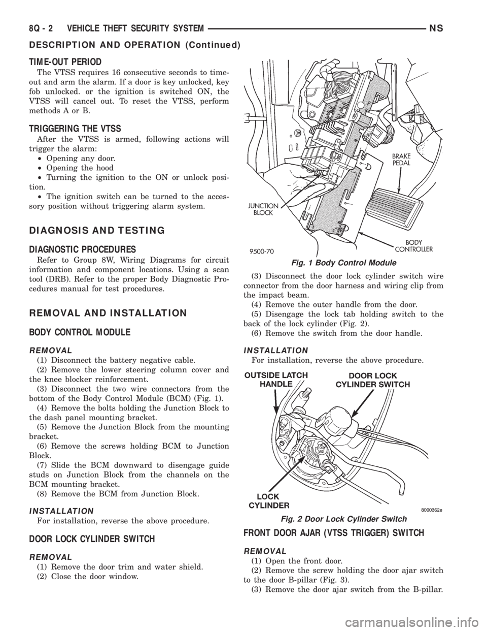
bottom of the Body Control Module (BCM) (Fig. 1).
(4) Remove the bolts holding the Junction Block to
the dash panel mounting bracket.
(5) Remove the Junction Block from the mounting
bracket.
(6) Remove the screws holding BCM to Junction
Block.
(7) Slide the BCM downward to disengage guide
studs on Junction Block from the channels on the
BCM mounting bracket.
(8) Remove the BCM from Junction Block.
INSTALLATION
For installation, reverse the above procedure.
DOOR LOCK CYLINDER SWITCH
REMOVAL
(1) Remove the door trim and water shield.
(2) Close the door window.(3) Disconnect the door lock cylinder switch wire
connector from the door harness and wiring clip from
the impact beam.
(4) Remove the outer handle from the door.
(5) Disengage the lock tab holding switch to the
back of the lock cylinder (Fig. 2).
(6) Remove the switch from the door handle.
INSTALLATION
For installation, reverse the above procedure.
FRONT DOOR AJAR (VTSS TRIGGER) SWITCH
REMOVAL
(1) Open the front door.
(2) Remove the screw holding the door ajar switch
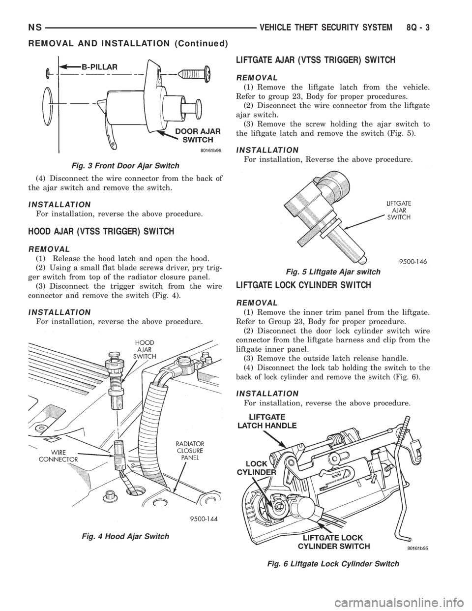
to the door B-pillar (Fig. 3).
(3) Remove the door ajar switch from the B-pillar.
Fig. 1 Body Control Module
Fig. 2 Door Lock Cylinder Switch
8Q - 2 VEHICLE THEFT SECURITY SYSTEMNS
DESCRIPTION AND OPERATION (Continued)
Page 517 of 1938

(4) Disconnect the wire connector from the back of
the ajar switch and remove the switch.
INSTALLATION
For installation, reverse the above procedure.
HOOD AJAR (VTSS TRIGGER) SWITCH
REMOVAL
(1) Release the hood latch and open the hood.
(2) Using a small flat blade screws driver, pry trig-
ger switch from top of the radiator closure panel.
(3) Disconnect the trigger switch from the wire
connector and remove the switch (Fig. 4).
INSTALLATION
For installation, reverse the above procedure.
LIFTGATE AJAR (VTSS TRIGGER) SWITCH
REMOVAL
(1) Remove the liftgate latch from the vehicle.
Refer to group 23, Body for proper procedures.
(2) Disconnect the wire connector from the liftgate
ajar switch.
(3) Remove the screw holding the ajar switch to
the liftgate latch and remove the switch (Fig. 5).
INSTALLATION
For installation, Reverse the above procedure.
LIFTGATE LOCK CYLINDER SWITCH
REMOVAL
(1) Remove the inner trim panel from the liftgate.
Refer to Group 23, Body for proper procedure.
(2) Disconnect the door lock cylinder switch wire
connector from the liftgate harness and clip from the
liftgate inner panel.
(3) Remove the outside latch release handle.
(4)
Disconnect the lock tab holding the switch to the
back of lock cylinder and remove the switch (Fig. 6).
INSTALLATION
For installation, reverse the above procedure.
Fig. 3 Front Door Ajar Switch
Fig. 4 Hood Ajar Switch
Fig. 5 Liftgate Ajar switch
Fig. 6 Liftgate Lock Cylinder Switch
NSVEHICLE THEFT SECURITY SYSTEM 8Q - 3
REMOVAL AND INSTALLATION (Continued)
Page 518 of 1938

SLIDING DOOR AJAR (VTSS TRIGGER) SWITCH
REMOVAL
(1) Release the sliding door latch and allow back of
the door to pop open.
(2) Through opening at the rear edge of the sliding
door on outside of the vehicle, pry door ajar switch
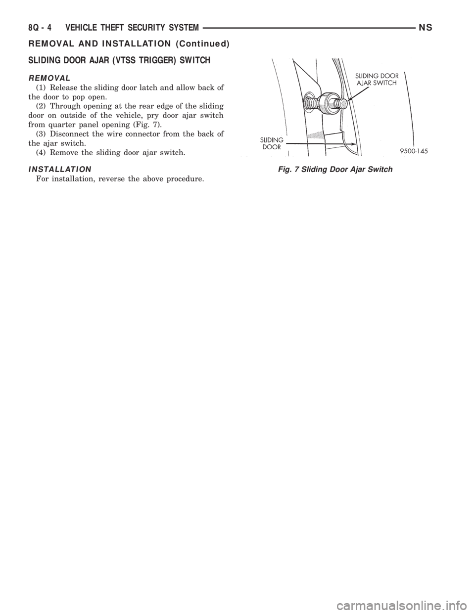
from quarter panel opening (Fig. 7).
(3) Disconnect the wire connector from the back of
the ajar switch.
(4) Remove the sliding door ajar switch.
INSTALLATION
For installation, reverse the above procedure.
Fig. 7 Sliding Door Ajar Switch
8Q - 4 VEHICLE THEFT SECURITY SYSTEMNS
REMOVAL AND INSTALLATION (Continued)
Page 579 of 1938

Component Page
Seat Belt Indicator Lamp.................8W-40
Seat Belt Switch........................8W-40
Sentry Key Immobilizer Module............8W-39
Service Engine Soon Lamp.............8W-30, 46
Sliding Door Contacts....................8W-61
Sliding Door Lock Motors.................8W-61
Speed Control Switches...............8W-30, 33
Speedometer...........................8W-40
Stop Lamp Switch...................8W-33, 51
Stop/Turn Signal Relays..................8W-54
Tachometer............................8W-40
Tail/Stop Lamp.........................8W-51
Tail/Turn Signal Lamp................8W-51, 52
Throttle Position Sensor..................8W-30
Traction Control Switch..................8W-35
Trailer Tow Connector...................8W-54
Transmission Control Module..............8W-31
Transmission Control Relay............8W-10, 31
Transmission Control Solenoids............8W-31
Transmission Range Sensor...............8W-31
Trip Odometer.........................8W-40Component Page
Turbine Speed Sensor....................8W-31
Turbo Boost Pressure Sensor..............8W-30
Turn Indicators......................8W-46, 52
Turn Signal/Hazard Switch............8W-46, 52
Underdrive Solenoid.....................8W-31
Universal Garage Door Opener............8W-49
Vacuum Solenoid.......................8W-33
Vehicle Speed Control Servo...............8W-33
Vehicle Speed Sensor....................8W-30
Vent Motors...........................8W-60
Vent Solenoids.........................8W-33
Visor/Vanity Mirror Lamps................8W-44
Voltage Regulator.......................8W-20
Volts Indicator Lamp....................8W-40
VTSS Lamp........................8W-39, 46
Washer Module.........................8W-53
Wheel Speed Sensors....................8W-35
Wiper High/Low Relay...................8W-53
Wiper Module..........................8W-53
Wiper On Relay........................8W-53
NS/GS8W - 02 COMPONENT INDEX 8W - 02 - 3
Page 723 of 1938

8W-39 VEHICLE THEFT SECURITY SYSTEM
Component Page
Body Control Module...............8W-39-2, 3, 4
BS19...............................8W-39-2
Clockspring..........................8W-39-2
Driver Door Ajar Switch................8W-39-2
Driver Door Arm/Disarm Switch..........8W-39-3
Driver Door Lock Switch................8W-39-3
Fuse 9 (PDC).........................8W-39-2
Fuse 18 (PDC)........................8W-39-5
Fuse 28 (PDC)........................8W-39-2
G200...............................8W-39-5
G301...........................8W-39-2, 3, 4
G302...............................8W-39-4
G400.............................8W-39-3, 4
High Note Horn.......................8W-39-2
Hood Ajar Switch.....................8W-39-4
Horn Relay..........................8W-39-2
Horn Switch.........................8W-39-2
Junction Block......................8W-39-2, 5Component Page
Left Rear Door Ajar Switch..............8W-39-4
Liftgate Ajar Switch...................8W-39-4
Liftgate Arm/Disarm Switch.............8W-39-3
Low Note Horn.......................8W-39-2
Memory Seat/Mirror Module.............8W-39-2
Message Center.......................8W-39-2
Passenger Door Ajar Switch.............8W-39-2
Passenger Door Arm/Disarm Switch.......8W-39-3
Passenger Door Lock Switch.............8W-39-3
Power Distribution Center.............8W-39-2, 5
PS01...............................8W-39-5
PS02...............................8W-39-5
PTC 1 (JB)..........................8W-39-5
Remote Keyless Entry Module...........8W-39-2
Right Rear Door Ajar Switch.............8W-39-4
Sentry Key Immobilizer Module..........8W-39-5
VTSS Lamp..........................8W-39-2
NS/GS8W - 39 VEHICLE THEFT SECURITY SYSTEM 8W - 39 - 1
Page 724 of 1938

8587
3086
RELAY HORN
C248C2
20A
FUSE
9
BATT A0
POWER
DISTRIBUTION
CENTER
13 12
VTSS
LAMP
CENTER MESSAGE
28FUSE10A
C35
JUNCTION
BLOCK
6C4
13C1
C2
169
BODY
CONTROL
MODULE
VTSS
LAMP
DRIVERFUSED
B (+) RELAYHORN
18
CONTROL
M1
20
PKG69
22
BK/OR
M1
20
PK
C116
MODULE MIRROR
SEAT/
MEMORY
M1
20
PK
C24
GY/OR20 X4
79C1 C148
SENSE SWITCHAJAR DRIVER
DOOR DOOR PASSENGER
AJAR
SWITCH
SENSE
DRIVER
DOOR
AJAR
SWITCH
SWITCH AJAR
DOOR PASSENGER
G75
18
TNG74
18
TN/RD
HORN NOTE
LOW HIGH
NOTE
HORN
X2
18
DG/RD
X2
18
DG/RDX2
18
DG/RD
BS19
A A
BB
Z1
18
BK
Z1
18
BK
G301
FUSED
B (+)
1 13
HORN
SWITCH CLOCKSPRING
X3
20
BK/RD
20C2
1X3
20
BK/RD
CONTROLRELAYHORN
*7 *8
* RHD
C2
3
MODULE ENTRY
KEYLESS
REMOTE
7P50
NOT
USED
M1
20
PK
M1
22
PK
(8W-10-30) (8W-10-8)
(8W-10-9)
(8W-10-10)
(8W-46-2) (8W-10-11)
(8W-12-2)
(8W-45-3)
(8W-45-7)(8W-62-3)
(8W-63-4)
(8W-15-10)
(8W-15-11)(8W-41-2) (8W-41-2)(8W-61-5) (8W-12-20)
8W - 39 - 2 8W-39 VEHICLE THEFT SECURITY SYSTEMNS/GS
J988W-3GS003902
Page 773 of 1938

BODY
CONTROL
MODULE
BLOCK JUNCTION
15
RELAYBEAMLOW
CONTROL
33C3
L93
22
PK
4
19
SIGNALLEFT
REAR
TURN TURNREAR RIGHT
SIGNAL 21
5COMBINATION
FLASHER/
DRL
MODULE LEFT
REAR
TURN
SIGNAL SIGNALTURN REAR RIGHT 912 CONTROLRELAYBEAM HIGH/LOW
4C2
C2
1
G26
20
LB
SWITCH IGNITION
13
BK/OR22 G69
16C2CENTER MESSAGE
KEY-IN
SWITCH
SENSE FEEDLAMPSPANEL
2
C4830
INSTRUMENT
CLUSTER
6
11
C1C4
8
SWITCH CONTROL
FRONT
BLOWER
REAR
IGNITIONDRIVERLAMP INDICATORVTSS
OR20 E2 E2
20
OR
OR20 E2
23C4
OR20 E2
ASH
RECEIVER
LAMP
2
E2
18
OR
C21
SWITCH HEADLAMP
E2
20
OR
C41
OR20 E2
C15
RADIO
5
POWER
MIRROR
SWITCH
3
TRACTION
CONTROL
SWITCH
A/C
HEATER
CONTROL
85
(IN PDC) RELAY
BEAM
LOW
76C1
L193
20
OR/WT
CONTROLLOW
BEAM
RELAY
SWITCH) FUNCTION
MULTI-
(PART OF
SWITCH
DIMMER
HEADLAMP
E2
20
OR
*7
*1
* RHD
86
FRONT
CIGAR
LIGHTER/
POWER
OUTLET
TOE2
20
OR
FEED LAMPSPANEL
FEED LAMPSPANEL
FEED LAMPSPANELFEED LAMPSPANELFEED LAMPSPANEL
FEED LAMPSPANEL
FEED LAMPSPANEL PANEL
LAMPS
FEED
KEY-IN
IGNITION
SWITCH
SENSEVTSS
INDICATOR
LAMP
DRIVERHIGH/LOW
BEAM
RELAY
CONTROL
(8W-12-2)
(8W-50-2)
(8W-50-12)
(8W-51-3)
(8W-10-14)(8W-46-2)
(8W-40-4)
(8W-42-6)(8W-44-7)
(8W-50-9)
(8W-50-10)(8W-47-2)(8W-62-2)
(8W-62-4) (8W-35-2)
(8W-42-3) (8W-50-2)(8W-50-2)
(8W-41-3)
NS/GS8W-45 BODY CONTROL MODULE 8W - 45 - 5
GS004505J988W-3