Page 1113 of 1938
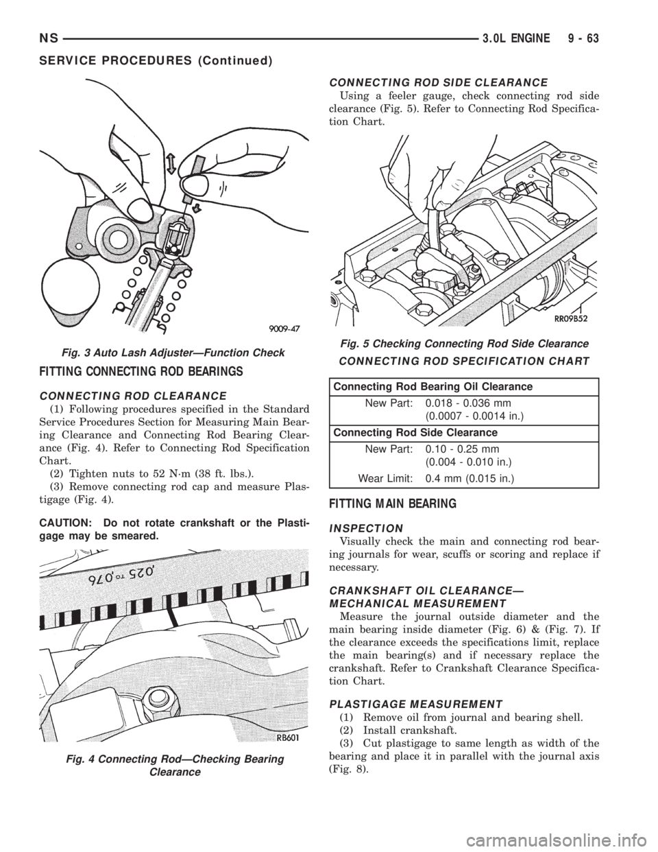
FITTING CONNECTING ROD BEARINGS
CONNECTING ROD CLEARANCE
(1) Following procedures specified in the Standard
Service Procedures Section for Measuring Main Bear-
ing Clearance and Connecting Rod Bearing Clear-
ance (Fig. 4). Refer to Connecting Rod Specification
Chart.
(2) Tighten nuts to 52 N´m (38 ft. lbs.).
(3) Remove connecting rod cap and measure Plas-
tigage (Fig. 4).
CAUTION: Do not rotate crankshaft or the Plasti-
gage may be smeared.
CONNECTING ROD SIDE CLEARANCE
Using a feeler gauge, check connecting rod side
clearance (Fig. 5). Refer to Connecting Rod Specifica-
tion Chart.
FITTING MAIN BEARING
INSPECTION
Visually check the main and connecting rod bear-
ing journals for wear, scuffs or scoring and replace if
necessary.
CRANKSHAFT OIL CLEARANCEÐ
MECHANICAL MEASUREMENT
Measure the journal outside diameter and the
main bearing inside diameter (Fig. 6) & (Fig. 7). If
the clearance exceeds the specifications limit, replace
the main bearing(s) and if necessary replace the
crankshaft. Refer to Crankshaft Clearance Specifica-
tion Chart.
PLASTIGAGE MEASUREMENT
(1) Remove oil from journal and bearing shell.
(2) Install crankshaft.
(3) Cut plastigage to same length as width of the
bearing and place it in parallel with the journal axis
(Fig. 8).
Fig. 3 Auto Lash AdjusterÐFunction Check
Fig. 4 Connecting RodÐChecking Bearing
Clearance
Fig. 5 Checking Connecting Rod Side Clearance
CONNECTING ROD SPECIFICATION CHART
Connecting Rod Bearing Oil Clearance
New Part: 0.018 - 0.036 mm
(0.0007 - 0.0014 in.)
Connecting Rod Side Clearance
New Part: 0.10 - 0.25 mm
(0.004 - 0.010 in.)
Wear Limit: 0.4 mm (0.015 in.)
NS3.0L ENGINE 9 - 63
SERVICE PROCEDURES (Continued)
Page 1115 of 1938
CHECKING CRANKSHAFT END PLAY
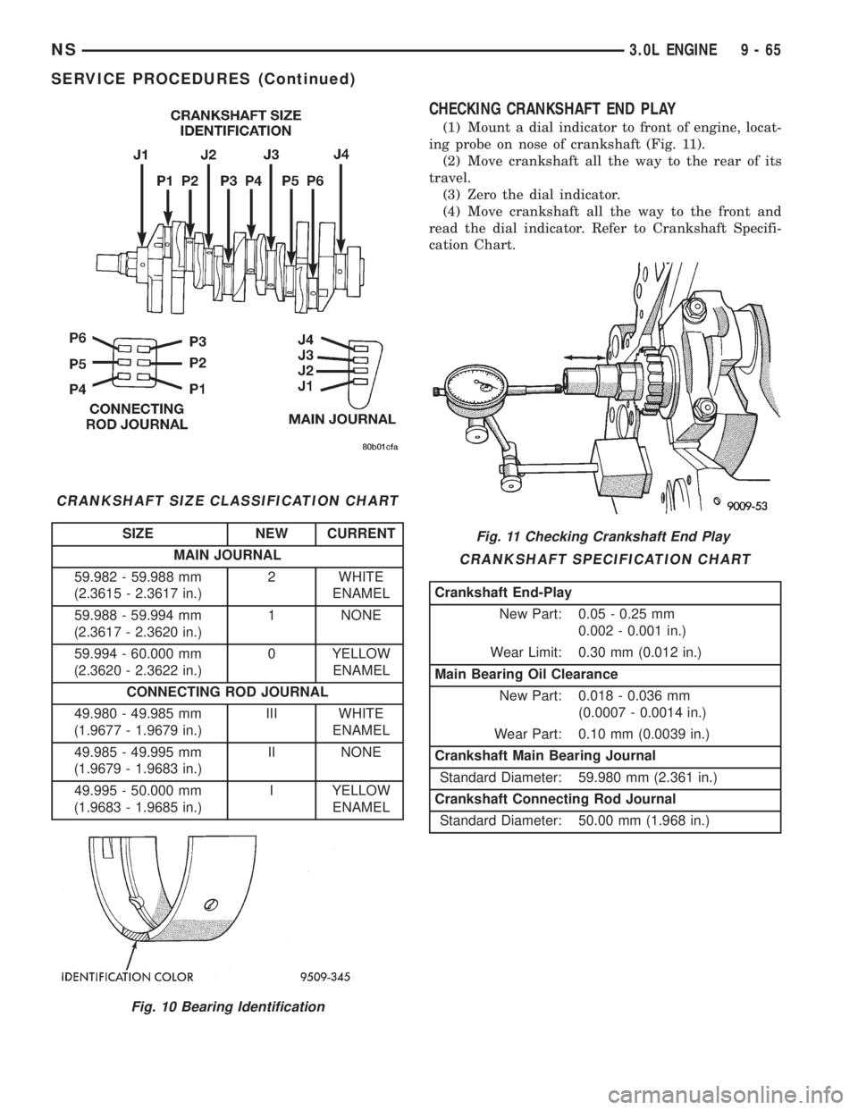
(1) Mount a dial indicator to front of engine, locat-
ing probe on nose of crankshaft (Fig. 11).
(2) Move crankshaft all the way to the rear of its
travel.
(3) Zero the dial indicator.
(4) Move crankshaft all the way to the front and
read the dial indicator. Refer to Crankshaft Specifi-
cation Chart.
CRANKSHAFT SIZE CLASSIFICATION CHART
SIZE NEW CURRENT
MAIN JOURNAL
59.982 - 59.988 mm
(2.3615 - 2.3617 in.)2 WHITE
ENAMEL
59.988 - 59.994 mm
(2.3617 - 2.3620 in.)1 NONE
59.994 - 60.000 mm
(2.3620 - 2.3622 in.)0 YELLOW
ENAMEL
CONNECTING ROD JOURNAL
49.980 - 49.985 mm
(1.9677 - 1.9679 in.)III WHITE
ENAMEL
49.985 - 49.995 mm
(1.9679 - 1.9683 in.)II NONE
49.995 - 50.000 mm
(1.9683 - 1.9685 in.)I YELLOW
ENAMEL
Fig. 10 Bearing Identification
Fig. 11 Checking Crankshaft End Play
CRANKSHAFT SPECIFICATION CHART
Crankshaft End-Play
New Part: 0.05 - 0.25 mm
0.002 - 0.001 in.)
Wear Limit: 0.30 mm (0.012 in.)
Main Bearing Oil Clearance
New Part: 0.018 - 0.036 mm
(0.0007 - 0.0014 in.)
Wear Part: 0.10 mm (0.0039 in.)
Crankshaft Main Bearing Journal
Standard Diameter: 59.980 mm (2.361 in.)
Crankshaft Connecting Rod Journal
Standard Diameter: 50.00 mm (1.968 in.)
NS3.0L ENGINE 9 - 65
SERVICE PROCEDURES (Continued)
Page 1121 of 1938
(6) When removing right cylinder head cover, dis-
connect generator wiring and remove generator.
(7) Relocate spark plug wires.
(8) Remove vacuum connections.
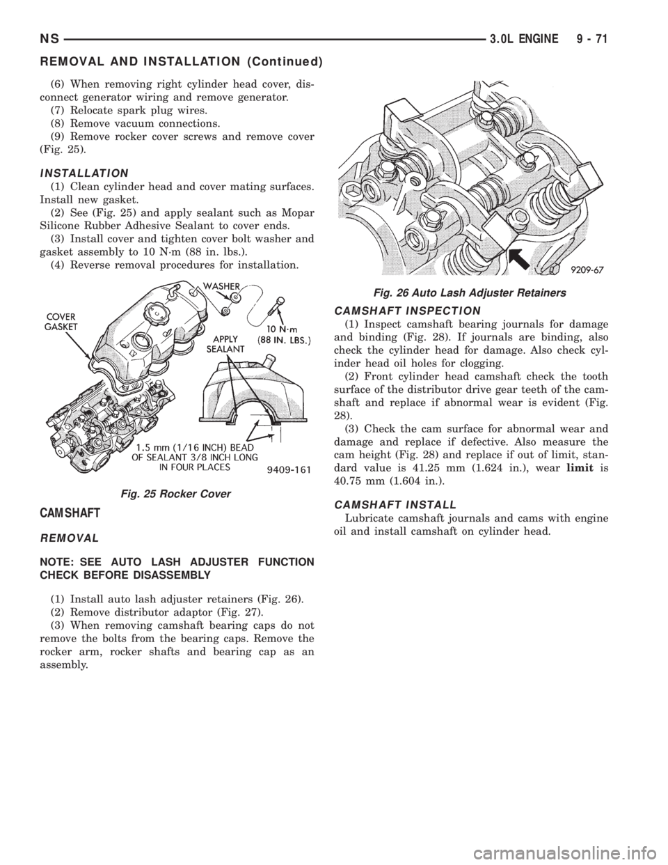
(9) Remove rocker cover screws and remove cover
(Fig. 25).
INSTALLATION
(1) Clean cylinder head and cover mating surfaces.
Install new gasket.
(2) See (Fig. 25) and apply sealant such as Mopar
Silicone Rubber Adhesive Sealant to cover ends.
(3) Install cover and tighten cover bolt washer and
gasket assembly to 10 N´m (88 in. lbs.).
(4) Reverse removal procedures for installation.
CAMSHAFT
REMOVAL
NOTE: SEE AUTO LASH ADJUSTER FUNCTION
CHECK BEFORE DISASSEMBLY
(1) Install auto lash adjuster retainers (Fig. 26).
(2) Remove distributor adaptor (Fig. 27).
(3) When removing camshaft bearing caps do not
remove the bolts from the bearing caps. Remove the
rocker arm, rocker shafts and bearing cap as an
assembly.
CAMSHAFT INSPECTION
(1) Inspect camshaft bearing journals for damage
and binding (Fig. 28). If journals are binding, also
check the cylinder head for damage. Also check cyl-
inder head oil holes for clogging.
(2) Front cylinder head camshaft check the tooth
surface of the distributor drive gear teeth of the cam-
shaft and replace if abnormal wear is evident (Fig.
28).
(3) Check the cam surface for abnormal wear and
damage and replace if defective. Also measure the
cam height (Fig. 28) and replace if out of limit, stan-
dard value is 41.25 mm (1.624 in.), wearlimitis
40.75 mm (1.604 in.).
CAMSHAFT INSTALL
Lubricate camshaft journals and cams with engine
oil and install camshaft on cylinder head.
Fig. 25 Rocker Cover
Fig. 26 Auto Lash Adjuster Retainers
NS3.0L ENGINE 9 - 71
REMOVAL AND INSTALLATION (Continued)
Page 1129 of 1938
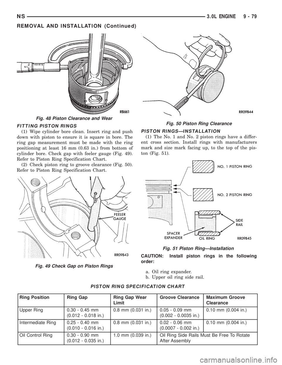
FITTING PISTON RINGS
(1) Wipe cylinder bore clean. Insert ring and push
down with piston to ensure it is square in bore. The
ring gap measurement must be made with the ring
positioning at least 16 mm (0.63 in.) from bottom of
cylinder bore. Check gap with feeler gauge (Fig. 49).
Refer to Piston Ring Specification Chart.
(2) Check piston ring to groove clearance (Fig. 50).
Refer to Piston Ring Specification Chart.PISTON RINGSÐINSTALLATION
(1) The No. 1 and No. 2 piston rings have a differ-
ent cross section. Install rings with manufacturers
mark and size mark facing up, to the top of the pis-
ton (Fig. 51).
CAUTION: Install piston rings in the following
order:
a. Oil ring expander.
b. Upper oil ring side rail.
PISTON RING SPECIFICATION CHART
Ring Position Ring Gap Ring Gap Wear
LimitGroove Clearance Maximum Groove
Clearance
Upper Ring 0.30 - 0.45 mm
(0.012 - 0.018 in.)0.8 mm (0.031 in.) 0.05 - 0.09 mm
(0.002 - 0.0035 in.)0.10 mm (0.004 in.)
Intermediate Ring 0.25 - 0.40 mm
(0.010 - 0.016 in.)0.8 mm (0.031 in.) 0.02 - 0.06 mm
(0.0007 - 0.002 in.)0.10 mm (0.004 in.)
Oil Control Ring 0.30 - 0.90 mm
(0.012 - 0.035 in.)1.0 mm (0.039 in.) Oil Ring Side Rails Must Be Free To Rotate
After Assembly
Fig. 48 Piston Clearance and Wear
Fig. 49 Check Gap on Piston Rings
Fig. 50 Piston Ring Clearance
Fig. 51 Piston RingÐInstallation
NS3.0L ENGINE 9 - 79
REMOVAL AND INSTALLATION (Continued)
Page 1130 of 1938
c. Lower oil ring side rail.
d. No. 2 Intermediate piston ring.
e. No. 1 Upper piston ring.
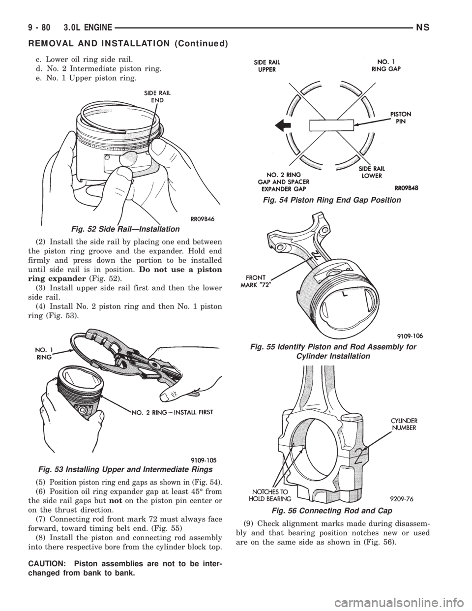
(2) Install the side rail by placing one end between
the piston ring groove and the expander. Hold end
firmly and press down the portion to be installed
until side rail is in position.Do not use a piston
ring expander(Fig. 52).
(3) Install upper side rail first and then the lower
side rail.
(4) Install No. 2 piston ring and then No. 1 piston
ring (Fig. 53).
(5)
Position piston ring end gaps as shown in (Fig. 54).
(6) Position oil ring expander gap at least 45É from
the side rail gaps butnoton the piston pin center or
on the thrust direction.
(7) Connecting rod front mark 72 must always face
forward, toward timing belt end. (Fig. 55)
(8) Install the piston and connecting rod assembly
into there respective bore from the cylinder block top.
CAUTION: Piston assemblies are not to be inter-
changed from bank to bank.(9) Check alignment marks made during disassem-
bly and that bearing position notches new or used
are on the same side as shown in (Fig. 56).
Fig. 52 Side RailÐInstallation
Fig. 53 Installing Upper and Intermediate Rings
Fig. 54 Piston Ring End Gap Position
Fig. 55 Identify Piston and Rod Assembly for
Cylinder Installation
Fig. 56 Connecting Rod and Cap
9 - 80 3.0L ENGINENS
REMOVAL AND INSTALLATION (Continued)
Page 1134 of 1938
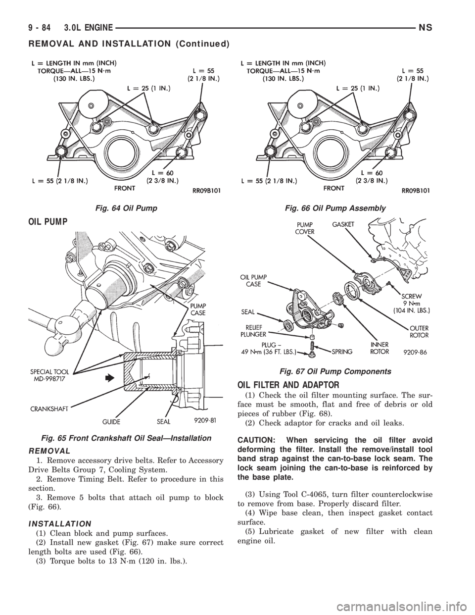
OIL PUMP
REMOVAL
1. Remove accessory drive belts. Refer to Accessory
Drive Belts Group 7, Cooling System.
2. Remove Timing Belt. Refer to procedure in this
section.
3. Remove 5 bolts that attach oil pump to block
(Fig. 66).
INSTALLATION
(1) Clean block and pump surfaces.
(2) Install new gasket (Fig. 67) make sure correct
length bolts are used (Fig. 66).
(3) Torque bolts to 13 N´m (120 in. lbs.).
OIL FILTER AND ADAPTOR
(1) Check the oil filter mounting surface. The sur-
face must be smooth, flat and free of debris or old
pieces of rubber (Fig. 68).
(2) Check adaptor for cracks and oil leaks.
CAUTION: When servicing the oil filter avoid
deforming the filter. Install the remove/install tool
band strap against the can-to-base lock seam. The
lock seam joining the can-to-base is reinforced by
the base plate.
(3) Using Tool C-4065, turn filter counterclockwise
to remove from base. Properly discard filter.
(4) Wipe base clean, then inspect gasket contact
surface.
(5) Lubricate gasket of new filter with clean
engine oil.
Fig. 64 Oil Pump
Fig. 65 Front Crankshaft Oil SealÐInstallation
Fig. 66 Oil Pump Assembly
Fig. 67 Oil Pump Components
9 - 84 3.0L ENGINENS
REMOVAL AND INSTALLATION (Continued)
Page 1135 of 1938
(6) Install new filter until gasket contacts base.
Tighten filter 1 turn or 20 N´m (15 ft. lbs.). Use filter
wrench if necessary.
(7) Start engine and check for leaks.
DISASSEMBLY AND ASSEMBLY
ROCKER ARMS AND SHAFTS
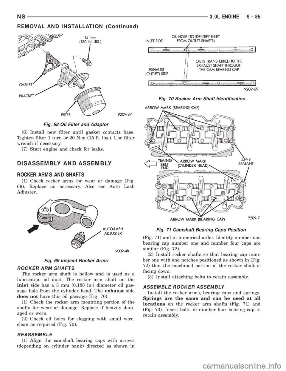
(1) Check rocker arms for wear or damage (Fig.
69). Replace as necessary. Also see Auto Lash
Adjuster.
ROCKER ARM SHAFTS
The rocker arm shaft is hollow and is used as a
lubrication oil duct. The rocker arm shaft on the
inletside hasa3mm(0.188 in.) diameter oil pas-
sage hole from the cylinder head. Theexhaustside
does nothave this oil passage (Fig. 70).
(1) Check the rocker arm mounting portion of the
shafts for wear or damage. Replace if heavily dam-
aged or worn.
(2) Check oil holes for clogging with small wire,
clean as required (Fig. 70).
REASSEMBLE
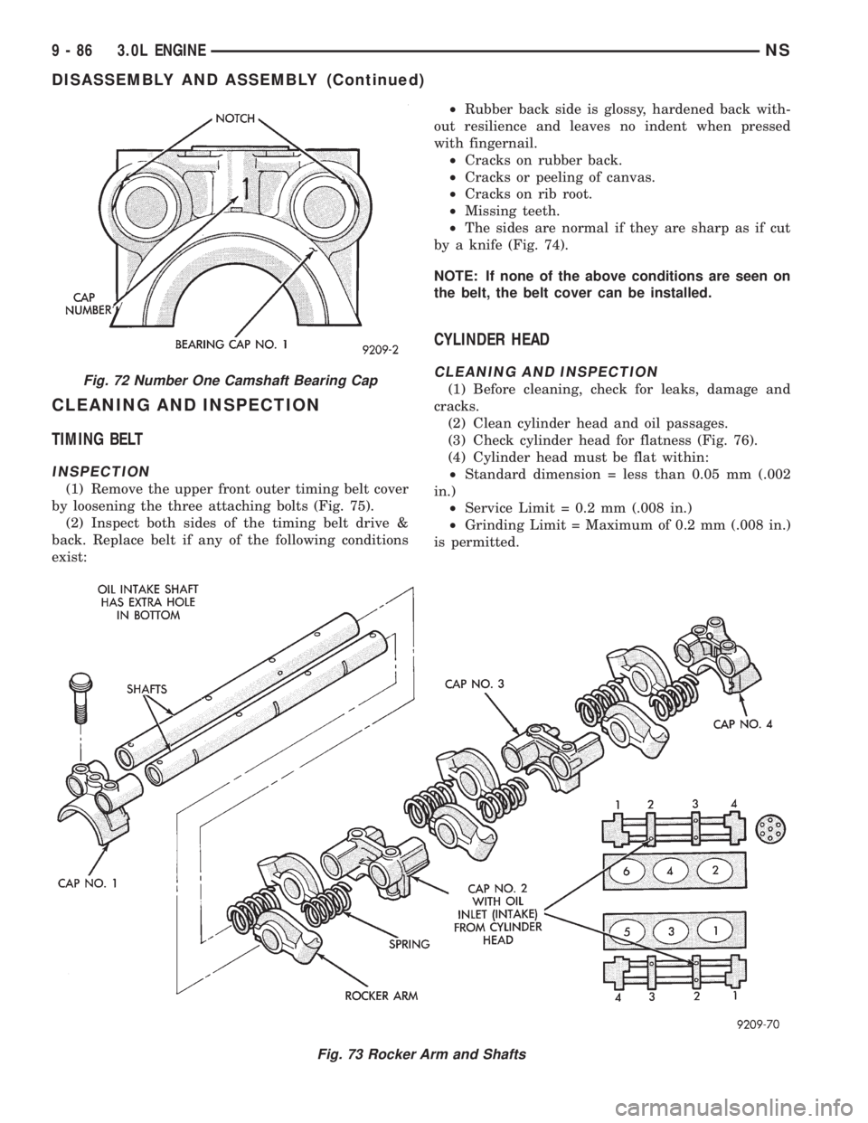
(1) Align the camshaft bearing caps with arrows
(depending on cylinder bank) directed as shown in(Fig. 71) and in numerical order. Identify number one
bearing cap number one and number four caps are
similar (Fig. 72).
(2) Install rocker shafts so that bearing cap num-
ber one with end notches positioned as shown in (Fig.
72) that the machined portion of the rocker shaft is
facing down.
(3) Install attaching bolts to retain assembly.
ASSEMBLE ROCKER ASSEMBLY
Install the rocker arms, bearing caps and springs.
Springs are the same and can be used at all
locationson the rocker arm shafts (Fig. 71) and
(Fig. 73). Insert bolts in number four bearing cap to
retain assembly.
Fig. 68 Oil Filter and Adaptor
Fig. 69 Inspect Rocker Arms
Fig. 70 Rocker Arm Shaft Identification
Fig. 71 Camshaft Bearing Caps Position
NS3.0L ENGINE 9 - 85
REMOVAL AND INSTALLATION (Continued)
Page 1136 of 1938
CLEANING AND INSPECTION
TIMING BELT
INSPECTION
(1) Remove the upper front outer timing belt cover
by loosening the three attaching bolts (Fig. 75).
(2) Inspect both sides of the timing belt drive &
back. Replace belt if any of the following conditions
exist:²Rubber back side is glossy, hardened back with-
out resilience and leaves no indent when pressed
with fingernail.
²Cracks on rubber back.
²Cracks or peeling of canvas.
²Cracks on rib root.
²Missing teeth.
²The sides are normal if they are sharp as if cut
by a knife (Fig. 74).
NOTE: If none of the above conditions are seen on
the belt, the belt cover can be installed.
CYLINDER HEAD
CLEANING AND INSPECTION
(1) Before cleaning, check for leaks, damage and
cracks.
(2) Clean cylinder head and oil passages.
(3) Check cylinder head for flatness (Fig. 76).
(4) Cylinder head must be flat within:
²Standard dimension = less than 0.05 mm (.002
in.)
²Service Limit = 0.2 mm (.008 in.)
²Grinding Limit = Maximum of 0.2 mm (.008 in.)
is permitted.
Fig. 73 Rocker Arm and Shafts
Fig. 72 Number One Camshaft Bearing Cap
9 - 86 3.0L ENGINENS
DISASSEMBLY AND ASSEMBLY (Continued)