1996 CHRYSLER VOYAGER wiring diagram
[x] Cancel search: wiring diagramPage 576 of 1938
(9) Place a piece of heat shrink tubing over one
side of the wire. Make sure the tubing will be long
enough to cover and seal the entire repair area.
(10) Spread the strands of the wire apart on each
part of the exposed wires.
(11) Push the two ends of wire together until the
strands of wire are close to the insulation.
(12) Twist the wires together.
(13) Solder the connection together using rosin
core type solder only.Do not use acid core solder.
(14) Center the heat shrink tubing over the joint
and heat using a heat gun. Heat the joint until the
tubing is tightly sealed and sealant comes out of both
ends of the tubing.
(15) Insert the repaired wire into the connector.
(16) Install the connector locking wedge, if
required, and reconnect the connector to its mating
half/component.
(17) Re-tape the wire harness starting 1-1/2 inches
behind the connector and 2 inches past the repair.
(18) Connect battery, and test all affected systems.
DIODE REPLACEMENT
(1) Disconnect the battery.
(2) Locate the diode in the harness, and remove
the protective covering.
(3) Remove the diode from the harness, pay atten-
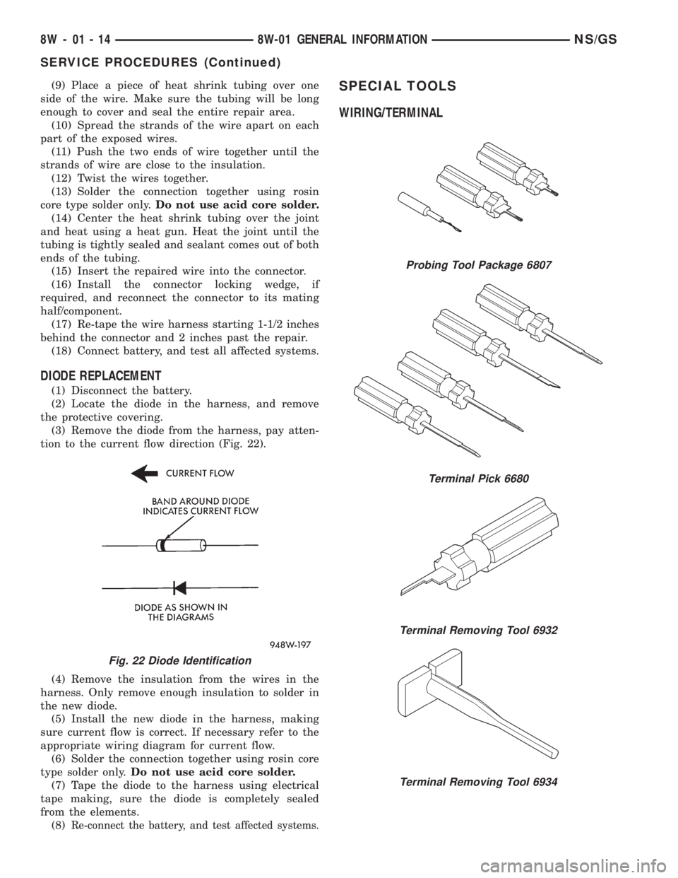
tion to the current flow direction (Fig. 22).
(4) Remove the insulation from the wires in the
harness. Only remove enough insulation to solder in
the new diode.
(5) Install the new diode in the harness, making
sure current flow is correct. If necessary refer to the
appropriate wiring diagram for current flow.
(6) Solder the connection together using rosin core
type solder only.Do not use acid core solder.
(7) Tape the diode to the harness using electrical
tape making, sure the diode is completely sealed
from the elements.
(8)
Re-connect the battery, and test affected systems.
SPECIAL TOOLS
WIRING/TERMINAL
Fig. 22 Diode Identification
Probing Tool Package 6807
Terminal Pick 6680
Terminal Removing Tool 6932
Terminal Removing Tool 6934
8W - 01 - 14 8W-01 GENERAL INFORMATIONNS/GS
SERVICE PROCEDURES (Continued)
Page 1025 of 1938
8W-95 SPLICE LOCATIONS
INDEX
page page
DESCRIPTION AND OPERATION
INTRODUCTION......................... 1SPLICE LOCATION INDEX.................. 1
SPLICE LOCATIONS (RHD)................ 15
DESCRIPTION AND OPERATION
INTRODUCTION
This section provides illustrations identifying the
general location of the splices in this vehicle. A spliceindex is provided. Use the wiring diagrams in each
section for splice number identification. Refer to the
index for the proper splice number.
SPLICE LOCATION INDEX
Splice Number Location Fig.
BS01 Near Split for Tail Lamps 12
BS02 Near Fuel Tank T/O 12
BS03 Near Instrument Panel T/O 9
BS05 Near Instrument Panel T/O 9
BS05 (2.5L) Near MSA Controller T/O N/S
BS06 Near Instrument Panel T/O 9
BS06 (2.5L) Near MSA Controller T/O N/S
BS08 Near Instrument Panel T/O 9
BS16 Near Right Park Lamp T/O 1
BS17 Near Split for Tail Lamps 12
BS19 Near Horn T/O 1
BS30 (2.5L) Near Generator T/O 5
BS31 Near Left Headlamp Leveling
Motor T/O1
BS31 (2.5L) In BCM T/O 5
BS32 (2.5L) In BCM T/O N/S
BS33 (2.5L) In BCM T/O N/S
BS34 (2.5L) In BCM T/O N/S
BS40 (2.5L) In Engine Harness T/O 5
BS41 (2.5L) In Engine Harness T/O N/S
CS01 Above Right Rear Door 11
CS02 Above Right Rear Door 11
CS03 Right B-Pillar 11
CS04 Right B-Pillar 11
DS01 Near LT Power WDO T/O 10
ES01 In TCM T/O 7
ES01 (2.5L) Near Battery Positive Terminal
T/ON/SSplice Number Location Fig.
ES02 (2.0L) Near Camshaft Position
Sensor T/O3
ES02 (2.4L) Near Fuel Rail T/O 4
ES02 (2.5L) Near Engine Speed Sensor
T/O5
ES02
(3.3L,3.8L)Near Transmission T/O 6
ES03 (2.0L) Near Distributor Coil T/O 2
ES03 (2.4L) Near PDC T/O 4
ES03
(3.3L,3.8L)Near Body Ground T/O 7
ES05 (2.4L) Near Knock Sensor T/O 4
ES05 (2.5L) In Fuel Injection Pump T/O 5
ES05
(3.3L,3.8L)Near Transmission T/O 6
ES06 (2.5L) Near Needle Movement
Sensor T/O5
ES06
(3.3L,3.8L)Near Transmission T/O N/S
ES07 (2.0L) Near Engine Ground T/O 2
ES07 (2.5L) Near Battery Negative
Terminal T/ON/S
ES07 (2.4L) Near Body Ground T/O 4, 7
ES07
(3.3L,3.8L)Near Battery Negative
Terminal T/O6
ES08
(3.3L,3.8L)Near Transmission T/O 6
ES09 (2.0L) In Battery Positive Terminal
T/O7
ES09 (2.4L) Near Battery Positive Terminal 4
NS/GS8W - 95 SPLICE LOCATIONS 8W - 95 - 1
Page 1303 of 1938
FUEL LEVEL SENSOR
This procedure tests the resistance of the level sen-
sor itself. It does not test the level sensor circuit.
Refer to Group 8W - Wiring Diagrams for circuit
identification.
The level sensor is a variable resistor. Its resis-
tance changes with the amount of fuel in the tank.
The float arm attached to the sensor moves as the
fuel level changes. To test the level sensor, connect
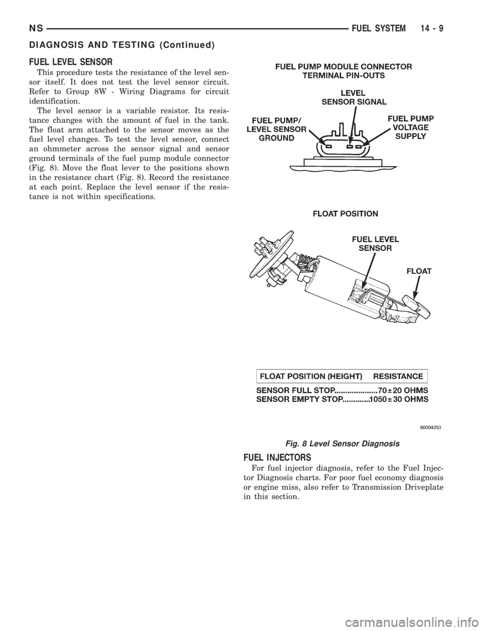
an ohmmeter across the sensor signal and sensor
ground terminals of the fuel pump module connector
(Fig. 8). Move the float lever to the positions shown
in the resistance chart (Fig. 8). Record the resistance
at each point. Replace the level sensor if the resis-
tance is not within specifications.
FUEL INJECTORS
For fuel injector diagnosis, refer to the Fuel Injec-
tor Diagnosis charts. For poor fuel economy diagnosis
or engine miss, also refer to Transmission Driveplate
in this section.
Fig. 8 Level Sensor Diagnosis
NSFUEL SYSTEM 14 - 9
DIAGNOSIS AND TESTING (Continued)
Page 1336 of 1938

in the engine compartment next to the battery (Fig.
30). A label affixed to the underside of the PDC cover
identifies the relays and fuses in the PDC.
GENERATOR FIELDÐPCM OUTPUT
The PCM regulates the charging system voltage
within a range of 12.9 to 15.0 volts. Refer to Group
8A for Battery system information and 8C for charg-
ing system information.
AUTOMATIC SHUTDOWN RELAYÐPCM OUTPUT
The Automatic Shutdown (ASD) relay supplies bat-
tery voltage to the fuel injectors, electronic ignition
coil and the heating elements in the oxygen sensors.
A buss bar in the Power Distribution Center (PDC)
supplies voltage to the solenoid side and contact side
of the relay. The ASD relay power circuit contains a
25 amp fuse between the buss bar in the PDC and
the relay. The fuse is located in the PDC. Refer to
Group 8W, Wiring Diagrams for circuit information.
The PCM controls the relay by switching the
ground path for the solenoid side of the relay on and
off. The PCM turns the ground path off when the
ignition switch is in the Off position unless the 02
Heater Monitor test is being run. Refer to Group 25,
On-Board Diagnostics. When the ignition switch is in
the On or Crank position, the PCM monitors the
crankshaft position sensor and camshaft position sen-
sor signals to determine engine speed and ignition
timing (coil dwell). If the PCM does not receive the
crankshaft position sensor and camshaft position sen-
sor signals when the ignition switch is in the Run
position, it will de-energize the ASD relay.The ASD relay is located in the PDC (Fig. 30). A
label affixed to the underside of the PDC cover iden-
tifies the relays and fuses in the PDC.
FUEL PUMP RELAYÐPCM OUTPUT
The fuel pump relay supplies battery voltage to the
fuel pump. The fuel pump relay power circuit con-
tains a 9 amp fuse. The fuse is located in the PDC.
Refer to Group 8W, Wiring Diagrams for circuit infor-
mation.
The PCM controls the fuel pump relay by switch-
ing the ground path for the solenoid side of the relay
on and off. The PCM turns the ground path off when
the ignition switch is in the Off position. When the
ignition switch is in the On position, the PCM ener-
gizes the fuel pump. If the crankshaft position sensor
does not detect engine rotation, the PCM de-ener-
gizes the relay after approximately one second.
The fuel pump relay is located in the PDC (Fig.
30). A label affixed to the underside of the PDC cover
identifies the relays and fuses in the PDC.
STARTER RELAYÐPCM OUTPUT
Double Start Override ia a feature that prevents
the starter from operating if the engine is already
running. This feature is accomplished with software
only. There was no hardware added because of this
feature. To incorporate the unique feature of Double
Start Override, it was necessary to use the PCM
(software) to control the starter circuit. To use the
PCM it was necessary to separate the starter relay
coil ground from the park neutral switch. The starter
relay ground is now controlled through Pin 60 of the
PCM. This allows the PCM to interrupt the ground
circuit if other inputs tell it that the engine is turn-
ing. If the starter system is operating properly, it can
be assumed that the override protection is also work-
ing.
IDLE AIR CONTROL MOTORÐPCM OUTPUT
The idle air control motor is mounted on the throt-
tle body. The PCM operates the idle air control motor
(Fig. 26) or (Fig. 27) or (Fig. 28). The PCM adjusts
engine idle speed through the idle air control motor
to compensate for engine load or ambient conditions.
The throttle body has an air bypass passage that
provides air for the engine at idle (the throttle blade
is closed). The idle air control motor pintle protrudes
into the air bypass passage and regulates air flow
through it.
The PCM adjusts engine idle speed by moving the
idle air control motor pintle in and out of the bypass
passage. The adjustments are based on inputs the
PCM receives. The inputs are from the throttle posi-
tion sensor, crankshaft position sensor, coolant tem-
perature sensor, and various switch operations
Fig. 30 Power Distribution Center (PDC)
14 - 42 FUEL SYSTEMNS
DESCRIPTION AND OPERATION (Continued)
Page 1355 of 1938
PCM. If OK, replace MAP sensor. If not OK, repair or
replace the wire harness as required.
HEATED OXYGEN SENSOR
Use an ohmmeter to test the heating element of
the oxygen sensors. Disconnect the electrical connec-
tor from each oxygen sensor. The white wires in the
sensor connector are the power and ground circuits
for the heater. Connect the ohmmeter test leads to
terminals of the white wires in the heated oxygen
sensor connector. Replace the heated oxygen sensor if
the resistance is not between 4 and 7 ohms.
KNOCK SENSOR
The engine knock sensor is affected by a number of
factors. A few of these are: ignition timing, cylinder
pressure, fuel octane, etc. The knock sensor gener-
ates an AC voltage whose amplitude increases with
the increase of engine knock. The knock sensor can
be tested with a digital voltmeter. The RMS voltage
starts at about 20mVac (at about 700 rpm) and
increases to approximately 600 mVac (5000 rpm). If
the output falls outside of this range a DTC will be
set.
CAMSHAFT AND CRANKSHAFT POSITION SENSOR
Refer to Group 8D, Ignition for Diagnosis and Test-
ing of Camshaft and Crankshaft Sensors.
ENGINE COOLANT TEMPERATURE SENSOR
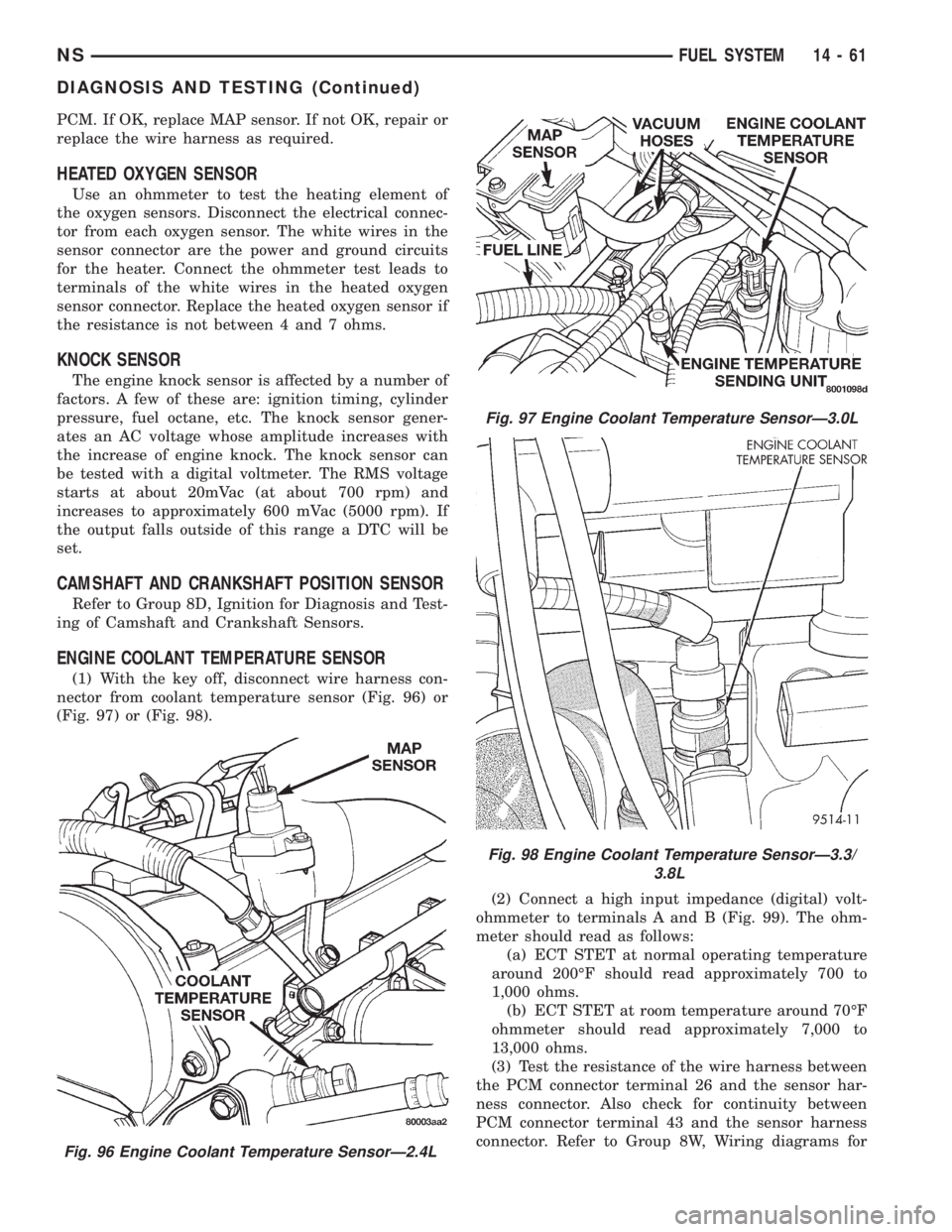
(1) With the key off, disconnect wire harness con-
nector from coolant temperature sensor (Fig. 96) or
(Fig. 97) or (Fig. 98).
(2) Connect a high input impedance (digital) volt-
ohmmeter to terminals A and B (Fig. 99). The ohm-
meter should read as follows:
(a) ECT STET at normal operating temperature
around 200ÉF should read approximately 700 to
1,000 ohms.
(b) ECT STET at room temperature around 70ÉF
ohmmeter should read approximately 7,000 to
13,000 ohms.
(3) Test the resistance of the wire harness between
the PCM connector terminal 26 and the sensor har-
ness connector. Also check for continuity between
PCM connector terminal 43 and the sensor harness
connector. Refer to Group 8W, Wiring diagrams for
Fig. 96 Engine Coolant Temperature SensorÐ2.4L
Fig. 97 Engine Coolant Temperature SensorÐ3.0L
Fig. 98 Engine Coolant Temperature SensorÐ3.3/
3.8L
NSFUEL SYSTEM 14 - 61
DIAGNOSIS AND TESTING (Continued)
Page 1421 of 1938
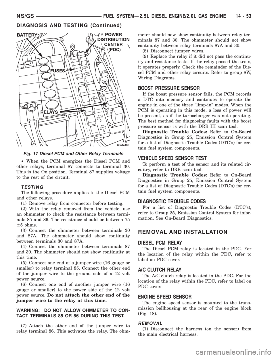
²When the PCM energizes the Diesel PCM and
other relays, terminal 87 connects to terminal 30.
This is the On position. Terminal 87 supplies voltage
to the rest of the circuit.
TESTING
The following procedure applies to the Diesel PCM
and other relays.
(1) Remove relay from connector before testing.
(2) With the relay removed from the vehicle, use
an ohmmeter to check the resistance between termi-
nals 85 and 86. The resistance should be between 75
65 ohms.
(3) Connect the ohmmeter between terminals 30
and 87A. The ohmmeter should show continuity
between terminals 30 and 87A.
(4) Connect the ohmmeter between terminals 87
and 30. The ohmmeter should not show continuity at
this time.
(5) Connect one end of a jumper wire (16 gauge or
smaller) to relay terminal 85. Connect the other end
of the jumper wire to the ground side of a 12 volt
power source.
(6) Connect one end of another jumper wire (16
gauge or smaller) to the power side of the 12 volt
power source.Do not attach the other end of the
jumper wire to the relay at this time.
WARNING: DO NOT ALLOW OHMMETER TO CON-
TACT TERMINALS 85 OR 86 DURING THIS TEST.
(7) Attach the other end of the jumper wire to
relay terminal 86. This activates the relay. The ohm-meter should now show continuity between relay ter-
minals 87 and 30. The ohmmeter should not show
continuity between relay terminals 87A and 30.
(8) Disconnect jumper wires.
(9) Replace the relay if it did not pass the continu-
ity and resistance tests. If the relay passed the tests,
it operates properly. Check the remainder of the Die-
sel PCM and other relay circuits. Refer to group 8W,
Wiring Diagrams.
BOOST PRESSURE SENSOR
If the boost pressure sensor fails, the PCM records
a DTC into memory and continues to operate the
engine in one of the three ªlimp-inº modes. When the
PCM is operating in this mode, a loss of power will
be present, as if the turbocharger was not operating.
The best method for diagnosing faults with the boost
pressure sensor is with the DRB III scan tool.
Diagnostic Trouble Codes:Refer to On-Board
Diagnostics in Group 25, Emission Control System
for a list of Diagnostic Trouble Codes (DTC's) for cer-
tain fuel system components.
VEHICLE SPEED SENSOR TEST
To perform a test of the sensor and its related cir-
cuitry, refer to DRB scan tool.
Diagnostic Trouble Codes:Refer to On-Board
Diagnostics in Group 25, Emission Control System
for a list of Diagnostic Trouble Codes (DTC's) for cer-
tain fuel system components.
DIAGNOSTIC TROUBLE CODES
For a list of Diagnostic Trouble Codes (DTC's),
refer to Group 25, Emission Control System for infor-
mation. See On-Board Diagnostics.
REMOVAL AND INSTALLATION
DIESEL PCM RELAY
The Diesel PCM relay is located in the PDC. For
the location of the relay within the PDC, refer to
label on PDC cover.
A/C CLUTCH RELAY
The A/C clutch relay is located in the PDC. For the
location of the relay within the PDC, refer to label on
PDC cover.
ENGINE SPEED SENSOR
The engine speed sensor is mounted to the trans-
mission bellhousing at the rear of the engine block
(Fig. 18).
REMOVAL
(1) Disconnect the harness (on the sensor) from
the main electrical harness.
Fig. 17 Diesel PCM and Other Relay Terminals
NS/GSFUEL SYSTEMÐ2.5L DIESEL ENGINE/2.0L GAS ENGINE 14 - 53
DIAGNOSIS AND TESTING (Continued)
Page 1475 of 1938
TRANSAXLE AND POWER TRANSFER UNIT
CONTENTS
page page
31TH AUTOMATIC TRANSAXLE.............. 1
41TE AUTOMATIC TRANSAXLE............. 71POWER TRANSFER UNIT................. 165
31TH AUTOMATIC TRANSAXLE
INDEX
page page
GENERAL INFORMATION
31TH TRANSAXLE........................ 2
FLUID LEVEL AND CONDITION.............. 2
SELECTION OF LUBRICANT................ 3
SPECIAL ADDITIVES...................... 3
DESCRIPTION AND OPERATION
CLUTCHES, BAND SERVOS, AND
ACCUMULATOR
...................... 3
FLOW CONTROL VALVES.................. 3
GEARSHIFT AND PARKING LOCK CONTROLS . . 4
GOVERNOR............................. 4
HYDRAULIC CONTROL SYSTEM............. 3
PRESSURE REGULATING VALVES........... 3
PRESSURE SUPPLY SYSTEM............... 3
TORQUE CONVERTER CLUTCH SOLENOID
WIRING CONNECTOR................... 4
TORQUE CONVERTER CLUTCH............. 3
DIAGNOSIS AND TESTING
CLUTCH AND SERVO AIR PRESSURE TESTS . 15
FLUID LEAKAGE-TRANSAXLE TORQUE
CONVERTER HOUSING AREA............ 15
HYDRAULIC PRESSURE TESTS............ 13
ROAD TEST............................. 4
THREE SPEED TRANSAXLE DIAGNOSIS AND
TESTS............................... 4
SERVICE PROCEDURES
ALUMINUM THREAD REPAIR.............. 18
FLUID AND FILTER CHANGE............... 16
FLUID DRAIN AND REFILL................. 18
FLUSHING COOLERS AND TUBES.......... 18
OIL PUMP VOLUME CHECK............... 19
REMOVAL AND INSTALLATION
FRONT PUMP OIL SEAL.................. 21
PARK/NEUTRAL STARTING AND BACK-UP
LAMP SWITCH........................ 19
TRANSAXLE AND TORQUE CONVERTER
REMOVAL............................ 20
VEHICLE SPEED SENSOR PINION GEAR..... 19DISASSEMBLY AND ASSEMBLY
ACCUMULATOR-RECONDITION............ 36
DIFFERENTIAL REPAIR................... 46
FRONT CLUTCH-RECONDITION............ 32
FRONT PLANETARY & ANNULUS GEAR-
RECONDITION........................ 35
KICKDOWN SERVO (CONTROLLED LOAD)-
RECONDITION........................ 37
LOW/REVERSE (REAR)
SERVO-RECONDITION.................. 36
OIL PUMP-RECONDITION................. 31
OUTPUT SHAFT REPAIR.................. 43
PARKING PAWL......................... 42
REAR CLUTCH-RECONDITION............. 33
TRANSAXLE........................... 21
TRANSFER SHAFT REPAIR................ 38
VALVE BODY RECONDITION............... 27
CLEANING AND INSPECTION
VALVE BODY........................... 50
ADJUSTMENTS
BAND ADJUSTMENT..................... 51
BEARING ADJUSTMENT PROCEDURES...... 52
DIFFERENTIAL BEARING................. 53
GEARSHIFT CABLE ADJUSTMENT.......... 51
HYDRAULIC CONTROL PRESSURE
ADJUSTMENTS....................... 52
OUTPUT SHAFT BEARING................ 52
THROTTLE PRESSURE LINKAGE
ADJUSTMENT......................... 51
TRANSFER SHAFT BEARING.............. 54
SCHEMATICS AND DIAGRAMS
31TH TRANSAXLE HYDRAULIC SCHEMATIC . . 56
SPECIFICATIONS
31TH AUTOMATIC TRANSAXLE............. 64
31TH TORQUE SPECIFICATIONS........... 65
SPECIAL TOOLS
31TH AUTOMATIC TRANSAXLE............. 66
NSTRANSAXLE AND POWER TRANSFER UNIT 21 - 1
Page 1822 of 1938

CAUTION: The refrigerant oil used in a R-134a A/C
system is unique. Use only oils which were
designed to work with R-134a refrigerant. The oil
designated for this vehicle is ND8 PAG (polyalka-
lene glycol).
SERVICING REFRIGERANT OIL LEVEL
(1) Using a refrigerant recovery machine, remove
refrigerant from the A/C system.
(2) Remove refrigerant lines from A/C compressor.
(3) Remove compressor from vehicle.
(4) From suction port on top of compressor, drain
refrigerant oil from compressor.
(5) Add system capacity minus the capacity of
components that have not been replaced through suc-
tion port on compressor. Refer to the Refrigerant Oil
Capacity Chart.
(6) Install compressor, connect refrigerant lines,
evacuate, and charge refrigerant system.
DIAGNOSIS AND TESTING
ACTUATOR CALIBRATION/DIAGNOSTICS AND
COOLDOWN TEST
GENERAL INFORMATION
If the HVAC control module is replaced, the Cali-
bration Diagnostic and Cooldown tests will need to
be performed. Once this group of tests have success-
fully passed, they can be performed individually. The
engine must be running during the test to provide
hot coolant for the heater, A/C compressor operation
and to assure that the actuators are calibrated cor-
rectly. The HVAC control module is capable of trou-
bleshooting the system in approximately 120 seconds.
If a condition is detected, an error code is displayed.
The error code cannot be erased until the condition is
repaired and the diagnostic test is performed. Check
wire before replacing components, refer to Group 8W,
Wiring Diagrams.CAUTION: Do not remove the actuators from the
Heater-A/C unit assembly with power applied.
Removal should only be done with the Ignition OFF.
The actuators have no mechanical stops to limit the
travel. If the actuator rotates and is not connected
to the unit assembly, it will become out of calibra-
tion.
ACTUATOR CALIBRATION
Mode, Blend and Zone (if equipped) door calibra-
tion compensates for mechanical variations in the
actuators, HVAC control module and its linkages. In-
vehicle calibration can be entered from the control's
front panel. If the REAR WIPE and INTERMIT-
TENT LED's flash simultaneously when Ignition is
cycled ON, the actuators have not been calibrated or
during the previous calibration a failure occurred
(Fig. 6) and (Fig. 7). Diagnostics will always occur
during Calibration Diagnostic and Cooldown test.
REFRIGERANT OIL CAPACITIES
Refrigerant
Oil Capaci-
tiesFront A/C Dual A/C
Component ml oz ml oz
Compressor 150 ml 5.0 oz 220 ml 7.4 oz
Filter-Drier 30 ml 1.0 oz 30 ml 1.0 oz
Condenser 30 ml 1.0 oz 30 ml 1.0 oz
Evaporator 60 ml 2.0 oz 60 ml 2 .0 oz
Rear Evap. N/A N/A 60 ml 2.0 oz
Fig. 6 Radio Bezel and HVAC Control
24 - 6 HEATING AND AIR CONDITIONINGNS
DESCRIPTION AND OPERATION (Continued)