1996 CHRYSLER VOYAGER air filter
[x] Cancel search: air filterPage 1828 of 1938
probe will drop the temperature 7ÉC (20ÉF) in two
minutes. If the Evaporator Probe is found to be
faulty, check that the sensor is positioned in the
evaporator fins properly. If not, correct and repeat
test. If OK, replace the evaporator probe.
Once the repairs are completed, repeat the Calibra-
tion Diagnostic and Cooldown test. Repeating the
test is necessary to clear the fault codes.
A/C PERFORMANCE TEST
The air conditioning system is designed to remove
heat and humidity from the air entering the passen-
ger compartment. The evaporator, located in the
heater A/C unit, is cooled to temperatures near the
freezing point. As warm damp air passes over the
fins in the evaporator, moisture in the air condenses
to water, dehumidifying the air. Condensation on the
evaporator fins reduces the evaporators ability to
absorb heat. During periods of high heat and humid-
ity, an air conditioning system will be less effective.
With the instrument control set to RECIRC, only air
from the passenger compartment passes through the
evaporator. As the passenger compartment air dehu-
midifies, A/C performance levels rise.
PERFORMANCE TEST PROCEDURE
Review Safety Precautions and Warnings in this
group before proceeding with this procedure. Air tem-
perature in test room and on vehicle must be 21É C
(70ÉF) minimum for this test.
NOTE: When connecting the service equipment
coupling to the line fitting, verify that the valve of
the coupling is fully closed. This will reduce the
amount of effort required to make the connection.
(1) Connect a tachometer and manifold gauge set.
(2) Set control to A/C, RECIRC, and PANEL, tem-
perature lever on full cool and blower on high.
(3) Start engine and hold at 1000 rpm with A/C
clutch engaged.(4) Engine should be warmed up with doors and
windows closed.
(5) Insert a thermometer in the left center A/C
outlet and operate the engine for five minutes. The
A/C clutch may cycle depending on ambient condi-
tions.
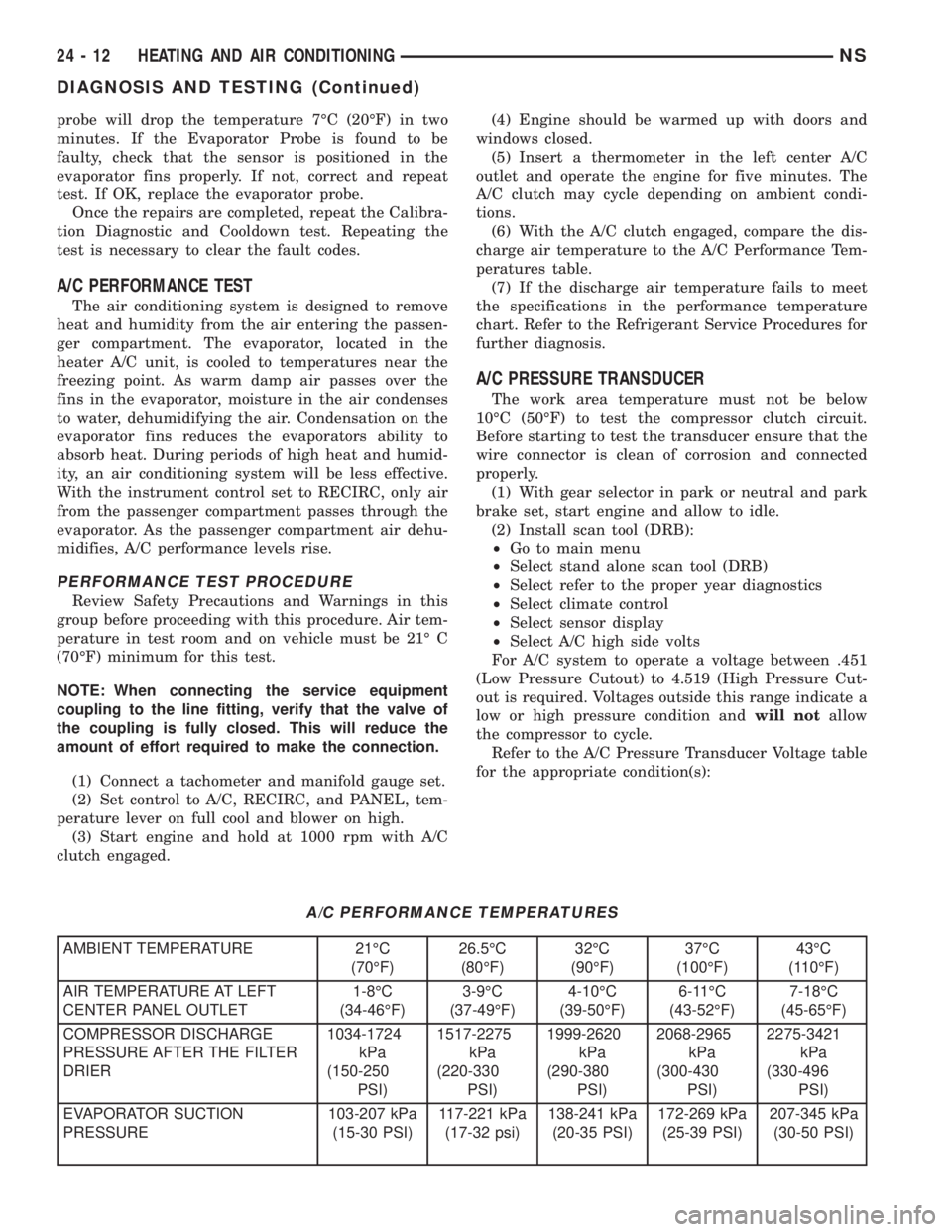
(6) With the A/C clutch engaged, compare the dis-
charge air temperature to the A/C Performance Tem-
peratures table.
(7) If the discharge air temperature fails to meet
the specifications in the performance temperature
chart. Refer to the Refrigerant Service Procedures for
further diagnosis.
A/C PRESSURE TRANSDUCER
The work area temperature must not be below
10ÉC (50ÉF) to test the compressor clutch circuit.
Before starting to test the transducer ensure that the
wire connector is clean of corrosion and connected
properly.
(1) With gear selector in park or neutral and park
brake set, start engine and allow to idle.
(2) Install scan tool (DRB):
²Go to main menu
²Select stand alone scan tool (DRB)
²Select refer to the proper year diagnostics
²Select climate control
²Select sensor display
²Select A/C high side volts
For A/C system to operate a voltage between .451
(Low Pressure Cutout) to 4.519 (High Pressure Cut-
out is required. Voltages outside this range indicate a
low or high pressure condition andwill notallow
the compressor to cycle.
Refer to the A/C Pressure Transducer Voltage table
for the appropriate condition(s):
A/C PERFORMANCE TEMPERATURES
AMBIENT TEMPERATURE 21ÉC
(70ÉF)26.5ÉC
(80ÉF)32ÉC
(90ÉF)37ÉC
(100ÉF)43ÉC
(110ÉF)
AIR TEMPERATURE AT LEFT
CENTER PANEL OUTLET1-8ÉC
(34-46ÉF)3-9ÉC
(37-49ÉF)4-10ÉC
(39-50ÉF)6-11ÉC
(43-52ÉF)7-18ÉC
(45-65ÉF)
COMPRESSOR DISCHARGE
PRESSURE AFTER THE FILTER
DRIER1034-1724
kPa
(150-250
PSI)1517-2275
kPa
(220-330
PSI)1999-2620
kPa
(290-380
PSI)2068-2965
kPa
(300-430
PSI)2275-3421
kPa
(330-496
PSI)
EVAPORATOR SUCTION
PRESSURE103-207 kPa
(15-30 PSI)117-221 kPa
(17-32 psi)138-241 kPa
(20-35 PSI)172-269 kPa
(25-39 PSI)207-345 kPa
(30-50 PSI)
24 - 12 HEATING AND AIR CONDITIONINGNS
DIAGNOSIS AND TESTING (Continued)
Page 1839 of 1938
COMPRESSOR
REMOVAL
WARNING: REFER TO REFRIGERANT SERVICE
PROCEDURES FOR INFORMATION REGARDING
PROPER RECOVERY OF THE REFRIGERANT
BEFORE ATTEMPTING TO REMOVE THE COM-
PRESSOR.
(1) Disconnect negative battery cable.
(2) Pinch off coolant lines to rear Heat unit (if
equipped). Drain engine coolant.
(3) Remove upper radiator hose.
(4) Remove drive belt (refer to Group 7, Cooling
System). Disconnect compressor clutch wire lead.
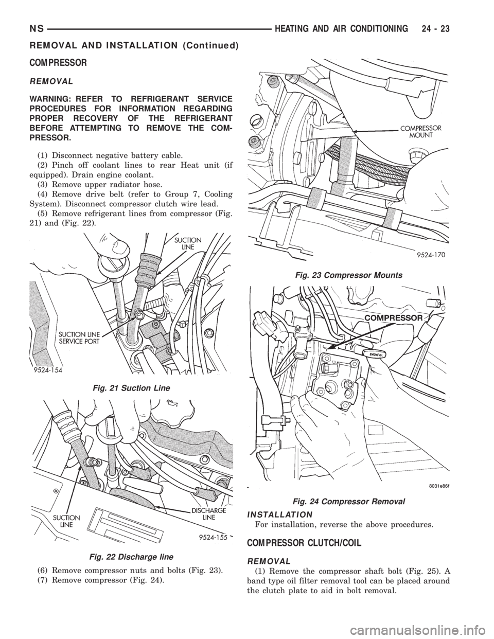
(5) Remove refrigerant lines from compressor (Fig.
21) and (Fig. 22).
(6) Remove compressor nuts and bolts (Fig. 23).
(7) Remove compressor (Fig. 24).
INSTALLATION
For installation, reverse the above procedures.
COMPRESSOR CLUTCH/COIL
REMOVAL
(1) Remove the compressor shaft bolt (Fig. 25). A
band type oil filter removal tool can be placed around
the clutch plate to aid in bolt removal.
Fig. 21 Suction Line
Fig. 22 Discharge line
Fig. 23 Compressor Mounts
Fig. 24 Compressor Removal
NSHEATING AND AIR CONDITIONING 24 - 23
REMOVAL AND INSTALLATION (Continued)
Page 1841 of 1938
CAUTION: The clutch pulley and the front plate
were mated at the factory by a burnishing opera-
tion. No attempt should be made to separately
replace either part. This will result in clutch slip-
page due to insufficient contact area.
INSTALLATION
(1) Align pin in back of field coil with hole in com-
pressor end housing, and position field coil into place.
Make sure that lead wires are properly routed, and
fasten with the wire clip screw.
(2) Install field coil retaining snap ring with snap
ring pliers. The bevel side of the snap ring facing
outward. Also both snap ring eyelets must be to the
right or left of the pin on compressor. Press snap ring
to make sure it is properly seated in the groove.
CAUTION: If snap ring is not fully seated it will
vibrate out, resulting in a clutch failure and severe
damage to the front face of the compressor.
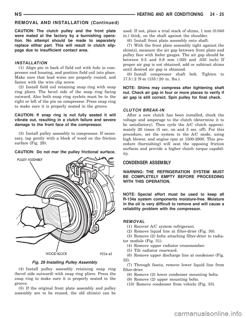
(3) Install pulley assembly to compressor. If neces-
sary, tap gently with a block of wood on the friction
surface (Fig. 29).
CAUTION: Do not mar the pulley frictional surface.
(4) Install pulley assembly retaining snap ring
(bevel side outward) with snap ring pliers. Press the
snap ring to make sure it is properly seated in the
groove.
(5) If the original front plate assembly and pulley
assembly are to be reused, the old shim(s) can beused. If not, place a trial stack of shims, 1 mm (0.040
in.) thick, on the shaft against the shoulder.
(6) Install front plate assembly onto shaft.
(7) With the front plate assembly tight against the
shim(s), measure the air gap between front plate and
pulley face with feeler gauges. The air gap should be
between 0.5 and 0.9 mm (.020 and .035 inch) If
proper air gap is not obtained, add or subtract shims
until desired air gap is obtained.
(8) Install compressor shaft bolt. Tighten to
17.562 N´m (155620 in. lbs.).
NOTE: Shims may compress after tightening shaft
nut. Check air gap in four or more places to verify if
air gap is still correct. Spin pulley for final check.
CLUTCH BREAK-IN
After a new clutch has been installed, check the
voltage and amperage to the clutch (determine it to
be satisfactory). Then cycle the A/C clutch approxi-
mately 20 times (5 sec. on and 5 sec. off). For this
procedure, set the system to the A/C mode, using
high blower, and engine rpm at 1500-2000. This pro-
cedure (burnishing) will seat the opposing friction
surfaces and provide a higher clutch torque capabil-
ity.
CONDENSER ASSEMBLY
WARNING: THE REFRIGERATION SYSTEM MUST
BE COMPLETELY EMPTY BEFORE PROCEEDING
WITH THIS OPERATION.
NOTE: Special effort must be used to keep all
R-134a system components moisture-free. Moisture
in the oil is very difficult to remove and will cause a
reliability problem with the compressor.
REMOVAL
(1) Recover A/C system refrigerant.
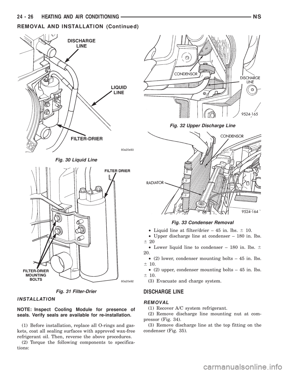
(2) Remove liquid line at filter-drier (Fig. 30).
(3) Remove (2) bolts attaching filter-drier to radia-
tor module (Fig. 31).
(4) Remove upper radiator crossmember.
(5) Tilt radiator rearward.
(6) Remove upper discharge line at condenser (Fig.
32).
(7) Through fascia, remove lower liquid line from
filter-drier.
(8) Remove (2) lower condenser mounting bolts.
(9) Remove (2) upper mounting bolts.
(10) Remove condenser from vehicle (Fig. 33).
Fig. 29 Installing Pulley Assembly
NSHEATING AND AIR CONDITIONING 24 - 25
REMOVAL AND INSTALLATION (Continued)
Page 1842 of 1938
INSTALLATION
NOTE: Inspect Cooling Module for presence of
seals. Verify seals are available for re-installation.
(1) Before installation, replace all O-rings and gas-
kets, coat all sealing surfaces with approved wax-free
refrigerant oil. Then, reverse the above procedures.
(2) Torque the following components to specifica-
tions:²Liquid line at filter/drier ± 45 in. lbs.610.
²Upper discharge line at condenser ± 180 in. lbs.
620
²Lower liquid line to condenser ± 180 in. lbs.6
20.
²(2) lower, condenser mounting bolts ± 45 in. lbs.
610.
²(2) upper, condenser mounting bolts ± 45 in. lbs.
610.
(3) Evacuate and charge system.
DISCHARGE LINE
REMOVAL
(1) Recover A/C system refrigerant.
(2) Remove discharge line mounting nut at com-
pressor (Fig. 34).
(3) Remove discharge line at the top fitting on the
condenser (Fig. 35).
Fig. 30 Liquid Line
Fig. 31 Filter-Drier
Fig. 32 Upper Discharge Line
Fig. 33 Condenser Removal
24 - 26 HEATING AND AIR CONDITIONINGNS
REMOVAL AND INSTALLATION (Continued)
Page 1844 of 1938
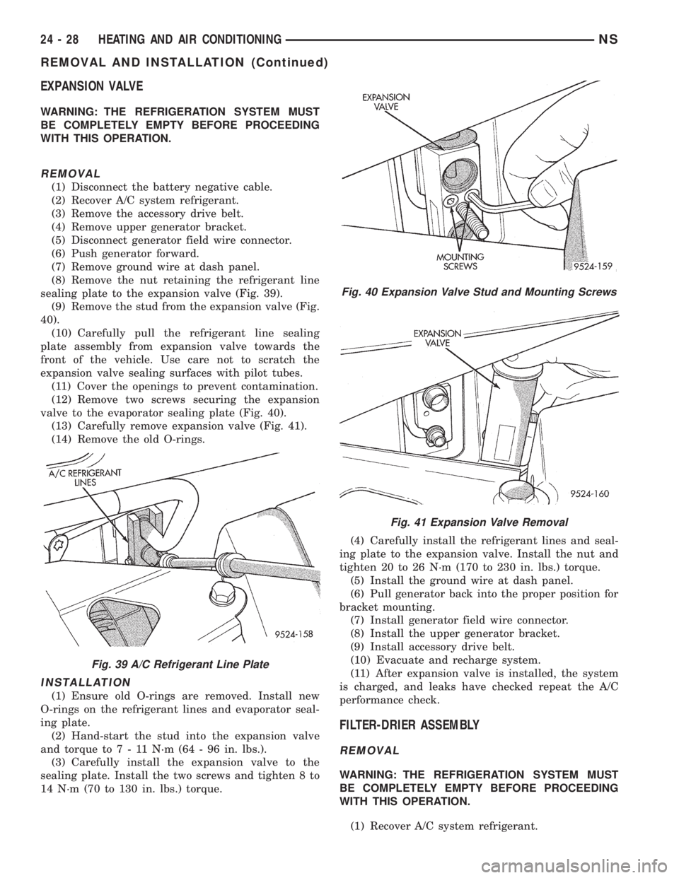
EXPANSION VALVE
WARNING: THE REFRIGERATION SYSTEM MUST
BE COMPLETELY EMPTY BEFORE PROCEEDING
WITH THIS OPERATION.
REMOVAL
(1) Disconnect the battery negative cable.
(2) Recover A/C system refrigerant.
(3) Remove the accessory drive belt.
(4) Remove upper generator bracket.
(5) Disconnect generator field wire connector.
(6) Push generator forward.
(7) Remove ground wire at dash panel.
(8) Remove the nut retaining the refrigerant line
sealing plate to the expansion valve (Fig. 39).
(9) Remove the stud from the expansion valve (Fig.
40).
(10) Carefully pull the refrigerant line sealing
plate assembly from expansion valve towards the
front of the vehicle. Use care not to scratch the
expansion valve sealing surfaces with pilot tubes.
(11) Cover the openings to prevent contamination.
(12) Remove two screws securing the expansion
valve to the evaporator sealing plate (Fig. 40).
(13) Carefully remove expansion valve (Fig. 41).
(14) Remove the old O-rings.
INSTALLATION
(1) Ensure old O-rings are removed. Install new
O-rings on the refrigerant lines and evaporator seal-
ing plate.
(2) Hand-start the stud into the expansion valve
and torque to7-11N´m(64-96in.lbs.).
(3) Carefully install the expansion valve to the
sealing plate. Install the two screws and tighten 8 to
14 N´m (70 to 130 in. lbs.) torque.(4) Carefully install the refrigerant lines and seal-
ing plate to the expansion valve. Install the nut and
tighten 20 to 26 N´m (170 to 230 in. lbs.) torque.
(5) Install the ground wire at dash panel.
(6) Pull generator back into the proper position for
bracket mounting.
(7) Install generator field wire connector.
(8) Install the upper generator bracket.
(9) Install accessory drive belt.
(10) Evacuate and recharge system.
(11) After expansion valve is installed, the system
is charged, and leaks have checked repeat the A/C
performance check.
FILTER-DRIER ASSEMBLY
REMOVAL
WARNING: THE REFRIGERATION SYSTEM MUST
BE COMPLETELY EMPTY BEFORE PROCEEDING
WITH THIS OPERATION.
(1) Recover A/C system refrigerant.
Fig. 39 A/C Refrigerant Line Plate
Fig. 40 Expansion Valve Stud and Mounting Screws
Fig. 41 Expansion Valve Removal
24 - 28 HEATING AND AIR CONDITIONINGNS
REMOVAL AND INSTALLATION (Continued)
Page 1845 of 1938
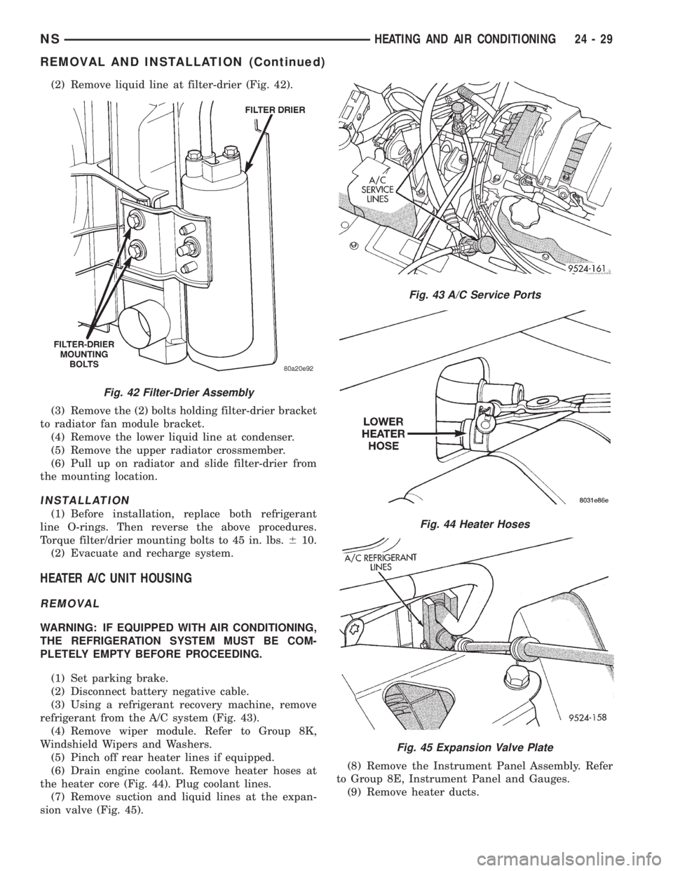
(2) Remove liquid line at filter-drier (Fig. 42).
(3) Remove the (2) bolts holding filter-drier bracket
to radiator fan module bracket.
(4) Remove the lower liquid line at condenser.
(5) Remove the upper radiator crossmember.
(6) Pull up on radiator and slide filter-drier from
the mounting location.
INSTALLATION
(1) Before installation, replace both refrigerant
line O-rings. Then reverse the above procedures.
Torque filter/drier mounting bolts to 45 in. lbs.610.
(2) Evacuate and recharge system.
HEATER A/C UNIT HOUSING
REMOVAL
WARNING: IF EQUIPPED WITH AIR CONDITIONING,
THE REFRIGERATION SYSTEM MUST BE COM-
PLETELY EMPTY BEFORE PROCEEDING.
(1) Set parking brake.
(2) Disconnect battery negative cable.
(3) Using a refrigerant recovery machine, remove
refrigerant from the A/C system (Fig. 43).
(4) Remove wiper module. Refer to Group 8K,
Windshield Wipers and Washers.
(5) Pinch off rear heater lines if equipped.
(6) Drain engine coolant. Remove heater hoses at
the heater core (Fig. 44). Plug coolant lines.
(7) Remove suction and liquid lines at the expan-
sion valve (Fig. 45).(8) Remove the Instrument Panel Assembly. Refer
to Group 8E, Instrument Panel and Gauges.
(9) Remove heater ducts.
Fig. 42 Filter-Drier Assembly
Fig. 43 A/C Service Ports
Fig. 44 Heater Hoses
Fig. 45 Expansion Valve Plate
NSHEATING AND AIR CONDITIONING 24 - 29
REMOVAL AND INSTALLATION (Continued)
Page 1848 of 1938
CAUTION: When removing hoses from heater core
inlet or outlet nipples, do not use excessive force.
Heater core may become damaged and leak engine
coolant.
(3) Carefully rotate hose back and forth while tug-
ging slightly away from connector nipple. If the hose
will not come off, slice the hose at the connector nip-
ple and peel off heater hose. This method will require
heater hose replacement.
INSTALLATION
For installation, reverse the above procedures.
LIQUID LINE
REMOVAL
(1) Disconnect the battery negative cable.
(2) Recover A/C system refrigerant.
(3) Remove the accessory drive belt.
(4) Remove upper generator bracket.
(5) Remove ground wire at dash panel.
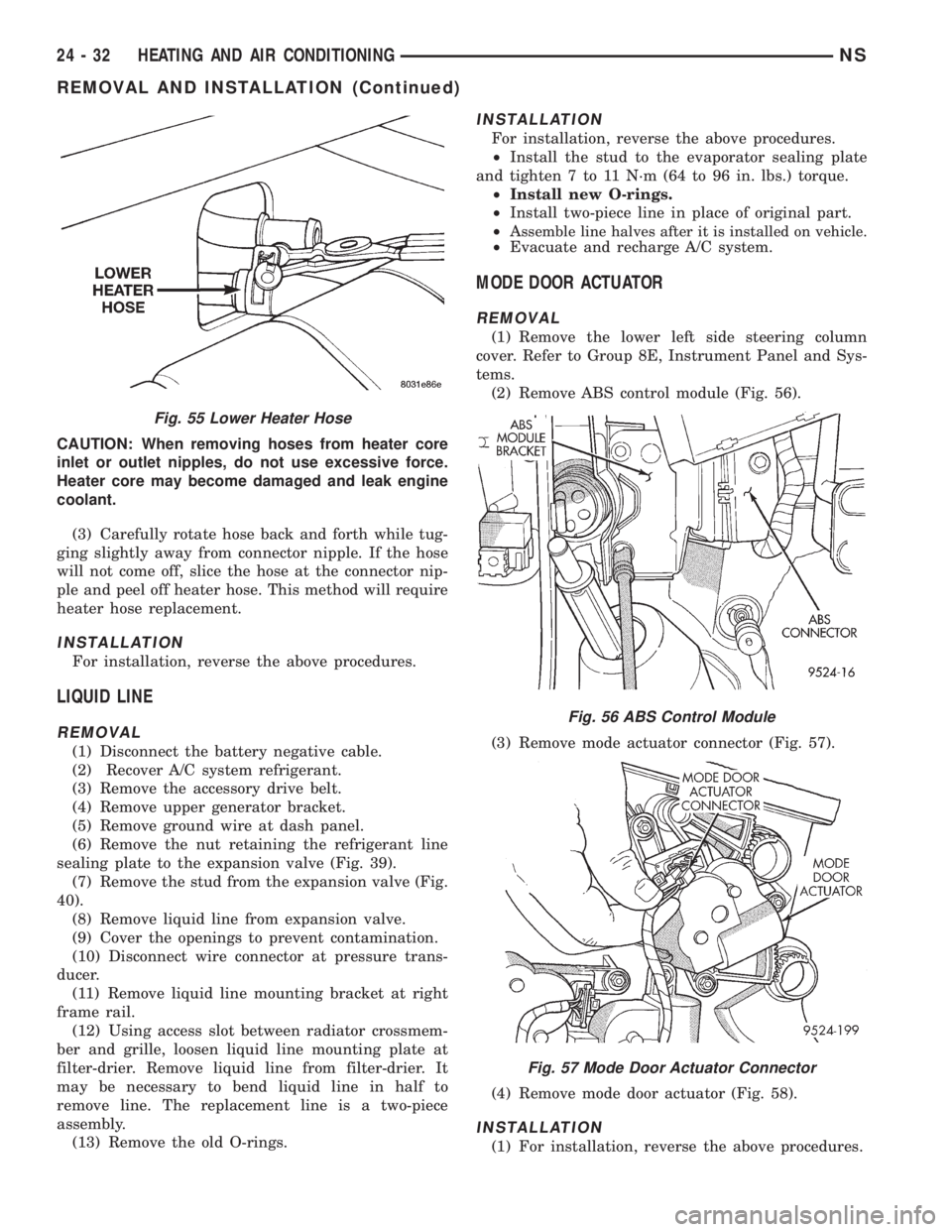
(6) Remove the nut retaining the refrigerant line
sealing plate to the expansion valve (Fig. 39).
(7) Remove the stud from the expansion valve (Fig.
40).
(8) Remove liquid line from expansion valve.
(9) Cover the openings to prevent contamination.
(10) Disconnect wire connector at pressure trans-
ducer.
(11) Remove liquid line mounting bracket at right
frame rail.
(12) Using access slot between radiator crossmem-
ber and grille, loosen liquid line mounting plate at
filter-drier. Remove liquid line from filter-drier. It
may be necessary to bend liquid line in half to
remove line. The replacement line is a two-piece
assembly.
(13) Remove the old O-rings.
INSTALLATION
For installation, reverse the above procedures.
²Install the stud to the evaporator sealing plate
and tighten 7 to 11 N´m (64 to 96 in. lbs.) torque.
²Install new O-rings.
²Install two-piece line in place of original part.
²A
ssemble line halves after it is installed on vehicle.²Evacuate and recharge A/C system.
MODE DOOR ACTUATOR
REMOVAL
(1) Remove the lower left side steering column
cover. Refer to Group 8E, Instrument Panel and Sys-
tems.
(2) Remove ABS control module (Fig. 56).
(3) Remove mode actuator connector (Fig. 57).
(4) Remove mode door actuator (Fig. 58).
INSTALLATION
(1) For installation, reverse the above procedures.
Fig. 55 Lower Heater Hose
Fig. 56 ABS Control Module
Fig. 57 Mode Door Actuator Connector
24 - 32 HEATING AND AIR CONDITIONINGNS
REMOVAL AND INSTALLATION (Continued)
Page 1867 of 1938
HEATING AND AIR CONDITIONING
CONTENTS
page page
GENERAL INFORMATION
INTRODUCTION........................ 1
SAFETY PRECAUTIONS AND WARNINGS.... 2
DESCRIPTION AND OPERATION
A/C PRESSURE TRANSDUCER............ 2
A/C SERVICE PORTS.................... 2
AIR DISTRIBUTION DUCTS............... 2
COMPRESSOR......................... 2
COMPRESSOR HIGH-PRESSURE RELIEF
VALVE .............................. 3
CONDENSATE DRAIN.................... 3
ENGINE COOLING SYSTEM REQUIREMENTS . 3
EVAPORATOR PROBE................... 3
HANDLING TUBING AND FITTINGS........ 3
HVAC CONTROL MODULE................ 3
SIDE DOOR HEATER A/C OUTLETS........ 4
SIDE WINDOW DEMISTER............... 4
SYSTEM AIRFLOW..................... 4
SYSTEM OIL LEVEL..................... 4
DIAGNOSIS AND TESTING
A/C PERFORMANCE TEST............... 11
A/C PRESSURE TRANSDUCER........... 11
ACTUATOR CALIBRATION/DIAGNOSTICS AND
COOLDOWN TEST..................... 5
BLOWER MOTOR AND WHEEL ASSEMBLY . 12
COMPRESSOR CLUTCH/COIL............ 12
COMPRESSOR NOISE DIAGNOSIS........ 12
EXPANSION VALVE.................... 14
HEATER PERFORMANCE TEST........... 14
HVAC CONTROL DIAGNOSTIC CONDITIONS . 9
SYSTEM CHARGE LEVEL TEST........... 15SERVICE PROCEDURES
CHARGING REFRIGERANT SYSTEM....... 17
EVACUATING REFRIGERANT SYSTEM..... 17
R-134a REFRIGERANT.................. 16
STICKING HVAC CONTROL MODULE PUSH
BUTTONS.......................... 18
SYSTEM LEAK CHECKING............... 19
THERMOCOUPLE PROBE............... 18
REMOVAL AND INSTALLATION
A/C PRESSURE TRANSDUCER........... 19
A/C SERVICE PORTS................... 19
BLEND-AIR DOOR ACTUATOR........... 20
BLOWER MOTOR AND WHEEL ASSEMBLY . 20
BLOWER MOTOR RESISTOR BLOCK...... 21
BLOWER MOTOR WHEEL............... 22
COMPRESSOR (2.5L TURBO DIESEL)..... 22
CONDENSER ASSEMBLY................ 23
DISCHARGE LINE..................... 23
EVAPORATOR PROBE.................. 24
EXPANSION VALVE.................... 25
FILTER-DRIER ASSEMBLY............... 26
HEATER A/C UNIT HOUSING............. 26
HEATER CORE........................ 26
HEATER HOSES....................... 28
LIQUID LINE......................... 28
MODE DOOR ACTUATOR................ 29
RECIRC DOOR ACTUATOR.............. 30
SIDE WINDOW DEMISTER DUCTS........ 29
SUCTION LINE........................ 29
DISASSEMBLY AND ASSEMBLY
HEATER A/C UNIT RECONDITION......... 30
GENERAL INFORMATION
INTRODUCTION
The Heater, or Heater and Air Conditioning sys-
tems share many of the same components. This
group will deal with both systems together when
component function is common, and separately when
they are not.
For proper operation of the instrument panel con-
trols, refer to the Owner's Manual provided with the
vehicle.All vehicles are equipped with a common Heater
A/C unit housing assembly. When the vehicle has
only a heater system, the evaporator and recirculat-
ing air door are omitted.
An optional zone control HVAC unit is available.
This unit has dual blend-air doors that can be regu-
lated independently of each other. The temperature
setting can be different from driver's side to passen-
ger side.
NS/GSHEATING AND AIR CONDITIONING 24 - 1