1996 CHRYSLER VOYAGER oil
[x] Cancel search: oilPage 1888 of 1938
(3) Remove resistor block by inserting a flat blade
pry tool on the side of the resistor block and pushing
inward. Two guide lines are shown on the right hand
edge of the resistor block to help guide the blade
position. This will release the clips on the side of the
resistor block. Pull resistor block out.
INSTALLATION
For installation, reverse the above procedures.
Make sure the ªTOPº lettering is on the top of the
resistor. The coils on the Resistor Block should not be
contacting one another. Before installation, gently
separate the coils (with fingers only) if one coil is
contacting another.
BLOWER MOTOR WHEEL
The blower motor wheel is not serviced separately.
If the wheel needs to be replaced it is serviced as an
assembly of the blower motor. For service procedure
information, refer to Blower Motor Replacement in
this group.
COMPRESSOR (2.5L TURBO DIESEL)
REMOVAL
WARNING: REFER TO REFRIGERANT SERVICE
PROCEDURES FOR INFORMATION REGARDING
PROPER RECOVERY OF THE REFRIGERANT
BEFORE ATTEMPTING TO REMOVE THE COM-
PRESSOR.(1) Disconnect negative battery cable.
(2) Reclaim refrigerant.
(3) Raise vehicle on hoist.
(4) Remove refrigerant lines from compressor and
cap all lines (Fig. 10).
(5) Remove flex drive bolts from behind the power
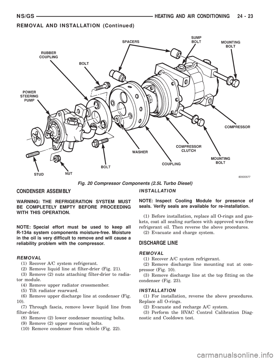
steering pump (Fig. 20).
(6) Remove compressor mounting bolts (Fig. 20).
(7) pry compressor off of the dowel pins and
remove compressor.
INSTALLATION
(1) Transfer mounting spacer/bushings onto the
new compressor.
(2) Lift compressor into place and start compressor
mounting bolts. Do not tighten bolts at this time. The
compressor may have to be moved slightly to align
the flex drive bolts.
(3) Align compressor clutch with flex drive. Then
start both flex drive bolts. Tighten the bolts after
both flex drive bolts have been installed.
(4) Tighten compressor mounting bolts.
(5) Lower vehicle and install refrigerant lines.
Always replace O-rings and gaskets.
(6) Evacuate refrigerant system. Charge system
with the correct amount of R-134a refrigerant. The
refrigerant capacity is .91 kg.67 gm. (32 oz.62.0
oz.).
24 - 22 HEATING AND AIR CONDITIONINGNS/GS
REMOVAL AND INSTALLATION (Continued)
Page 1889 of 1938
CONDENSER ASSEMBLY
WARNING: THE REFRIGERATION SYSTEM MUST
BE COMPLETELY EMPTY BEFORE PROCEEDING
WITH THIS OPERATION.
NOTE: Special effort must be used to keep all
R-134a system components moisture-free. Moisture
in the oil is very difficult to remove and will cause a
reliability problem with the compressor.
REMOVAL
(1) Recover A/C system refrigerant.
(2) Remove liquid line at filter-drier (Fig. 21).
(3) Remove (2) nuts attaching filter-drier to radia-
tor module.
(4) Remove upper radiator crossmember.
(5) Tilt radiator rearward.
(6) Remove upper discharge line at condenser (Fig.
10).
(7) Through fascia, remove lower liquid line from
filter-drier.
(8) Remove (2) lower condenser mounting bolts.
(9) Remove (2) upper mounting bolts.
(10) Remove condenser from vehicle (Fig. 22).
INSTALLATION
NOTE: Inspect Cooling Module for presence of
seals. Verify seals are available for re-installation.
(1) Before installation, replace all O-rings and gas-
kets, coat all sealing surfaces with approved wax-free
refrigerant oil. Then reverse the above procedures.
(2) Evacuate and charge system.
DISCHARGE LINE
REMOVAL
(1) Recover A/C system refrigerant.
(2) Remove discharge line mounting nut at com-
pressor (Fig. 10).
(3) Remove discharge line at the top fitting on the
condenser (Fig. 23).
INSTALLATION
(1) For installation, reverse the above procedures.
Replace all O-rings.
(2) Evacuate and recharge A/C system.
(3) Perform the HVAC Control Calibration Diag-
nostic and Cooldown test.
Fig. 20 Compressor Components (2.5L Turbo Diesel)
NS/GSHEATING AND AIR CONDITIONING 24 - 23
REMOVAL AND INSTALLATION (Continued)
Page 1898 of 1938
CAUTION: Do not damage the insulation barrier
surrounding the evaporator.
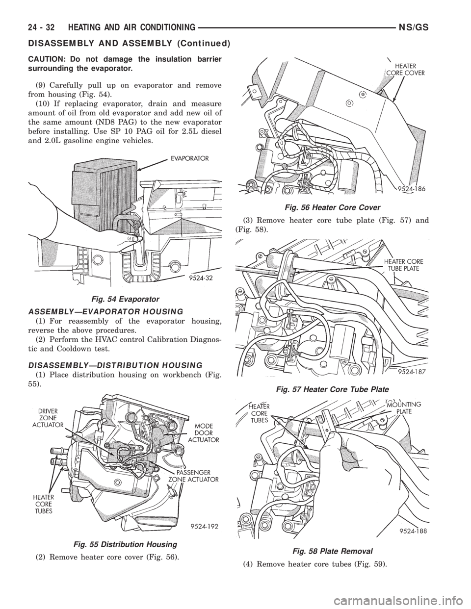
(9) Carefully pull up on evaporator and remove
from housing (Fig. 54).
(10) If replacing evaporator, drain and measure
amount of oil from old evaporator and add new oil of
the same amount (ND8 PAG) to the new evaporator
before installing. Use SP 10 PAG oil for 2.5L diesel
and 2.0L gasoline engine vehicles.
ASSEMBLYÐEVAPORATOR HOUSING
(1) For reassembly of the evaporator housing,
reverse the above procedures.
(2) Perform the HVAC control Calibration Diagnos-
tic and Cooldown test.
DISASSEMBLYÐDISTRIBUTION HOUSING
(1) Place distribution housing on workbench (Fig.
55).
(2) Remove heater core cover (Fig. 56).(3) Remove heater core tube plate (Fig. 57) and
(Fig. 58).
(4) Remove heater core tubes (Fig. 59).
Fig. 54 Evaporator
Fig. 55 Distribution Housing
Fig. 56 Heater Core Cover
Fig. 57 Heater Core Tube Plate
Fig. 58 Plate Removal
24 - 32 HEATING AND AIR CONDITIONINGNS/GS
DISASSEMBLY AND ASSEMBLY (Continued)
Page 1909 of 1938
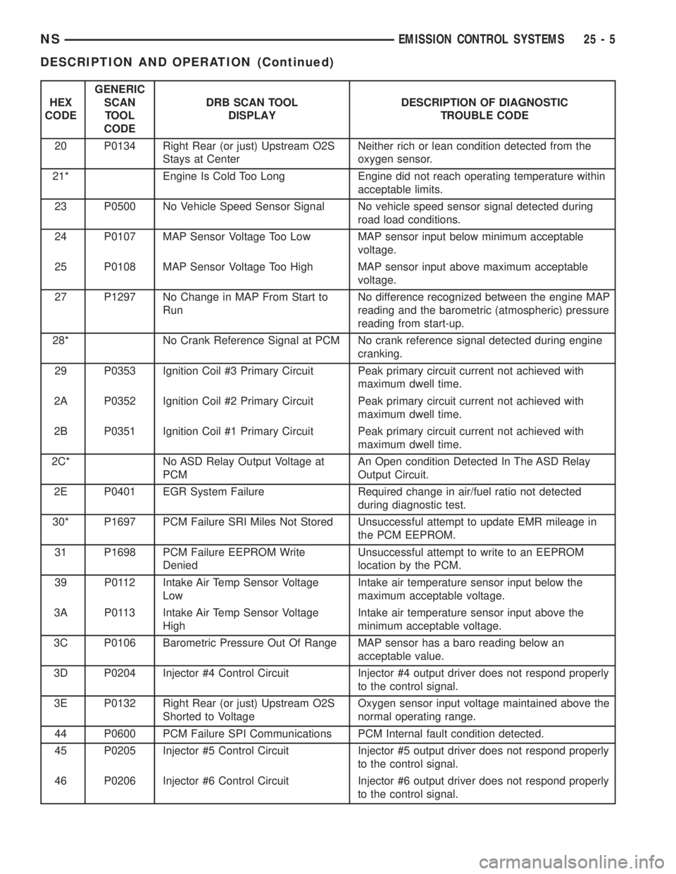
HEX
CODEGENERIC
SCAN
TOOL
CODEDRB SCAN TOOL
DISPLAYDESCRIPTION OF DIAGNOSTIC
TROUBLE CODE
20 P0134 Right Rear (or just) Upstream O2S
Stays at CenterNeither rich or lean condition detected from the
oxygen sensor.
21* Engine Is Cold Too Long Engine did not reach operating temperature within
acceptable limits.
23 P0500 No Vehicle Speed Sensor Signal No vehicle speed sensor signal detected during
road load conditions.
24 P0107 MAP Sensor Voltage Too Low MAP sensor input below minimum acceptable
voltage.
25 P0108 MAP Sensor Voltage Too High MAP sensor input above maximum acceptable
voltage.
27 P1297 No Change in MAP From Start to
RunNo difference recognized between the engine MAP
reading and the barometric (atmospheric) pressure
reading from start-up.
28* No Crank Reference Signal at PCM No crank reference signal detected during engine
cranking.
29 P0353 Ignition Coil #3 Primary Circuit Peak primary circuit current not achieved with
maximum dwell time.
2A P0352 Ignition Coil #2 Primary Circuit Peak primary circuit current not achieved with
maximum dwell time.
2B P0351 Ignition Coil #1 Primary Circuit Peak primary circuit current not achieved with
maximum dwell time.
2C* No ASD Relay Output Voltage at
PCMAn Open condition Detected In The ASD Relay
Output Circuit.
2E P0401 EGR System Failure Required change in air/fuel ratio not detected
during diagnostic test.
30* P1697 PCM Failure SRI Miles Not Stored Unsuccessful attempt to update EMR mileage in
the PCM EEPROM.
31 P1698 PCM Failure EEPROM Write
DeniedUnsuccessful attempt to write to an EEPROM
location by the PCM.
39 P0112 Intake Air Temp Sensor Voltage
LowIntake air temperature sensor input below the
maximum acceptable voltage.
3A P0113 Intake Air Temp Sensor Voltage
HighIntake air temperature sensor input above the
minimum acceptable voltage.
3C P0106 Barometric Pressure Out Of Range MAP sensor has a baro reading below an
acceptable value.
3D P0204 Injector #4 Control Circuit Injector #4 output driver does not respond properly
to the control signal.
3E P0132 Right Rear (or just) Upstream O2S
Shorted to VoltageOxygen sensor input voltage maintained above the
normal operating range.
44 P0600 PCM Failure SPI Communications PCM Internal fault condition detected.
45 P0205 Injector #5 Control Circuit Injector #5 output driver does not respond properly
to the control signal.
46 P0206 Injector #6 Control Circuit Injector #6 output driver does not respond properly
to the control signal.
NSEMISSION CONTROL SYSTEMS 25 - 5
DESCRIPTION AND OPERATION (Continued)
Page 1915 of 1938
components now have input (rationality) and output
(functionality) checks. Previously, a component like
the Throttle Position sensor (TPS) was checked by
the PCM for an open or shorted circuit. If one of
these conditions occurred, a DTC was set. Now there
is a check to ensure that the component is working.
This is done by watching for a TPS indication of a
greater or lesser throttle opening than MAP and
engine rpm indicate. In the case of the TPS, if engine
vacuum is high and engine rpm is 1600 or greater
and the TPS indicates a large throttle opening, a
DTC will be set. The same applies to low vacuum
and 1600 rpm.
Any component that has an associated limp in will
set a fault after 1 trip with the malfunction present.
Refer to the Diagnostic Trouble Codes Description
Charts in this section and the appropriate Power-
train Diagnostic Procedure Manual for diagnostic
procedures.
NON-MONITORED CIRCUITS
The PCM does not monitor all circuits, systems
and conditions that could have malfunctions causing
driveability problems. However, problems with these
systems may cause the PCM to store diagnostic trou-
ble codes for other systems or components. For exam-
ple, a fuel pressure problem will not register a fault
directly, but could cause a rich/lean condition or mis-
fire. This could cause the PCM to store an oxygen
sensor or misfire diagnostic trouble code.
The major non-monitored circuits are listed below
along with examples of failures modes that do not
directly cause the PCM to set a DTC, but for a sys-
tem that is monitored.
FUEL PRESSURE
The fuel pressure regulator controls fuel system
pressure. The PCM cannot detect a clogged fuel
pump inlet filter, clogged in-line fuel filter, or a
pinched fuel supply or return line. However, these
could result in a rich or lean condition causing the
PCM to store an oxygen sensor or fuel system diag-
nostic trouble code.
SECONDARY IGNITION CIRCUIT
The PCM cannot detect an inoperative ignition coil,
fouled or worn spark plugs, ignition cross firing, or
open spark plug cables.
CYLINDER COMPRESSION
The PCM cannot detect uneven, low, or high engine
cylinder compression.
EXHAUST SYSTEM
The PCM cannot detect a plugged, restricted or
leaking exhaust system. It may set a EGR or Fuel
system fault or O2S.
FUEL INJECTOR MECHANICAL
MALFUNCTIONS
The PCM cannot determine if a fuel injector is
clogged, the needle is sticking or if the wrong injector
is installed. However, these could result in a rich or
lean condition causing the PCM to store a diagnostic
trouble code for either misfire, an oxygen sensor, or
the fuel system.
EXCESSIVE OIL CONSUMPTION
Although the PCM monitors engine exhaust oxygen
content when the system is in closed loop, it cannot
determine excessive oil consumption.
THROTTLE BODY AIR FLOW
The PCM cannot detect a clogged or restricted air
cleaner inlet or filter element.
VACUUM ASSIST
The PCM cannot detect leaks or restrictions in the
vacuum circuits of vacuum assisted engine control
system devices. However, these could cause the PCM
to store a MAP sensor diagnostic trouble code and
cause a high idle condition.
PCM SYSTEM GROUND
The PCM cannot determine a poor system ground.
However, one or more diagnostic trouble codes may
be generated as a result of this condition. The mod-
ule should be mounted to the body at all times, also
during diagnostic.
PCM CONNECTOR ENGAGEMENT
The PCM may not be able to determine spread or
damaged connector pins. However, it might store
diagnostic trouble codes as a result of spread connec-
tor pins.
HIGH AND LOW LIMITS
The PCM compares input signal voltages from each
input device with established high and low limits for
the device. If the input voltage is not within limits
and other criteria are met, the PCM stores a diagnos-
tic trouble code in memory. Other diagnostic trouble
code criteria might include engine RPM limits or
input voltages from other sensors or switches that
must be present before verifying a diagnostic trouble
code condition.
NSEMISSION CONTROL SYSTEMS 25 - 11
DESCRIPTION AND OPERATION (Continued)