1996 CHRYSLER VOYAGER fuel cap
[x] Cancel search: fuel capPage 1380 of 1938
FUEL HEATER RELAY TEST
The fuel heater relay is located in the Power Dis-
tribution Center (PDC). Refer to RelaysÐOperation/
Testing in Fuel Ingection System section of this
group for test procedures.
FUEL INJECTOR TEST
The fuel injection nozzels, located on the engine
cylinder head, spray fuel under high pressure into
the individual combustion chambers. Pressurized
fuel, delivered by the fuel injection pump, unseats a
spring-loaded needle valve inside the injector, and
the fuel is atomized as it escapes through the injector
opening into the engine's combustion chamber. If the
fuel injector does not operate properly, the engine
may misfire, or cause other driveability problems.
A leak in the injection pump±to±injector high±pres-
sure fuel line can cause many of the same symptoms
as a malfunctioning injector. Inspect for a leak in the
high±pressure lines before checking for a malfunc-
tioning fuel injector.
WARNING: THE INJECTION PUMP SUPPLIES HIGH-
±PRESSURE FUEL OF UP TO APPROXIMATELY
45,000 KPA (6526 PSI) TO EACH INDIVIDUAL INJEC-
TOR THROUGH THE HIGH±PRESSURE LINES. FUEL
UNDER THIS AMOUNT OF PRESSURE CAN PENE-
TRATE THE SKIN AND CAUSE PERSONAL INJURY.
WEAR SAFETY GOGGLES AND ADEQUATE PRO-
TECTIVE CLOTHING. AVOID CONTACT WITH FUEL
SPRAY WHEN BLEEDING HIGH±PRESSURE FUEL
LINES.
WARNING: DO NOT BLEED AIR FROM THE FUEL
SYSTEM OF A HOT ENGINE. DO NOT ALLOW FUEL
TO SPRAY ONTO THE EXHAUST MANIFOLD WHEN
BLEEDING AIR FROM THE FUEL SYSTEM.
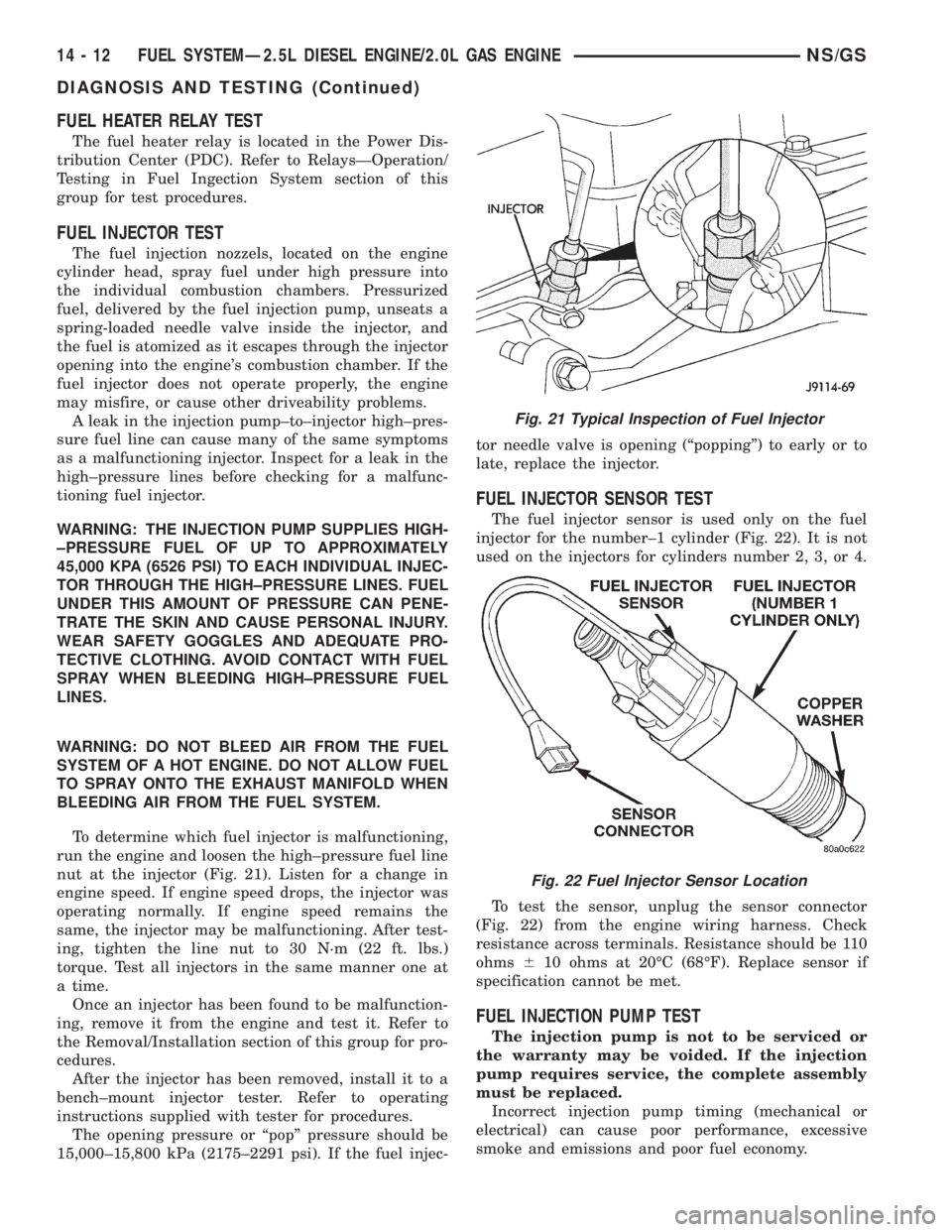
To determine which fuel injector is malfunctioning,
run the engine and loosen the high±pressure fuel line
nut at the injector (Fig. 21). Listen for a change in
engine speed. If engine speed drops, the injector was
operating normally. If engine speed remains the
same, the injector may be malfunctioning. After test-
ing, tighten the line nut to 30 N´m (22 ft. lbs.)
torque. Test all injectors in the same manner one at
a time.
Once an injector has been found to be malfunction-
ing, remove it from the engine and test it. Refer to
the Removal/Installation section of this group for pro-
cedures.
After the injector has been removed, install it to a
bench±mount injector tester. Refer to operating
instructions supplied with tester for procedures.
The opening pressure or ªpopº pressure should be
15,000±15,800 kPa (2175±2291 psi). If the fuel injec-tor needle valve is opening (ªpoppingº) to early or to
late, replace the injector.
FUEL INJECTOR SENSOR TEST
The fuel injector sensor is used only on the fuel
injector for the number±1 cylinder (Fig. 22). It is not
used on the injectors for cylinders number 2, 3, or 4.
To test the sensor, unplug the sensor connector
(Fig. 22) from the engine wiring harness. Check
resistance across terminals. Resistance should be 110
ohms610 ohms at 20ÉC (68ÉF). Replace sensor if
specification cannot be met.
FUEL INJECTION PUMP TEST
The injection pump is not to be serviced or
the warranty may be voided. If the injection
pump requires service, the complete assembly
must be replaced.
Incorrect injection pump timing (mechanical or
electrical) can cause poor performance, excessive
smoke and emissions and poor fuel economy.
Fig. 21 Typical Inspection of Fuel Injector
Fig. 22 Fuel Injector Sensor Location
14 - 12 FUEL SYSTEMÐ2.5L DIESEL ENGINE/2.0L GAS ENGINENS/GS
DIAGNOSIS AND TESTING (Continued)
Page 1393 of 1938
fuel fitting. Refer to Tube/Fitting Assembly in the
Fuel Delivery section of this Group.
(7) Attach filler line to filler tube. Pull on connec-
tor to make sure of connection.
(8) Fill fuel tank, replace cap, and connect battery
negative cable.
FUEL RESERVOIR MODULE
REMOVAL
WARNING: THE FUEL RESERVOIR OF THE FUEL
MODULE DOES NOT EMPTY OUT WHEN THE TANK
IS DRAINED. THE FUEL IN THE RESERVOIR WILL
SPILL OUT WHEN THE MODULE IS REMOVED.
(1) Disconnect negative cable from battery.
(2) Insert fuel siphon hose into fuel filler neck and
push it into the tank.
(3) Drain fuel tank dry into holding tank or a
properly labeleddieselsafety container.
(4) Raise vehicle on hoist.
(5) Use a transmission jack to support the fuel
tank. Remove bolts from fuel tank straps. Lower
tank slightly.
(6) Clean area around fuel reservoir module and
tank to keep dirt and foreign material out of tank.
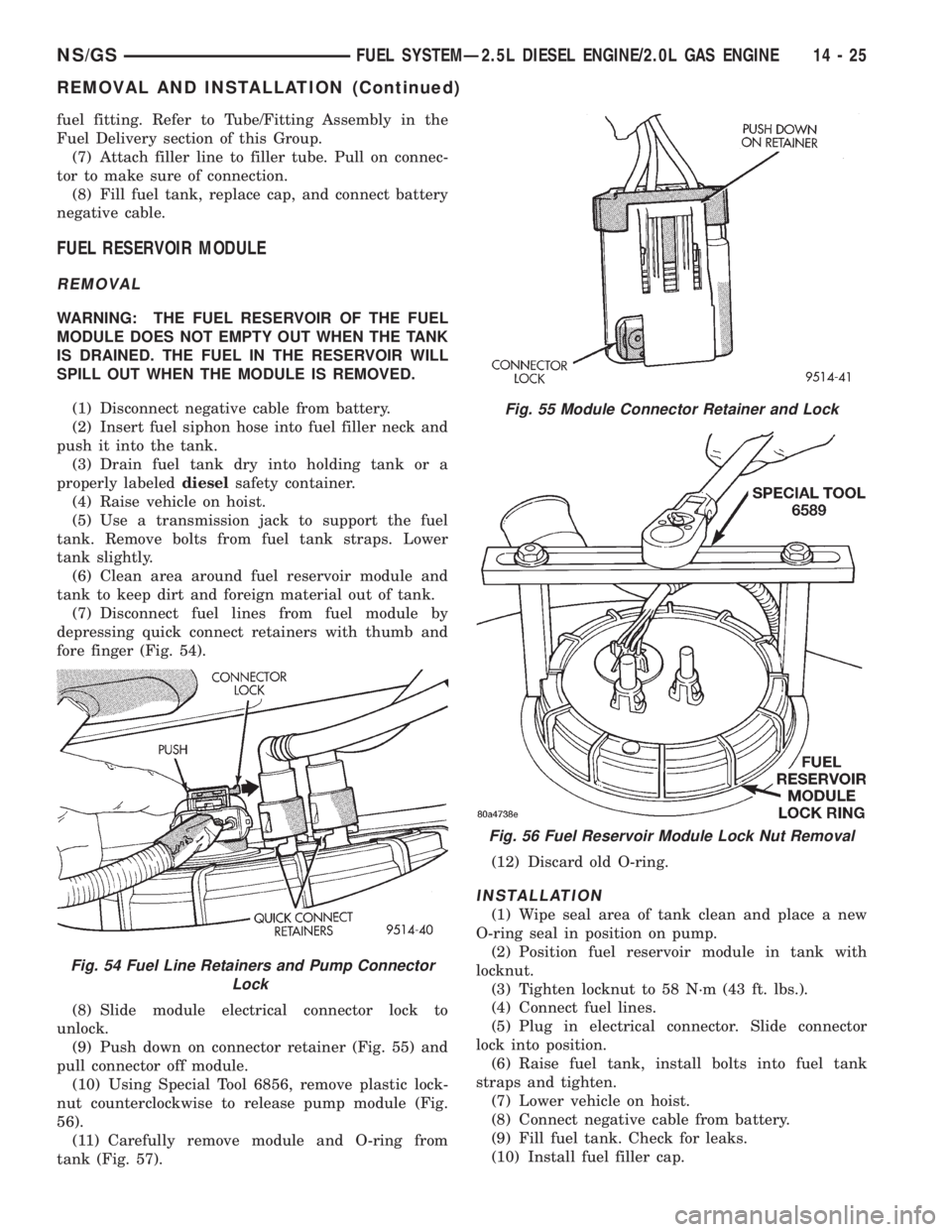
(7) Disconnect fuel lines from fuel module by
depressing quick connect retainers with thumb and
fore finger (Fig. 54).
(8) Slide module electrical connector lock to
unlock.
(9) Push down on connector retainer (Fig. 55) and
pull connector off module.
(10) Using Special Tool 6856, remove plastic lock-
nut counterclockwise to release pump module (Fig.
56).
(11) Carefully remove module and O-ring from
tank (Fig. 57).(12) Discard old O-ring.
INSTALLATION
(1) Wipe seal area of tank clean and place a new
O-ring seal in position on pump.
(2) Position fuel reservoir module in tank with
locknut.
(3) Tighten locknut to 58 N´m (43 ft. lbs.).
(4) Connect fuel lines.
(5) Plug in electrical connector. Slide connector
lock into position.
(6) Raise fuel tank, install bolts into fuel tank
straps and tighten.
(7) Lower vehicle on hoist.
(8) Connect negative cable from battery.
(9) Fill fuel tank. Check for leaks.
(10) Install fuel filler cap.
Fig. 54 Fuel Line Retainers and Pump Connector
Lock
Fig. 55 Module Connector Retainer and Lock
Fig. 56 Fuel Reservoir Module Lock Nut Removal
NS/GSFUEL SYSTEMÐ2.5L DIESEL ENGINE/2.0L GAS ENGINE 14 - 25
REMOVAL AND INSTALLATION (Continued)
Page 1395 of 1938
Be sure the lines are not contacting each
other or any other component.
(5) Tighten the clamp bracket bolts to 24 N´m (18
ft. lbs.) torque.
(6) Bleed air from the fuel system. Refer to the Air
Bleed Procedure section of this group.
SPECIFICATIONS
FUEL TANK CAPACITY
75 Liters (20.0 Gals.)
Nominal refill capacities are shown. A variation
may be observed from vehicle to vehicle due to man-
ufacturing tolerances, ambient temperatures and
refill procedures.
IDLE SPEED
900 rpm625 rpmwith engine at normal operat-
ing temperature.
FUEL INJECTOR FIRING SEQUENCE
1±3±4±2
FUEL SYSTEM PRESSURE
Peak Injection Pressure/Fuel Injection Pump
Operating Pressure:40,000±45,000 kPa (5801±
6526 psi).
Opening Pressure of Fuel Injector:
15,000±15,800 kPa (2175±2291 psi).
NS/GSFUEL SYSTEMÐ2.5L DIESEL ENGINE/2.0L GAS ENGINE 14 - 27
REMOVAL AND INSTALLATION (Continued)
Page 1396 of 1938
FUEL DELIVERY SYSTEMÐ2.0L ENGINE
INDEX
page page
DESCRIPTION AND OPERATION
ELECTRIC FUEL PUMP.................. 28
FUEL DELIVERY SYSTEM................ 28
FUEL INJECTORS...................... 28
FUEL LEVEL SENSOR................... 28
FUEL PRESSURE REGULATOR........... 28
FUEL PUMP MODULE................... 28
FUEL TANK........................... 28
PRESSURE-VACUUM FILLER CAPÐ
2.0L ENGINE......................... 28
QUICK-CONNNECT FITTINGSÐ
2.0L ENGINE......................... 28
DIAGNOSIS AND TESTING
FUEL INJECTORSÐ2.0L ENGINE.......... 29
FUEL LEVEL SENSORÐ2.0L ENGINE....... 28
FUEL PUMP PRESSURE TESTÐ
2.0L ENGINE......................... 28SERVICE PROCEDURES
FUEL SYSTEM PRESSURE RELEASE
PROCEDUREÐ2.0L ENGINE............ 29
HOSES AND CLAMPSÐ2.0L ENGINE....... 29
QUICK-CONNNECT FITTINGSÐ2.0L ENGINE . 29
REMOVAL AND INSTALLATION
ACCELERATOR PEDAL.................. 31
FUEL FILTERÐ2.0L ENGINE.............. 29
FUEL INJECTORS...................... 30
FUEL LEVEL SENSORÐ2.0L ENGINE....... 30
FUEL PRESSURE REGULATORÐ
2.0L ENGINE......................... 29
FUEL PRESSURE REGULATORÐ
2.0L ENGINE......................... 29
FUEL PUMP MODULEÐ2.0L ENGINE....... 29
FUEL TANKÐ2.0L ENGINE............... 30
TORQUE SPECIFICATION................ 31
DESCRIPTION AND OPERATION
FUEL DELIVERY SYSTEM
Refer to the Fuel Delivery Sytem in the Fuel Deliv-
ery Section of group 14 for the 2.4/3.0/3.3/3.8L
engines for more information.
FUEL PUMP MODULE
Refer to the Fuel Pump Module for the 2.4/3.0/3.3/
3.8L engines in the Fuel Delivery System section of
group 14.
ELECTRIC FUEL PUMP
Refer to the Electric Fuel Pump for the 2.4/3.0/3.3/
3.8L engines in the Fuel Delivery System Section of
group 14 for more information.
FUEL LEVEL SENSOR
Refer to the Fuel Level Sensor for the 2.4/3.0/3.3/
3.8L engines in the Fuel Delivery System section of
group 14 for more information.
FUEL PRESSURE REGULATOR
Refer to the Fuel Pressure Regulator for the 2.4/
3.0/3.3/3.8L engines in the Fuel Delivery System sec-
tion of group 14 for more information.
FUEL INJECTORS
Refer to the Fuel Injectors for the 2.4/3.0/3.3/3.8L
engines in the Fuel Delivery System section of group
14 for more information.
FUEL TANK
Refer to the Fuel Tank for the 2.4/3.0/3.3/3.8L
engines in the Fuel Delivery System section of group
14 for more information.
PRESSURE-VACUUM FILLER CAPÐ2.0L ENGINE
Refer to the Pressure-Vacuum Filler Cap for the
2.4/3.0/3.3/3.8L engines in the Fuel Delivery System
section of group 14 for more information.
QUICK-CONNNECT FITTINGSÐ2.0L ENGINE
Refer to the Quick Connect Fittings for the 2.4/3.0/
3.3/3.8L engines in the Fuel Delivery System section
of group 14 for more information.
DIAGNOSIS AND TESTING
FUEL PUMP PRESSURE TESTÐ2.0L ENGINE
Refer to the Fuel Pressure Test for the 2.4/3.0/3.3/
3.8L engines in the Fuel Delivery System section of
group 14 for more information.
FUEL LEVEL SENSORÐ2.0L ENGINE
Refer to the Fuel Level Sensor for the 2.4/3.0/3.3/
3.8L engines in the Fuel Delivery System section of
group 14 for more information.
14 - 28 FUEL SYSTEMÐ2.5L DIESEL ENGINE/2.0L GAS ENGINENS/GS
Page 1409 of 1938
Connect the DVM between the center and sensor
ground terminal. Refer to Group 8W - Wiring Dia-
grams for correct pinout.
With the ignition switch in the ON position, check
the output voltage at the center terminal wire of the
connector. Check the output voltage at idle and at
Wide-Open-Throttle (WOT). At idle, TPS output volt-
age should be approximately 0.38 volts to 1.2 volts.
At wide open throttle, TPS output voltage should be
approximately 3.1 volts to 4.4 volts. The output volt-
age should gradually increase as the throttle plate
moves slowly from idle to WOT.
Check for spread terminals at the sensor and PCM
connections before replacing the TPS.
THROTTLE BODY MINIMUM AIR FLOW
(1) Turn ignition key to Off.
(2) D
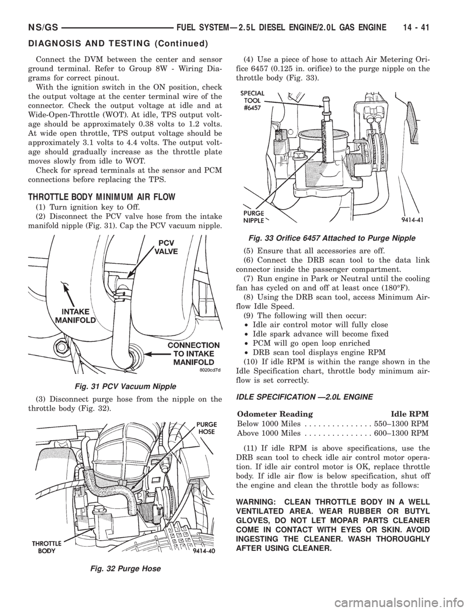
isconnect the PCV valve hose from the intake
manifold nipple (Fig. 31). Cap the PCV vacuum nipple.
(3) Disconnect purge hose from the nipple on the
throttle body (Fig. 32).(4) Use a piece of hose to attach Air Metering Ori-
fice 6457 (0.125 in. orifice) to the purge nipple on the
throttle body (Fig. 33).
(5) Ensure that all accessories are off.
(6) Connect the DRB scan tool to the data link
connector inside the passenger compartment.
(7) Run engine in Park or Neutral until the cooling
fan has cycled on and off at least once (180ÉF).
(8) Using the DRB scan tool, access Minimum Air-
flow Idle Speed.
(9) The following will then occur:
²Idle air control motor will fully close
²Idle spark advance will become fixed
²PCM will go open loop enriched
²DRB scan tool displays engine RPM
(10) If idle RPM is within the range shown in the
Idle Specification chart, throttle body minimum air-
flow is set correctly.IDLE SPECIFICATION Ð2.0L ENGINE
Odometer Reading Idle RPM
Below 1000 Miles...............550±1300 RPM
Above 1000 Miles...............600±1300 RPM
(11) If idle RPM is above specifications, use the
DRB scan tool to check idle air control motor opera-
tion. If idle air control motor is OK, replace throttle
body. If idle air flow is below specification, shut off
the engine and clean the throttle body as follows:
WARNING: CLEAN THROTTLE BODY IN A WELL
VENTILATED AREA. WEAR RUBBER OR BUTYL
GLOVES, DO NOT LET MOPAR PARTS CLEANER
COME IN CONTACT WITH EYES OR SKIN. AVOID
INGESTING THE CLEANER. WASH THOROUGHLY
AFTER USING CLEANER.
Fig. 31 PCV Vacuum Nipple
Fig. 32 Purge Hose
Fig. 33 Orifice 6457 Attached to Purge Nipple
NS/GSFUEL SYSTEMÐ2.5L DIESEL ENGINE/2.0L GAS ENGINE 14 - 41
DIAGNOSIS AND TESTING (Continued)
Page 1410 of 1938
(a) Remove the throttle body from engine.
(b) While holding the throttle open, spray the
entire throttle body bore and the manifold side of
the throttle plate with Mopar Parts Cleaner.Only
use Mopar Parts Cleaner to clean the throttle
body.
(c) Using a soft scuff pad, clean the top and bot-
tom of throttle body bore and the edges and mani-
fold side of the throttle blade.The edges of the
throttle blade and portions of the throttle
bore that are closest to the throttle blade
when closed, must be free of deposits.
(d) Use compressed air to dry the throttle body.
(e) Inspect throttle body for foreign material.
(f) Install throttle body on manifold.
(g) Repeat steps 1 through 14. If the minimum
air flow is still not within specifications, the prob-
lem is not caused by the throttle body.
(12) Shut off engine.
(13) Remove Air Metering Orifice 6457. Install
purge hose.
(14) Remove cap from PCV valve. Connect hose to
PCV valve.
(15) Remove DRB scan tool.SPECIFICATIONS
TORQUE
DESCRIPTION TORQUE
Air Cleaner Wingnut.........1.5N´m(15in.lbs.)
Air Cleaner Mount. Stud-To-Thrott. Body . . 10 N´m
(90 in. lbs.)
Crankshaft Position Sensor Mounting Bolts . . 8 N´m
(70 in. lbs.)
Engine Coolant Temperature Sensor......18N´m
(165 in. lbs.)
IAC Motor-To-Throttle Body Bolts.........7N´m
(60 in. lbs.)
MAP/IAT Sensor.............2N´m(20in.lbs.)
MAP/IAT Sensor.............3N´m(30in.lbs.)
Oxygen Sensor..............28N´m(20ft.lbs.)
Powertrain Control Module
(PCM) Mounting Screws.....4N´m(35in.lbs.)
Throttle Cable Cover........4.5N´m(40in.lbs.).
Throttle Body Mounting Bolts...........23N´m
(200 in. lbs.)
Throttle Position Sensor Mounting Screws . . . 2 N´m
(20 in. lbs.)
Vehicle Speed Sensor Mounting Bolt......2.2N´m
(20 in. lbs.)
14 - 42 FUEL SYSTEMÐ2.5L DIESEL ENGINE/2.0L GAS ENGINENS/GS
DIAGNOSIS AND TESTING (Continued)
Page 1721 of 1938
Improper inflation can cause:
²Uneven wear patterns
²Reduced tread life
²Reduced fuel economy
²Unsatisfactory ride
²The vehicle to drift.
Proper tire air inflation pressure specifications can
be found on the Vehicle Tire Placard provided with
the vehicle. See owner's manual.
Tire pressures have been chosen to provide safe
operation, vehicle stability, and a smooth ride. Tire
pressure should be checked cold once per month.
Check tire pressure more frequently when the
weather temperature varies widely. Tire pressure will
decrease when the outdoor temperature drops.
Tire inflation pressures specified on the placard
are always cold inflation pressure. Cold inflation
pressure is obtained after the vehicle has not been
operated for at least 3 hours, or the vehicle is driven
less than one mile after being inoperative for 3
hours. Tire inflation pressures may increase from 2
to 6 pounds per square inch (psi) during operation.
Do not reduce this normal pressure build-up.
TIRE PRESSURE FOR HIGH-SPEED DRIVING
Chrysler Corporation advocates driving at safe
speeds within posted speed limits. Where speed lim-
its allow the vehicle to be driven at high speeds, cor-
rect tire inflation pressure is very important. For
speeds up to and including 75 mph (120 km/h), tires
must be inflated to the pressures shown on the tire
placard.
Vehicles loaded to the maximum capacity should
not be driven at speeds above 75 mph (120 km/h).
For emergency vehicles that are driven at speeds
over 90 mph (144 km/h), special high-speed tires
must be used. Consult tire manufacturer for correct
inflation pressure recommendations.
REPLACEMENT TIRES
The original equipment tires provide a proper bal-
ance of many characteristics such as:
²Ride
²Noise
²Handling
²Durability
²Tread life
²Traction
²Rolling resistance
²Speed capability
It is recommend that tires equivalent to the origi-
nal equipment tires be used when replacement is
needed.
Failure to use equivalent replacement tires may
adversely affect the safety and handling of the vehicle.
The use of oversize tires not listed in the specifica-
tion charts may cause interference with vehicle com-
ponents. Under extremes of suspension and steering
travel, interference with vehicle components may
cause tire damage.
WARNING: FAILURE TO EQUIP THE VEHICLE WITH
TIRES HAVING ADEQUATE SPEED CAPABILITY
CAN RESULT IN SUDDEN TIRE FAILURE.
DIAGNOSIS AND TESTING
PRESSURE GAUGES
A quality air pressure gauge is recommended to
check tire pressure. After checking the air pressure,
replace valve cap finger tight.
TREAD WEAR INDICATORS
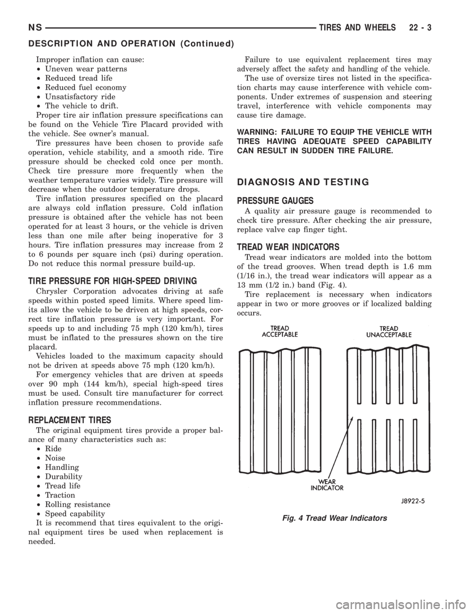
Tread wear indicators are molded into the bottom
of the tread grooves. When tread depth is 1.6 mm
(1/16 in.), the tread wear indicators will appear as a
13 mm (1/2 in.) band (Fig. 4).
Tire replacement is necessary when indicators
appear in two or more grooves or if localized balding
occurs.
Fig. 4 Tread Wear Indicators
NSTIRES AND WHEELS 22 - 3
DESCRIPTION AND OPERATION (Continued)
Page 1913 of 1938
conditions are met, the EGR is turned off (solenoid
energized) and the O2S compensation control is mon-
itored. Turning off the EGR shifts the air fuel (A/F)
ratio in the lean direction. The O2S data should indi-
cate an increase in the O2 concentration in the com-
bustion chamber when the exhaust gases are no
longer recirculated. While this test does not directly
measure the operation of the EGR system, it can be
inferred from the shift in the O2S data whether the
EGR system is operating correctly. Because the O2S
is being used, the O2S test must pass its test before
the EGR test.
HEX 6A,6B, 6C, 6D, 6E, AE, and AFÐMISFIRE
MONITOR
Excessive engine misfire results in increased cata-
lyst temperature and causes an increase in HC emis-
sions. Severe misfires could cause catalyst damage.
To prevent catalytic convertor damage, the PCM
monitors engine misfire.
The Powertrain Control Module (PCM) monitors
for misfire during most engine operating conditions
(positive torque) by looking at changes in the crank-
shaft speed. If a misfire occurs the speed of the
crankshaft will vary more than normal.
HEX 76, 77, 78, and 79ÐFUEL SYSTEM
MONITOR
To comply with clean air regulations, vehicles are
equipped with catalytic converters. These converters
reduce the emission of hydrocarbons, oxides of nitro-
gen and carbon monoxide. The catalyst works best
when the air fuel (A/F) ratio is at or near the opti-
mum of 14.7 to 1.
The PCM is programmed to maintain the optimum
air/fuel ratio of 14.7 to 1. This is done by making
short term corrections in the fuel injector pulse width
based on the O2S output. The programmed memory
acts as a self calibration tool that the engine control-
ler uses to compensate for variations in engine spec-
ifications, sensor tolerances and engine fatigue over
the life span of the engine. By monitoring the actual
air-fuel ratio with the O2S (short term) and multiply-
ing that with the program long-term (adaptive) mem-
ory and comparing that to the limit, it can be
determined whether it will pass an emissions test. If
a malfunction occurs such that the PCM cannot
maintain the optimum A/F ratio, then the MIL will
be illuminated.
HEX 70, and B4ÐCATALYST MONITOR
To comply with clean air regulations, vehicles are
equipped with catalytic converters. These converters
reduce the emission of hydrocarbons, oxides of nitro-
gen and carbon monoxide.Normal vehicle miles or engine misfire can cause a
catalyst to decay. A meltdown of the ceramic core can
cause a reduction of the exhaust passage. This can
increase vehicle emissions and deteriorate engine
performance, driveability and fuel economy.
The catalyst monitor uses dual oxygen sensors
(O2S's) to monitor the efficiency of the converter. The
dual O2Ss strategy is based on the fact that as a cat-
alyst deteriorates, its oxygen storage capacity and its
efficiency are both reduced. By monitoring the oxy-
gen storage capacity of a catalyst, its efficiency can
be indirectly calculated. The upstream O2S is used to
detect the amount of oxygen in the exhaust gas
before the gas enters the catalytic converter. The
PCM calculates the A/F mixture from the output of
the O2S. A low voltage indicates high oxygen content
(lean mixture). A high voltage indicates a low content
of oxygen (rich mixture).
When the upstream O2S detects a lean condition,
there is an abundance of oxygen in the exhaust gas.
A functioning converter would store this oxygen so it
can use it for the oxidation of HC and CO. As the
converter absorbs the oxygen, there will be a lack of
oxygen downstream of the converter. The output of
the downstraem O2S will indicate limited activity in
this condition.
As the converter loses the ability to store oxygen,
the condition can be detected from the behavior of
the downstream O2S. When the efficiency drops, no
chemical reaction takes place. This means the con-
centration of oxygen will be the same downstream as
upstream. The output voltage of the downstream
O2S copies the voltage of the upstream sensor. The
only difference is a time lag (seen by the PCM)
between the switching of the O2S's.
To monitor the system, the number of lean-to-rich
switches of upstream and downstream O2S's is
counted. The ratio of downstream switches to
upstream switches is used to determine whether the
catalyst is operating properly. An effective catalyst
will have fewer downstream switches than it has
upstream switches i.e., a ratio closer to zero. For a
totally ineffective catalyst, this ratio will be one-to-
one, indicating that no oxidation occurs in the device.
The system must be monitored so that when cata-
lyst efficiency deteriorates and exhaust emissions
increase to over the legal limit, the MIL (check
engine lamp) will be illuminated.
HEX A0, A1, B7, and B8ÐLEAK DETECTION
PUMP MONITOR
The leak detection assembly incorporates two pri-
mary functions: it must detect a leak in the evapora-
tive system and seal the evaporative system so the
leak detection test can be run.
NSEMISSION CONTROL SYSTEMS 25 - 9
DESCRIPTION AND OPERATION (Continued)