1996 CHRYSLER VOYAGER fuel cap
[x] Cancel search: fuel capPage 1319 of 1938
INSTALLATION
(1) Before installing an injector the rubber O-ring
must be lubricated with a drop of clean engine oil to
aid in installation.
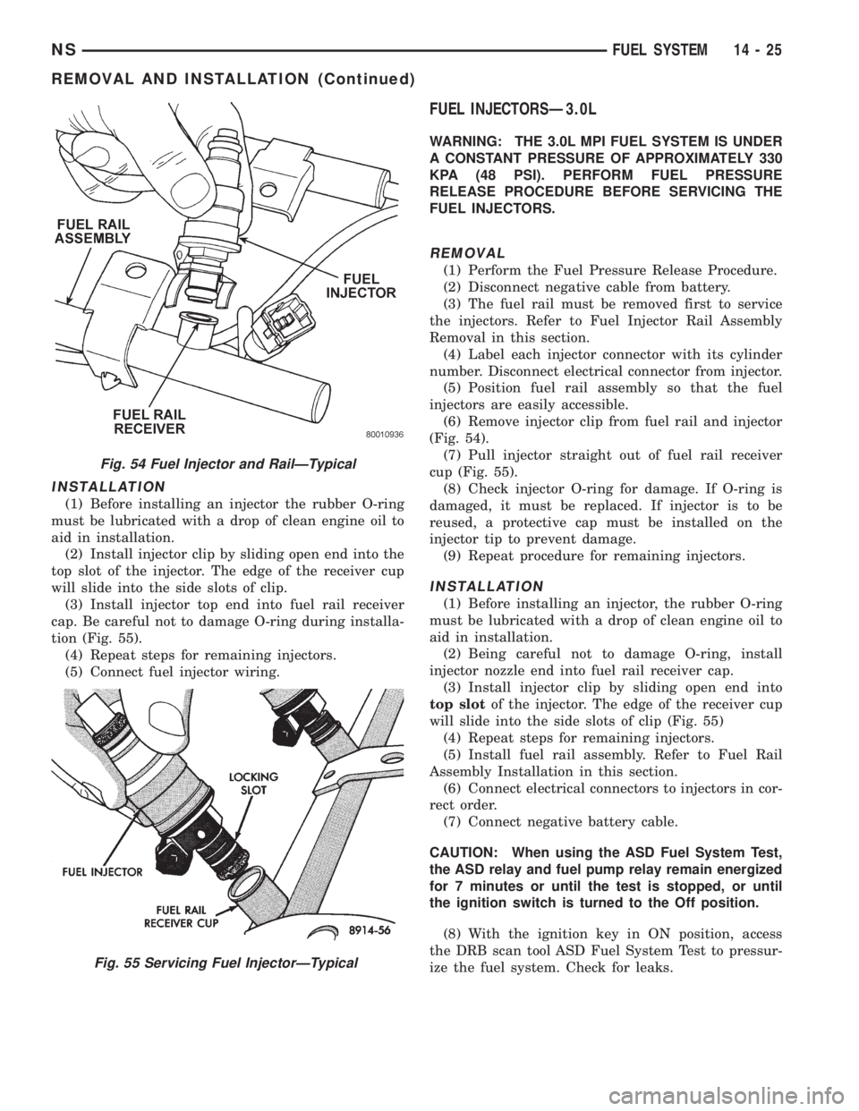
(2) Install injector clip by sliding open end into the
top slot of the injector. The edge of the receiver cup
will slide into the side slots of clip.
(3) Install injector top end into fuel rail receiver
cap. Be careful not to damage O-ring during installa-
tion (Fig. 55).
(4) Repeat steps for remaining injectors.
(5) Connect fuel injector wiring.
FUEL INJECTORSÐ3.0L
WARNING: THE 3.0L MPI FUEL SYSTEM IS UNDER
A CONSTANT PRESSURE OF APPROXIMATELY 330
KPA (48 PSI). PERFORM FUEL PRESSURE
RELEASE PROCEDURE BEFORE SERVICING THE
FUEL INJECTORS.
REMOVAL
(1) Perform the Fuel Pressure Release Procedure.
(2) Disconnect negative cable from battery.
(3) The fuel rail must be removed first to service
the injectors. Refer to Fuel Injector Rail Assembly
Removal in this section.
(4) Label each injector connector with its cylinder
number. Disconnect electrical connector from injector.
(5) Position fuel rail assembly so that the fuel
injectors are easily accessible.
(6) Remove injector clip from fuel rail and injector
(Fig. 54).
(7) Pull injector straight out of fuel rail receiver
cup (Fig. 55).
(8) Check injector O-ring for damage. If O-ring is
damaged, it must be replaced. If injector is to be
reused, a protective cap must be installed on the
injector tip to prevent damage.
(9) Repeat procedure for remaining injectors.
INSTALLATION
(1) Before installing an injector, the rubber O-ring
must be lubricated with a drop of clean engine oil to
aid in installation.
(2) Being careful not to damage O-ring, install
injector nozzle end into fuel rail receiver cap.
(3) Install injector clip by sliding open end into
top slotof the injector. The edge of the receiver cup
will slide into the side slots of clip (Fig. 55)
(4) Repeat steps for remaining injectors.
(5) Install fuel rail assembly. Refer to Fuel Rail
Assembly Installation in this section.
(6) Connect electrical connectors to injectors in cor-
rect order.
(7) Connect negative battery cable.
CAUTION: When using the ASD Fuel System Test,
the ASD relay and fuel pump relay remain energized
for 7 minutes or until the test is stopped, or until
the ignition switch is turned to the Off position.
(8) With the ignition key in ON position, access
the DRB scan tool ASD Fuel System Test to pressur-
ize the fuel system. Check for leaks.
Fig. 54 Fuel Injector and RailÐTypical
Fig. 55 Servicing Fuel InjectorÐTypical
NSFUEL SYSTEM 14 - 25
REMOVAL AND INSTALLATION (Continued)
Page 1320 of 1938
FUEL INJECTORÐ3.3/3.8L
The fuel rail must be removed first. Refer to Fuel
Injector Rail Assembly Removal in this section.
REMOVAL
(1) Disconnect injector wiring connector from injec-
tor.
(2) Position fuel rail assembly so that the fuel
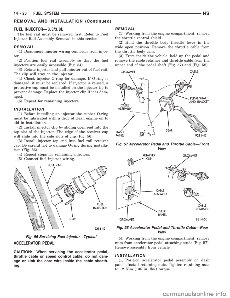
injectors are easily accessible (Fig. 54).
(3) Rotate injector and pull injector out of fuel rail.
The clip will stay on the injector.
(4) Check injector O-ring for damage. If O-ring is
damaged, it must be replaced. If injector is reused, a
protective cap must be installed on the injector tip to
prevent damage. Replace the injector clip if it is dam-
aged.
(5) Repeat for remaining injectors.
INSTALLATION
(1) Before installing an injector the rubber O-ring
must be lubricated with a drop of clean engine oil to
aid in installation.
(2) Install injector clip by sliding open end into the
top slot of the injector. The edge of the receiver cup
will slide into the side slots of clip (Fig. 56).
(3) Install injector top end into fuel rail receiver
cap. Be careful not to damage O-ring during installa-
tion (Fig. 56).
(4) Repeat steps for remaining injectors.
(5) Connect fuel injector wiring.
ACCELERATOR PEDAL
CAUTION: When servicing the accelerator pedal,
throttle cable or speed control cable, do not dam-
age or kink the core wire inside the cable sheath-
ing.
REMOVAL
(1) Working from the engine compartment, remove
the throttle control shield.
(2) Hold the throttle body throttle lever in the
wide open position. Remove the throttle cable from
the throttle body cam.
(3) From inside the vehicle, hold up the pedal and
remove the cable retainer and throttle cable from the
upper end of the pedal shaft (Fig. 57) and (Fig. 58).
(4) Working from the engine compartment, remove
nuts from accelerator pedal attaching studs (Fig. 57).
Remove assembly from vehicle.
INSTALLATION
(1) Position accelerator pedal assembly on dash
panel. Install retaining nuts. Tighten retaining nuts
to 12 N´m (105 in. lbs.) torque.
Fig. 56 Servicing Fuel InjectorÐTypical
Fig. 57 Accelerator Pedal and Throttle CableÐFront
View
Fig. 58 Accelerator Pedal and Throttle CableÐRear
View
14 - 26 FUEL SYSTEMNS
REMOVAL AND INSTALLATION (Continued)
Page 1322 of 1938
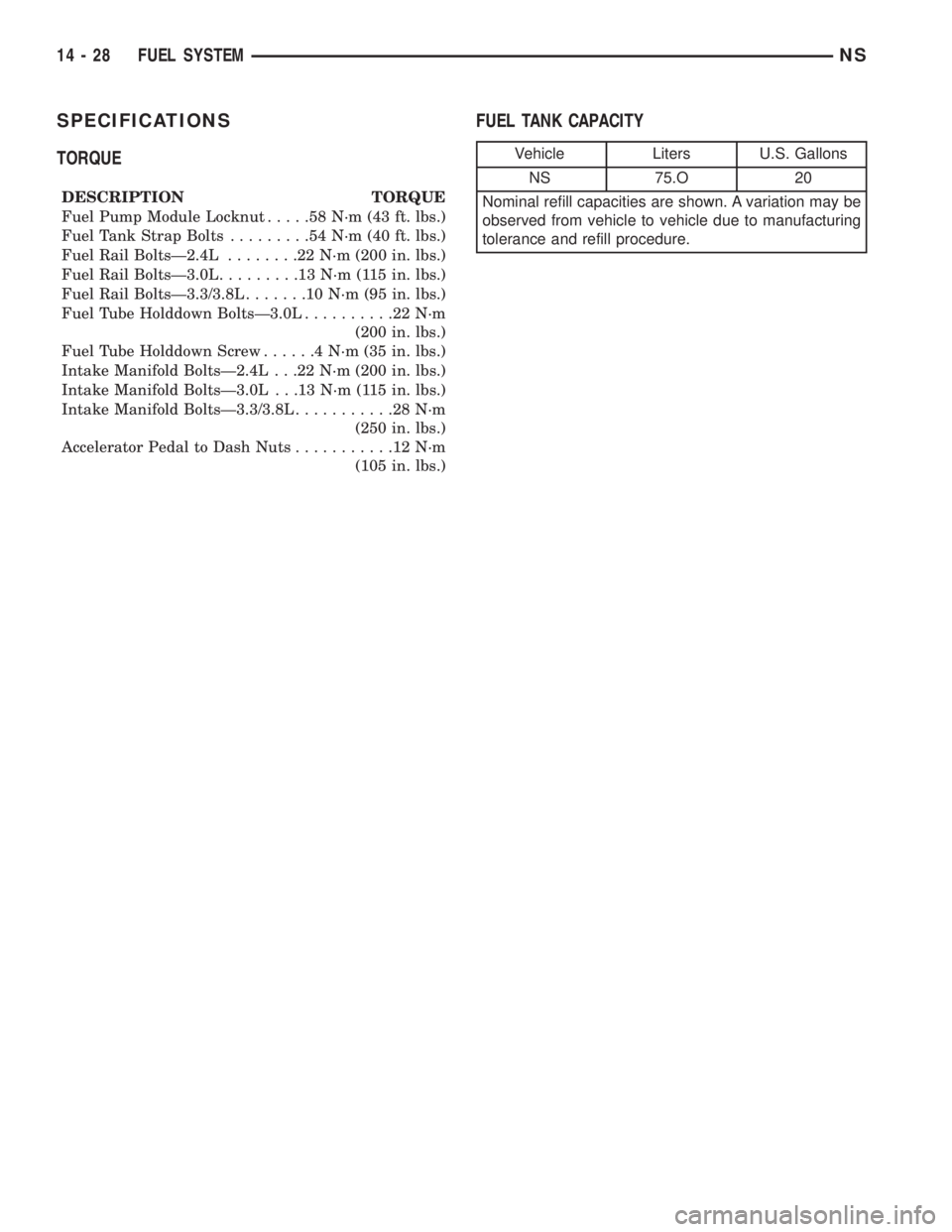
SPECIFICATIONS
TORQUE
DESCRIPTION TORQUE
Fuel Pump Module Locknut.....58N´m(43ft.lbs.)
Fuel Tank Strap Bolts.........54N´m(40ft.lbs.)
Fuel Rail BoltsÐ2.4L........22N´m(200 in. lbs.)
Fuel Rail BoltsÐ3.0L.........13N´m(115in.lbs.)
Fuel Rail BoltsÐ3.3/3.8L.......10N´m(95in.lbs.)
Fuel Tube Holddown BoltsÐ3.0L..........22N´m
(200 in. lbs.)
Fuel Tube Holddown Screw......4N´m(35in.lbs.)
Intake Manifold BoltsÐ2.4L . . .22 N´m (200 in. lbs.)
Intake Manifold BoltsÐ3.0L . . .13 N´m (115 in. lbs.)
Intake Manifold BoltsÐ3.3/3.8L...........28N´m
(250 in. lbs.)
Accelerator Pedal to Dash Nuts...........12N´m
(105 in. lbs.)
FUEL TANK CAPACITY
Vehicle Liters U.S. Gallons
NS 75.O 20
Nominal refill capacities are shown. A variation may be
observed from vehicle to vehicle due to manufacturing
tolerance and refill procedure.
14 - 28 FUEL SYSTEMNS
Page 1356 of 1938
circuit information. If the resistance is greater than 1
ohm, repair the wire harness as necessary.
THROTTLE POSITION SENSOR
To perform a complete test of the this sensor and
its circuitry, refer to the DRB scan tool and appropri-
ate Powertrain Diagnostics Procedures manual. To
test the throttle position sensor only, refer to the fol-
lowing:
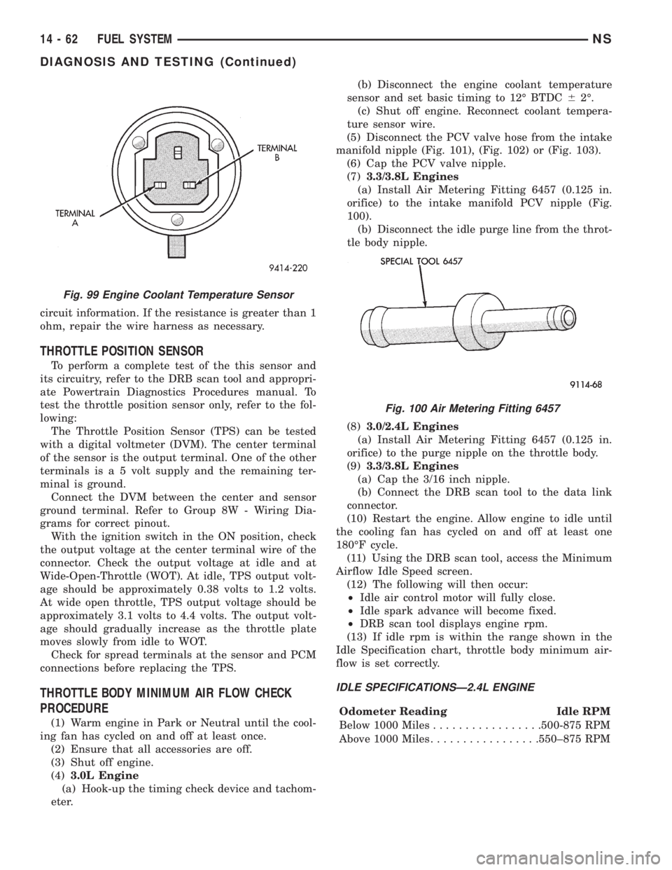
The Throttle Position Sensor (TPS) can be tested
with a digital voltmeter (DVM). The center terminal
of the sensor is the output terminal. One of the other
terminals is a 5 volt supply and the remaining ter-
minal is ground.
Connect the DVM between the center and sensor
ground terminal. Refer to Group 8W - Wiring Dia-
grams for correct pinout.
With the ignition switch in the ON position, check
the output voltage at the center terminal wire of the
connector. Check the output voltage at idle and at
Wide-Open-Throttle (WOT). At idle, TPS output volt-
age should be approximately 0.38 volts to 1.2 volts.
At wide open throttle, TPS output voltage should be
approximately 3.1 volts to 4.4 volts. The output volt-
age should gradually increase as the throttle plate
moves slowly from idle to WOT.
Check for spread terminals at the sensor and PCM
connections before replacing the TPS.
THROTTLE BODY MINIMUM AIR FLOW CHECK
PROCEDURE
(1) Warm engine in Park or Neutral until the cool-
ing fan has cycled on and off at least once.
(2) Ensure that all accessories are off.
(3) Shut off engine.
(4)3.0L Engine
(a) Hook-up the timing check device and tachom-
eter.(b) Disconnect the engine coolant temperature
sensor and set basic timing to 12É BTDC62É.
(c) Shut off engine. Reconnect coolant tempera-
ture sensor wire.
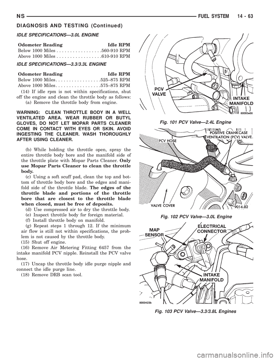
(5) Disconnect the PCV valve hose from the intake
manifold nipple (Fig. 101), (Fig. 102) or (Fig. 103).
(6) Cap the PCV valve nipple.
(7)3.3/3.8L Engines
(a) Install Air Metering Fitting 6457 (0.125 in.
orifice) to the intake manifold PCV nipple (Fig.
100).
(b) Disconnect the idle purge line from the throt-
tle body nipple.
(8)3.0/2.4L Engines
(a) Install Air Metering Fitting 6457 (0.125 in.
orifice) to the purge nipple on the throttle body.
(9)3.3/3.8L Engines
(a) Cap the 3/16 inch nipple.
(b) Connect the DRB scan tool to the data link
connector.
(10) Restart the engine. Allow engine to idle until
the cooling fan has cycled on and off at least one
180ÉF cycle.
(11) Using the DRB scan tool, access the Minimum
Airflow Idle Speed screen.
(12) The following will then occur:
²Idle air control motor will fully close.
²Idle spark advance will become fixed.
²DRB scan tool displays engine rpm.
(13) If idle rpm is within the range shown in the
Idle Specification chart, throttle body minimum air-
flow is set correctly.
IDLE SPECIFICATIONSÐ2.4L ENGINE
Odometer Reading Idle RPM
Below 1000 Miles.................500-875 RPM
Above 1000 Miles.................550±875 RPM
Fig. 99 Engine Coolant Temperature Sensor
Fig. 100 Air Metering Fitting 6457
14 - 62 FUEL SYSTEMNS
DIAGNOSIS AND TESTING (Continued)
Page 1357 of 1938
IDLE SPECIFICATIONSÐ3.0L ENGINE
Odometer Reading Idle RPM
Below 1000 Miles.................560-910 RPM
Above 1000 Miles.................610-910 RPM
IDLE SPECIFICATIONSÐ3.3/3.3L ENGINE
Odometer Reading Idle RPM
Below 1000 Miles.................525±875 RPM
Above 1000 Miles.................575±875 RPM
(14) If idle rpm is not within specifications, shut
off the engine and clean the throttle body as follows:
(a) Remove the throttle body from engine.
WARNING: CLEAN THROTTLE BODY IN A WELL
VENTILATED AREA. WEAR RUBBER OR BUTYL
GLOVES, DO NOT LET MOPAR PARTS CLEANER
COME IN CONTACT WITH EYES OR SKIN. AVOID
INGESTING THE CLEANER. WASH THOROUGHLY
AFTER USING CLEANER.
(b) While holding the throttle open, spray the
entire throttle body bore and the manifold side of
the throttle plate with Mopar Parts Cleaner.Only
use Mopar Parts Cleaner to clean the throttle
body.
(c) Using a soft scuff pad, clean the top and bot-
tom of throttle body bore and the edges and mani-
fold side of the throttle blade.The edges of the
throttle blade and portions of the throttle
bore that are closest to the throttle blade
when closed, must be free of deposits.
(d) Use compressed air to dry the throttle body.
(e) Inspect throttle body for foreign material.
(f) Install throttle body on manifold.
(g) Repeat steps 1 through 12. If the minimum
air flow is still not within specifications, the prob-
lem is not caused by the throttle body.
(15) Shut off engine.
(16) Remove Air Metering Fitting 6457 from the
intake manifold PCV nipple. Reinstall the PCV valve
hose.
(17) Uncap the throttle body idle purge nipple and
connect the idle purge line.
(18) Remove DRB scan tool.
Fig. 101 PCV ValveÐ2.4L Engine
Fig. 102 PCV ValveÐ3.0L Engine
Fig. 103 PCV ValveÐ3.3/3.8L Engines
NSFUEL SYSTEM 14 - 63
DIAGNOSIS AND TESTING (Continued)
Page 1369 of 1938
FUEL SYSTEMÐ2.5L DIESEL ENGINE/2.0L GAS ENGINE
CONTENTS
page page
FUEL DELIVERY SYSTEMÐ2.0L ENGINE.... 28
FUEL DELIVERY SYSTEMÐ2.5L DIESEL
ENGINE.............................. 3
FUEL INJECTION SYSTEMÐ2.0L ENGINE . . . 32FUEL INJECTION SYSTEMÐ2.5L DIESEL
ENGINE............................. 43
GENERAL INFORMATION.................. 1
GENERAL INFORMATION
INDEX
page page
GENERAL INFORMATION
FUEL REQUIREMENTSÐ2.0L ENGINE....... 2
FUEL REQUIREMENTSÐ2.5L DIESEL........ 2GASOLINE/OXYGENATE BLENDS........... 2
INTRODUCTIONÐ2.0L ENGINE............. 2
INTRODUCTIONÐ2.5L DIESEL............. 1
GENERAL INFORMATION
INTRODUCTIONÐ2.5L DIESEL
Certain components of the fuel system on the 2.5L
diesel engine are controlled by the Bosch Engine con-
troller which is a Powertrain Control Module (PCM).
Refer to Powertrain Control Module in the Fuel
Injection SystemÐ2.5L Diesel Engine section of this
group for a list of items controlled by the PCM. The
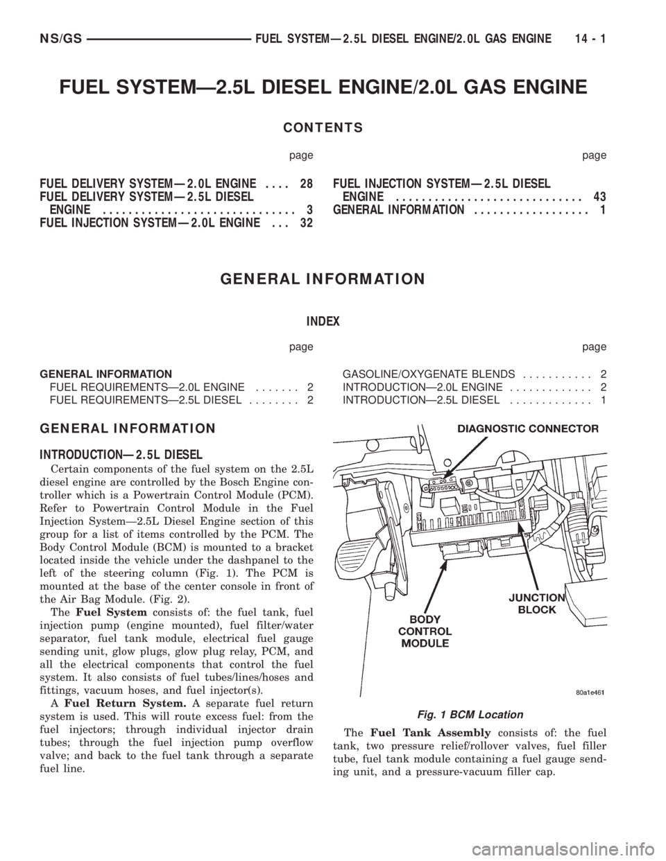
Body Control Module (BCM) is mounted to a bracket
located inside the vehicle under the dashpanel to the
left of the steering column (Fig. 1). The PCM is
mounted at the base of the center console in front of
the Air Bag Module. (Fig. 2).
TheFuel Systemconsists of: the fuel tank, fuel
injection pump (engine mounted), fuel filter/water
separator, fuel tank module, electrical fuel gauge
sending unit, glow plugs, glow plug relay, PCM, and
all the electrical components that control the fuel
system. It also consists of fuel tubes/lines/hoses and
fittings, vacuum hoses, and fuel injector(s).
AFuel Return System.A separate fuel return
system is used. This will route excess fuel: from the
fuel injectors; through individual injector drain
tubes; through the fuel injection pump overflow
valve; and back to the fuel tank through a separate
fuel line.TheFuel Tank Assemblyconsists of: the fuel
tank, two pressure relief/rollover valves, fuel filler
tube, fuel tank module containing a fuel gauge send-
ing unit, and a pressure-vacuum filler cap.
Fig. 1 BCM Location
NS/GSFUEL SYSTEMÐ2.5L DIESEL ENGINE/2.0L GAS ENGINE 14 - 1
Page 1371 of 1938
FUEL DELIVERY SYSTEMÐ2.5L DIESEL ENGINE
INDEX
page page
DESCRIPTION AND OPERATION
FUEL DRAIN TUBES..................... 7
FUEL FILTER/WATER SEPARATOR.......... 4
FUEL GAUGE SENDING UNIT.............. 4
FUEL HEATER RELAY.................... 8
FUEL HEATER.......................... 8
FUEL INJECTION PUMP.................. 5
FUEL INJECTORS....................... 6
FUEL SHUTDOWN SOLENOID............. 5
FUEL SYSTEM PRESSURE WARNING....... 3
FUEL TANK MODULE.................... 4
FUEL TANK............................ 3
FUEL TUBES/LINES/HOSES AND CLAMPSÐ
LOW-PRESSURE TYPE................. 6
HIGH-PRESSURE FUEL LINES............. 7
INTRODUCTION........................ 3
QUICK-CONNECT FITTINGSÐLOW PRESSURE
TYPE............................... 7
WASTEGATE (TURBOCHARGER)........... 8
DIAGNOSIS AND TESTING
AIR IN FUEL SYSTEM................... 11
FUEL HEATER RELAY TEST.............. 12
FUEL INJECTION PUMP TEST............. 12
FUEL INJECTOR SENSOR TEST........... 12
FUEL INJECTOR TEST.................. 12
FUEL SHUTDOWN SOLENOID TEST........ 13
FUEL SUPPLY RESTRICTIONS............ 13GENERAL INFORMATION................. 9
HIGH-PRESSURE FUEL LINE LEAK TEST.... 14
VISUAL INSPECTION..................... 9
WASTEGATE (TURBOCHARGER).......... 14
SERVICE PROCEDURES
AIR BLEED PROCEDURES............... 14
FUEL INJECTION PUMP TIMING........... 15
REMOVAL AND INSTALLATION
ACCELERATOR PEDAL.................. 16
AIR CLEANER ELEMENT................. 16
FUEL DRAIN TUBES.................... 16
FUEL FILTER/WATER SEPARATOR......... 16
FUEL HEATER RELAY................... 17
FUEL HEATER......................... 17
FUEL INJECTION PUMP................. 19
FUEL INJECTORS...................... 22
FUEL LEVEL SENSOR................... 18
FUEL RESERVOIR MODULE.............. 25
FUEL SHUTDOWN SOLENOID............ 23
FUEL TANK........................... 23
HIGH-PRESSURE LINES................. 26
SPECIFICATIONS
FUEL INJECTOR FIRING SEQUENCE....... 27
FUEL SYSTEM PRESSURE............... 27
FUEL TANK CAPACITY.................. 27
IDLE SPEED.......................... 27
DESCRIPTION AND OPERATION
INTRODUCTION
This Fuel Delivery section will cover components
not controlled by the PCM. For components con-
trolled by the PCM, refer to the Fuel Injection Sys-
temÐ2.5L Diesel Engine section of this group.
The fuel heater relay, fuel heater and fuel gauge
are not operated by the PCM. These components are
controlled by the ignition (key) switch. All other fuel
system electrical components necessary to operate
the engine are controlled or regulated by the PCM.
FUEL SYSTEM PRESSURE WARNING
WARNING: HIGH±PRESSURE FUEL LINES DELIVER
DIESEL FUEL UNDER EXTREME PRESSURE FROM
THE INJECTION PUMP TO THE FUEL INJECTORS.
THIS MAY BE AS HIGH AS 45,000 KPA (6526 PSI).
USE EXTREME CAUTION WHEN INSPECTING FORHIGH±PRESSURE FUEL LEAKS. INSPECT FOR
HIGH±PRESSURE FUEL LEAKS WITH A SHEET OF
CARDBOARD (Fig. 1). HIGH FUEL INJECTION
PRESSURE CAN CAUSE PERSONAL INJURY IF
CONTACT IS MADE WITH THE SKIN.
FUEL TANK
The fuel tank and tank mounting used with the
diesel powered engine is the same as used with gas-
oline powered models, although the fuel tank module
is different.
The fuel tank contains the fuel tank module and
two rollover valves. Two fuel lines are routed to the
fuel tank module. One line is used for fuel supply to
the fuel filter/water separator. The other is used to
return excess fuel back to the fuel tank.
The fuel tank module contains the fuel gauge elec-
trical sending unit.An electrical fuel pump is not
used with the diesel engine.
NS/GSFUEL SYSTEMÐ2.5L DIESEL ENGINE/2.0L GAS ENGINE 14 - 3
Page 1374 of 1938
Actual electric fuel timing (amount of advance) is
accomplished by the fuel timing solenoid mounted to
the bottom of the injection pump (Fig. 5). Fuel timing
will be adjusted by the PCM, which controls the fuel
timing solenoid.
An overflow valve is attached into the fuel return
line at the rear of the fuel injection pump (Fig. 4).
This valve serves two purposes. One is to ensure that
a certain amount of residual pressure is maintained
within the pump when the engine is switched off.
This will prevent the fuel timing mechanism within
the injection pump from returning to its zero posi-
tion. The other purpose is to allow excess fuel to be
returned to the fuel tank through the fuel return
line. The pressure values within this valve are preset
and can not be adjusted.
The fuel injection pump supplies high±pressure
fuel of approximately 45,000 kPa (6526 psi) to each
injector in precise metered amounts at the correct
time.
For mechanical injection pump timing, refer to
Fuel Injection Pump Timing in the Service Proce-
dures section of this group.
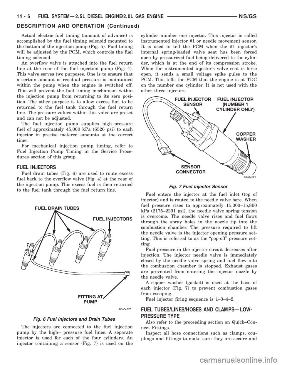
FUEL INJECTORS
Fuel drain tubes (Fig. 6) are used to route excess
fuel back to the overflow valve (Fig. 4) at the rear of
the injection pump. This excess fuel is then returned
to the fuel tank through the fuel return line.
The injectors are connected to the fuel injection
pump by the high± pressure fuel lines. A separate
injector is used for each of the four cylinders. An
injector containing a sensor (Fig. 7) is used on thecylinder number one injector. This injector is called
instrumented injector #1 or needle movement sensor.
It is used to tell the PCM when the #1 injector's
internal spring-loaded valve seat has been forced
open by pressurized fuel being delivered to the cylin-
der, which is at the end of its compression stroke.
When the instrumented injector's valve seat is force
open, it sends a small voltage spike pulse to the
PCM. This tells the PCM that the engine is at TDC
on the number one cylinder. It is not used with the
other three injectors.
Fuel enters the injector at the fuel inlet (top of
injector) and is routed to the needle valve bore. When
fuel pressure rises to approximately 15,000±15,800
kPa (2175±2291 psi), the needle valve spring tension
is overcome. The needle valve rises and fuel flows
through the spray holes in the nozzle tip into the
combustion chamber. The pressure required to lift
the needle valve is the injector opening pressure set-
ting. This is referred to as the ªpop-offº pressure set-
ting.
Fuel pressure in the injector circuit decreases after
injection. The injector needle valve is immediately
closed by the needle valve spring and fuel flow into
the combustion chamber is stopped. Exhaust gases
are prevented from entering the injector nozzle by
the needle valve.
A copper washer (gasket) is used at the base of
each injector (Fig. 7) to prevent combustion gases
from escaping.
Fuel injector firing sequence is 1±3±4±2.
FUEL TUBES/LINES/HOSES AND CLAMPSÐLOW-
PRESSURE TYPE
Also refer to the proceeding section on Quick±Con-
nect Fittings.
Inspect all hose connections such as clamps, cou-
plings and fittings to make sure they are secure andFig. 6 Fuel Injectors and Drain Tubes
Fig. 7 Fuel Injector Sensor
14 - 6 FUEL SYSTEMÐ2.5L DIESEL ENGINE/2.0L GAS ENGINENS/GS
DESCRIPTION AND OPERATION (Continued)