1996 CHRYSLER VOYAGER sensor
[x] Cancel search: sensorPage 1674 of 1938
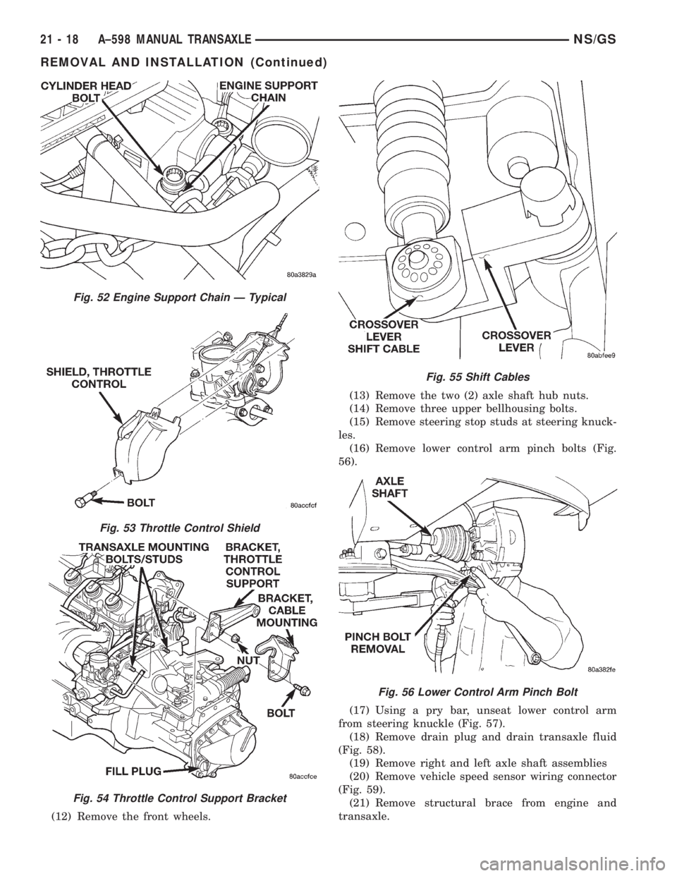
(12) Remove the front wheels.(13) Remove the two (2) axle shaft hub nuts.
(14) Remove three upper bellhousing bolts.
(15) Remove steering stop studs at steering knuck-
les.
(16) Remove lower control arm pinch bolts (Fig.
56).
(17) Using a pry bar, unseat lower control arm
from steering knuckle (Fig. 57).
(18) Remove drain plug and drain transaxle fluid
(Fig. 58).
(19) Remove right and left axle shaft assemblies
(20) Remove vehicle speed sensor wiring connector
(Fig. 59).
(21) Remove structural brace from engine and
transaxle.
Fig. 52 Engine Support Chain Ð Typical
Fig. 53 Throttle Control Shield
Fig. 54 Throttle Control Support Bracket
Fig. 55 Shift Cables
Fig. 56 Lower Control Arm Pinch Bolt
21 - 18 A±598 MANUAL TRANSAXLENS/GS
REMOVAL AND INSTALLATION (Continued)
Page 1675 of 1938
(22) Remove lower starter bolt.
(23) Remove engine wiring harness clip.
CAUTION: Always use a safety chain when remov-
ing or installing transaxle assembly.
(24) Place a transmission jack under the transmis-
sion
(25) Remove the transaxle lower dust cover.
(26) Remove the access cover in right splash shield
to access torsional damper bolt.
(27) Remove drive plate to modular clutch bolts
while holding torsional damper bolt with socket and
ratchet. To avoid distortion of the drive plate, remove
the modular clutch bolts a few turns at a time. Use a
crisscross pattern until all bolts are loosened.
(28) Unbolt rear engine mount through bolt and
two (2) mount bolts.
(29) Remove the left front fender splash shield.
(30) Unbolt left engine mount through bolt and
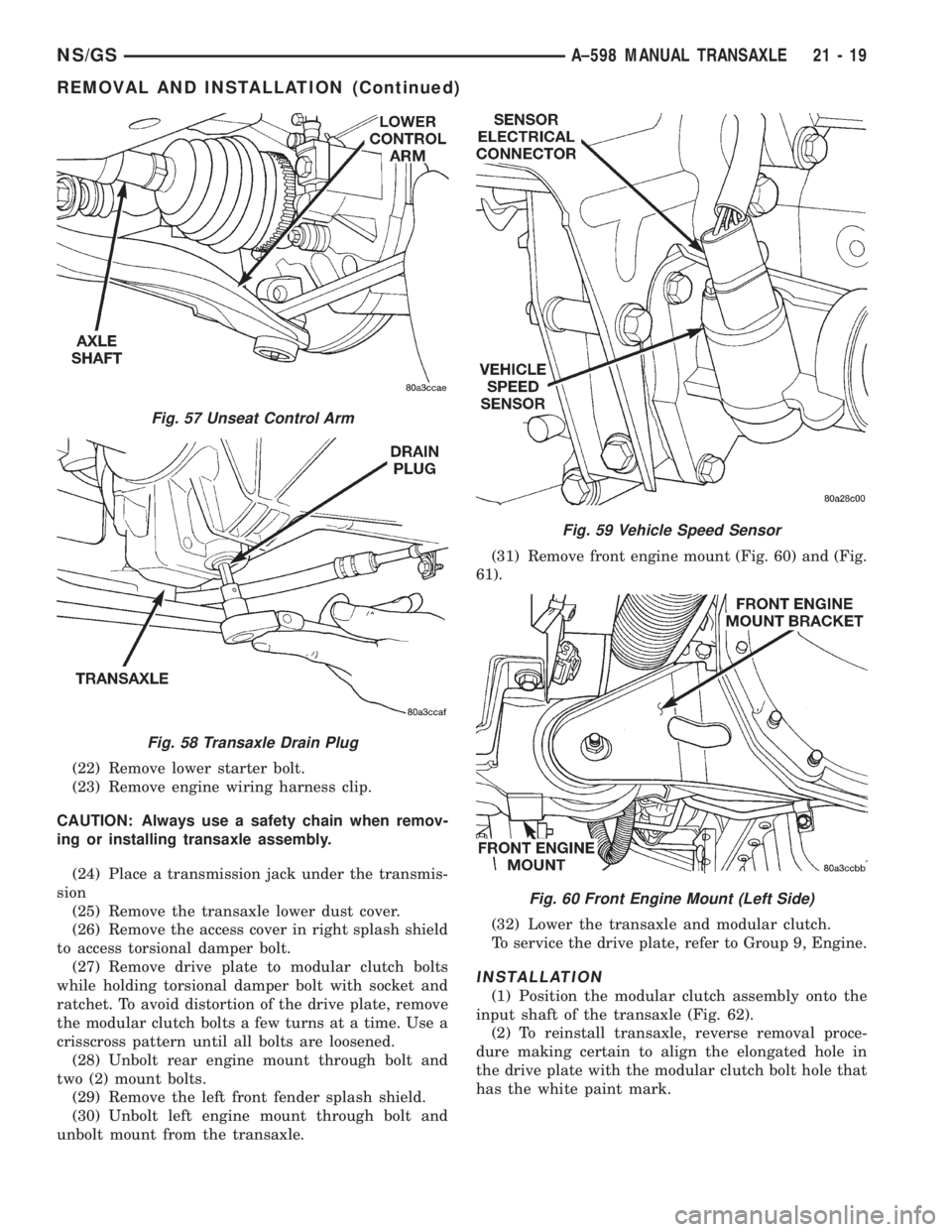
unbolt mount from the transaxle.(31) Remove front engine mount (Fig. 60) and (Fig.
61).
(32) Lower the transaxle and modular clutch.
To service the drive plate, refer to Group 9, Engine.
INSTALLATION
(1) Position the modular clutch assembly onto the
input shaft of the transaxle (Fig. 62).
(2) To reinstall transaxle, reverse removal proce-
dure making certain to align the elongated hole in
the drive plate with the modular clutch bolt hole that
has the white paint mark.
Fig. 57 Unseat Control Arm
Fig. 58 Transaxle Drain Plug
Fig. 59 Vehicle Speed Sensor
Fig. 60 Front Engine Mount (Left Side)
NS/GSA±598 MANUAL TRANSAXLE 21 - 19
REMOVAL AND INSTALLATION (Continued)
Page 1715 of 1938
(14) Apply a bead of MopartGasket Maker or
equivalent onto bearing support plate. Install bearing
support plate.
(15) Install necessary shim calculated from Step
12
(16) Install bearing retainer plate. Tighten bearing
retainer plate to 17 N´m (250 in. lbs.).
(17) Install 5th drive gear onto the input shaft.
(18) Install 5th gear, synchro, fork, and plate.
(19) Install 5th gear synchro snap ring.
(20) Install 5th gear shift fork roll pin.
(21) Use Special Tool 6252 to hold 5th gear and
install new 5th gear nut at input shaft. Tighten the
retaining nut to 176 N´m (130 ft. lbs.).
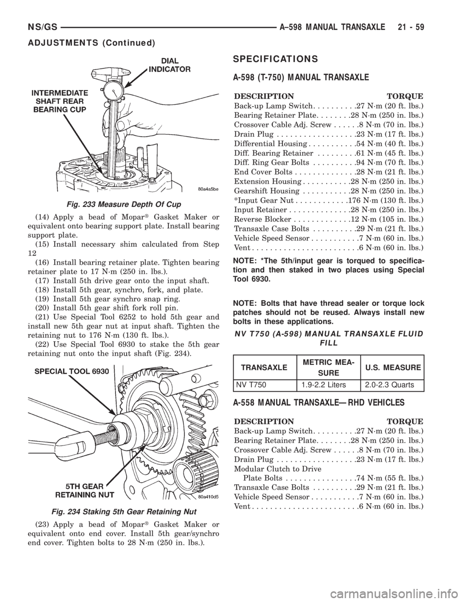
(22) Use Special Tool 6930 to stake the 5th gear
retaining nut onto the input shaft (Fig. 234).
(23) Apply a bead of MopartGasket Maker or
equivalent onto end cover. Install 5th gear/synchro
end cover. Tighten bolts to 28 N´m (250 in. lbs.).
SPECIFICATIONS
A-598 (T-750) MANUAL TRANSAXLE
DESCRIPTION TORQUE
Back-up Lamp Switch..........27N´m(20ft.lbs.)
Bearing Retainer Plate........28N´m(250 in. lbs.)
Crossover Cable Adj. Screw......8N´m(70in.lbs.)
Drain Plug..................23N´m(17ft.lbs.)
Differential Housing...........54N´m(40ft.lbs.)
Diff. Bearing Retainer.........61N´m(45ft.lbs.)
Diff. Ring Gear Bolts..........94N´m(70ft.lbs.)
End Cover Bolts..............28N´m(21ft.lbs.)
Extension Housing...........28N´m(250 in. lbs.)
Gearshift Housing...........28N´m(250 in. lbs.)
*Input Gear Nut............176 N´m (130 ft. lbs.)
Input Retainer..............28N´m(250 in. lbs.)
Reverse Blocker.............12N´m(105 in. lbs.)
Transaxle Case Bolts..........29N´m(21ft.lbs.)
Vehicle Speed Sensor...........7N´m(60in.lbs.)
Vent........................6N´m(60in.lbs.)
NOTE: *The 5th/input gear is torqued to specifica-
tion and then staked in two places using Special
Tool 6930.
NOTE: Bolts that have thread sealer or torque lock
patches should not be reused. Always install new
bolts in these applications.
A-558 MANUAL TRANSAXLEÐRHD VEHICLES
DESCRIPTION TORQUE
Back-up Lamp Switch..........27N´m(20ft.lbs.)
Bearing Retainer Plate........28N´m(250 in. lbs.)
Crossover Cable Adj. Screw......8N´m(70in.lbs.)
Drain Plug..................23N´m(17ft.lbs.)
Modular Clutch to Drive
Plate Bolts................74N´m(55ft.lbs.)
Transaxle Case Bolts..........29N´m(21ft.lbs.)
Vehicle Speed Sensor...........7N´m(60in.lbs.)
Vent........................6N´m(60in.lbs.)
Fig. 233 Measure Depth Of Cup
Fig. 234 Staking 5th Gear Retaining Nut
NV T750 (A-598) MANUAL TRANSAXLE FLUID
FILL
TRANSAXLEMETRIC MEA-
SUREU.S. MEASURE
NV T750 1.9-2.2 Liters 2.0-2.3 Quarts
NS/GSA±598 MANUAL TRANSAXLE 21 - 59
ADJUSTMENTS (Continued)
Page 1823 of 1938
DIAGNOSTICS
During the Actuator calibration, diagnostics are
performed on the actuators and evaporator tempera-
ture Fin Sensor. Once diagnostics are completed the
REAR WIPER and INTERMITTENT LED's will flash
to indicate either a successful calibration or the
appropriate fail code(s). At this time manual testing
of the Blend, Mode and Driver (if equipped) potenti-
ometers can be performed. If a failure is detected
during Diagnostics a fault will be set in the control.
When Ignition is cycled OFF and then ON or Diag-
nostics is aborted, the REAR WIPER and INTER-
MITTENT LED's will flash simultaneously showing
that a failure has occurred. The control will not indi-
cate the fail code, but only that a failure had
occurred during the last diagnostics test. The only
way to clear the failure codes is repeat the Calibra-
tion Diagnostic and Cooldown test, after all repairs
are completed.
COOLDOWN TEST
This test has been designed for performance test-
ing of the A/C system at the manufacturing facility. If
the HVAC control module is replaced, the Cooldown
test will occur during Calibration test. Cooldown will
not occur on Heater Only units. During the Cooldown
test the control will monitor the temperature of the
Fin Sensor. The A/C system must be able to bring the
evaporator temperature down a predetermined mini-
mum amount in less than 2 minutes.
CALIBRATION/COOLDOWN LED DISPLAY
CODES
See table for definition of flashing LED's. If no
problems are found, the control functions normally.
CALIBRATION/DIAGNOSTICS TEST ENTRY
TO INITIATE TESTS:
²Set Blower motor ON HIGH
²Set Mode position to Panel
²Open all A/C outlets
²Set Temperature to Cold (Both slide pots if
equipped)
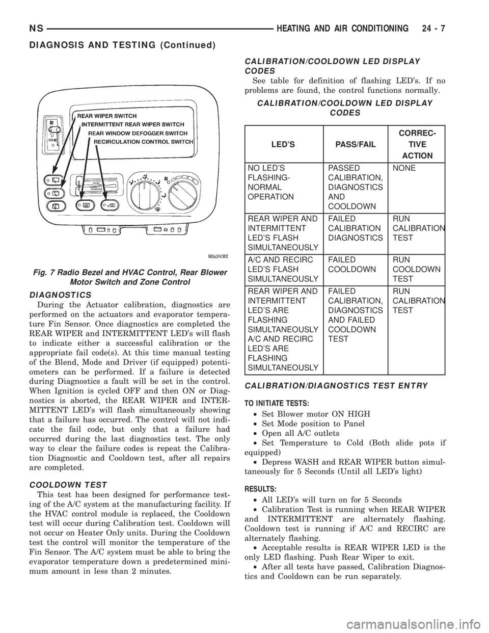
²Depress WASH and REAR WIPER button simul-
taneously for 5 Seconds (Until all LED's light)
RESULTS:
²All LED's will turn on for 5 Seconds
²Calibration Test is running when REAR WIPER
and INTERMITTENT are alternately flashing.
Cooldown test is running if A/C and RECIRC are
alternately flashing.
²Acceptable results is REAR WIPER LED is the
only LED flashing. Push Rear Wiper to exit.
²After all tests have passed, Calibration Diagnos-
tics and Cooldown can be run separately.
Fig. 7 Radio Bezel and HVAC Control, Rear Blower
Motor Switch and Zone Control
CALIBRATION/COOLDOWN LED DISPLAY
CODES
LED'S PASS/FAILCORREC-
TIVE
ACTION
NO LED'S
FLASHING-
NORMAL
OPERATIONPASSED
CALIBRATION,
DIAGNOSTICS
AND
COOLDOWNNONE
REAR WIPER AND
INTERMITTENT
LED'S FLASH
SIMULTANEOUSLYFAILED
CALIBRATION
DIAGNOSTICSRUN
CALIBRATION
TEST
A/C AND RECIRC
LED'S FLASH
SIMULTANEOUSLYFAILED
COOLDOWNRUN
COOLDOWN
TEST
REAR WIPER AND
INTERMITTENT
LED'S ARE
FLASHING
SIMULTANEOUSLY
A/C AND RECIRC
LED'S ARE
FLASHING
SIMULTANEOUSLYFAILED
CALIBRATION,
DIAGNOSTICS
AND FAILED
COOLDOWN
TESTRUN
CALIBRATION
TEST
NSHEATING AND AIR CONDITIONING 24 - 7
DIAGNOSIS AND TESTING (Continued)
Page 1824 of 1938
COOLDOWN TEST ENTRY
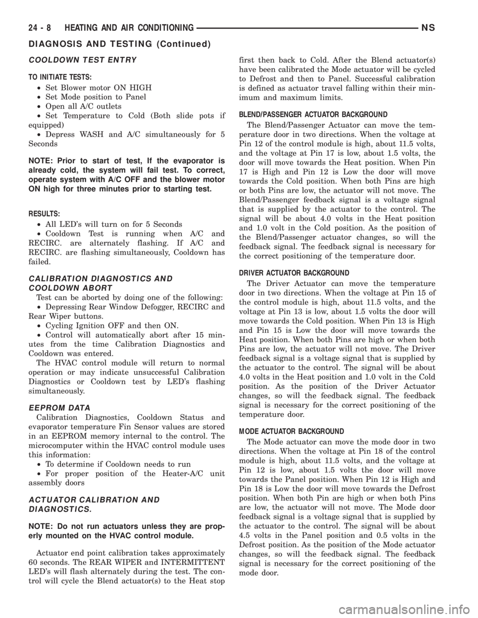
TO INITIATE TESTS:
²Set Blower motor ON HIGH
²Set Mode position to Panel
²Open all A/C outlets
²Set Temperature to Cold (Both slide pots if
equipped)
²Depress WASH and A/C simultaneously for 5
Seconds
NOTE: Prior to start of test, If the evaporator is
already cold, the system will fail test. To correct,
operate system with A/C OFF and the blower motor
ON high for three minutes prior to starting test.
RESULTS:
²All LED's will turn on for 5 Seconds
²Cooldown Test is running when A/C and
RECIRC. are alternately flashing. If A/C and
RECIRC. are flashing simultaneously, Cooldown has
failed.
CALIBRATION DIAGNOSTICS AND
COOLDOWN ABORT
Test can be aborted by doing one of the following:
²Depressing Rear Window Defogger, RECIRC and
Rear Wiper buttons.
²Cycling Ignition OFF and then ON.
²Control will automatically abort after 15 min-
utes from the time Calibration Diagnostics and
Cooldown was entered.
The HVAC control module will return to normal
operation or may indicate unsuccessful Calibration
Diagnostics or Cooldown test by LED's flashing
simultaneously.
EEPROM DATA
Calibration Diagnostics, Cooldown Status and
evaporator temperature Fin Sensor values are stored
in an EEPROM memory internal to the control. The
microcomputer within the HVAC control module uses
this information:
²To determine if Cooldown needs to run
²For proper position of the Heater-A/C unit
assembly doors
ACTUATOR CALIBRATION AND
DIAGNOSTICS.
NOTE: Do not run actuators unless they are prop-
erly mounted on the HVAC control module.
Actuator end point calibration takes approximately
60 seconds. The REAR WIPER and INTERMITTENT
LED's will flash alternately during the test. The con-
trol will cycle the Blend actuator(s) to the Heat stopfirst then back to Cold. After the Blend actuator(s)
have been calibrated the Mode actuator will be cycled
to Defrost and then to Panel. Successful calibration
is defined as actuator travel falling within their min-
imum and maximum limits.
BLEND/PASSENGER ACTUATOR BACKGROUND
The Blend/Passenger Actuator can move the tem-
perature door in two directions. When the voltage at
Pin 12 of the control module is high, about 11.5 volts,
and the voltage at Pin 17 is low, about 1.5 volts, the
door will move towards the Heat position. When Pin
17 is High and Pin 12 is Low the door will move
towards the Cold position. When both Pins are high
or both Pins are low, the actuator will not move. The
Blend/Passenger feedback signal is a voltage signal
that is supplied by the actuator to the control. The
signal will be about 4.0 volts in the Heat position
and 1.0 volt in the Cold position. As the position of
the Blend/Passenger actuator changes, so will the
feedback signal. The feedback signal is necessary for
the correct positioning of the temperature door.
DRIVER ACTUATOR BACKGROUND
The Driver Actuator can move the temperature
door in two directions. When the voltage at Pin 15 of
the control module is high, about 11.5 volts, and the
voltage at Pin 13 is low, about 1.5 volts the door will
move towards the Cold position. When Pin 13 is High
and Pin 15 is Low the door will move towards the
Heat position. When both Pins are high or when both
Pins are low, the actuator will not move. The Driver
feedback signal is a voltage signal that is supplied by
the actuator to the control. The signal will be about
4.0 volts in the Heat position and 1.0 volt in the Cold
position. As the position of the Driver Actuator
changes, so will the feedback signal. The feedback
signal is necessary for the correct positioning of the
temperature door.
MODE ACTUATOR BACKGROUND
The Mode actuator can move the mode door in two
directions. When the voltage at Pin 18 of the control
module is high, about 11.5 volts, and the voltage at
Pin 12 is low, about 1.5 volts the door will move
towards the Panel position. When Pin 12 is High and
Pin 18 is Low the door will move towards the Defrost
position. When both Pin are high or when both Pins
are low, the actuator will not move. The Mode door
feedback signal is a voltage signal that is supplied by
the actuator to the control. The signal will be about
4.5 volts in the Panel position and 0.5 volts in the
Defrost position. As the position of the Mode actuator
changes, so will the feedback signal. The feedback
signal is necessary for the correct positioning of the
mode door.
24 - 8 HEATING AND AIR CONDITIONINGNS
DIAGNOSIS AND TESTING (Continued)
Page 1825 of 1938
FAIL CODES/LEVEL DISPLAY
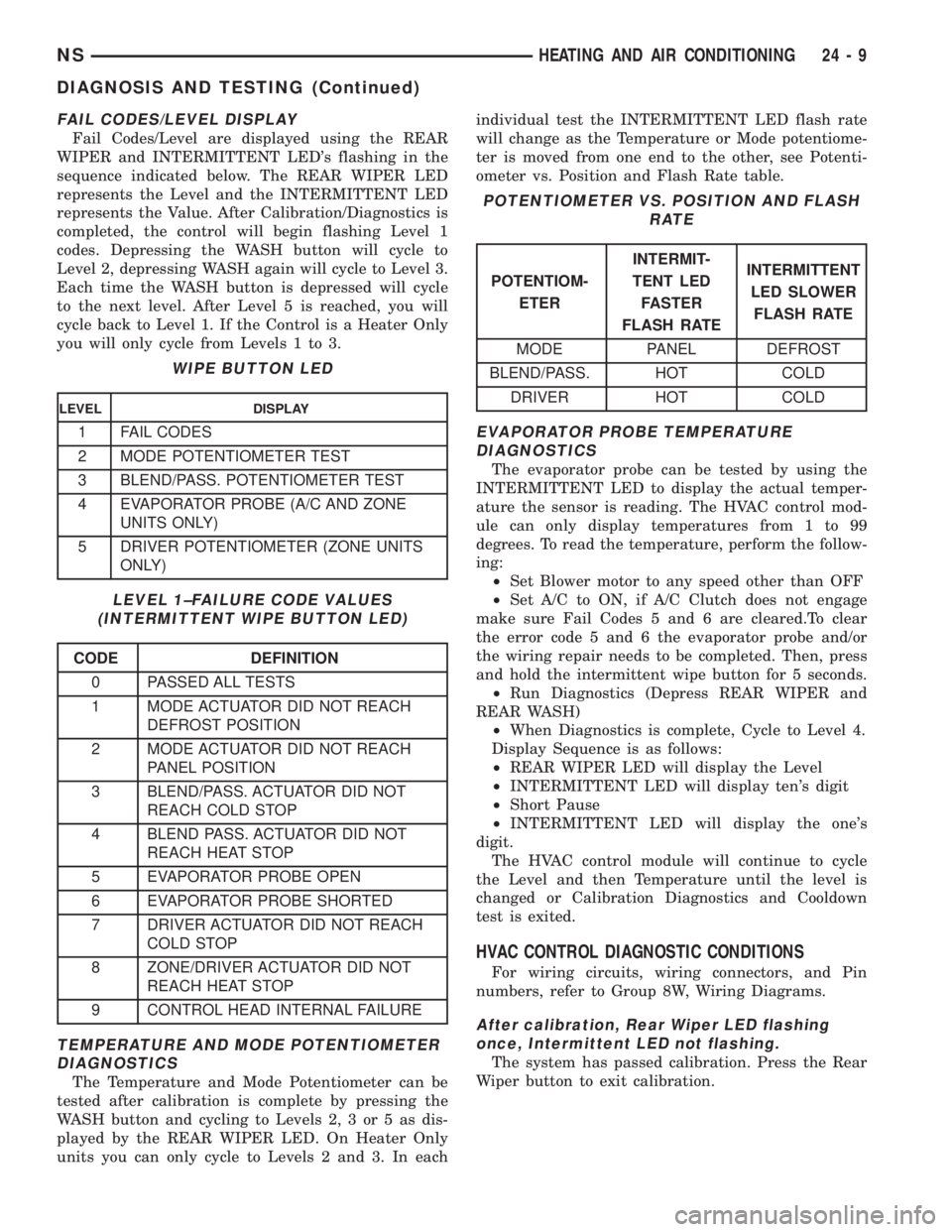
Fail Codes/Level are displayed using the REAR
WIPER and INTERMITTENT LED's flashing in the
sequence indicated below. The REAR WIPER LED
represents the Level and the INTERMITTENT LED
represents the Value. After Calibration/Diagnostics is
completed, the control will begin flashing Level 1
codes. Depressing the WASH button will cycle to
Level 2, depressing WASH again will cycle to Level 3.
Each time the WASH button is depressed will cycle
to the next level. After Level 5 is reached, you will
cycle back to Level 1. If the Control is a Heater Only
you will only cycle from Levels 1 to 3.
TEMPERATURE AND MODE POTENTIOMETER
DIAGNOSTICS
The Temperature and Mode Potentiometer can be
tested after calibration is complete by pressing the
WASH button and cycling to Levels 2, 3 or 5 as dis-
played by the REAR WIPER LED. On Heater Only
units you can only cycle to Levels 2 and 3. In eachindividual test the INTERMITTENT LED flash rate
will change as the Temperature or Mode potentiome-
ter is moved from one end to the other, see Potenti-
ometer vs. Position and Flash Rate table.
EVAPORATOR PROBE TEMPERATURE
DIAGNOSTICS
The evaporator probe can be tested by using the
INTERMITTENT LED to display the actual temper-
ature the sensor is reading. The HVAC control mod-
ule can only display temperatures from 1 to 99
degrees. To read the temperature, perform the follow-
ing:
²Set Blower motor to any speed other than OFF
²Set A/C to ON, if A/C Clutch does not engage
make sure Fail Codes 5 and 6 are cleared.To clear
the error code 5 and 6 the evaporator probe and/or
the wiring repair needs to be completed. Then, press
and hold the intermittent wipe button for 5 seconds.
²Run Diagnostics (Depress REAR WIPER and
REAR WASH)
²When Diagnostics is complete, Cycle to Level 4.
Display Sequence is as follows:
²REAR WIPER LED will display the Level
²INTERMITTENT LED will display ten's digit
²Short Pause
²INTERMITTENT LED will display the one's
digit.
The HVAC control module will continue to cycle
the Level and then Temperature until the level is
changed or Calibration Diagnostics and Cooldown
test is exited.
HVAC CONTROL DIAGNOSTIC CONDITIONS
For wiring circuits, wiring connectors, and Pin
numbers, refer to Group 8W, Wiring Diagrams.
After calibration, Rear Wiper LED flashing
once, Intermittent LED not flashing.
The system has passed calibration. Press the Rear
Wiper button to exit calibration.
WIPE BUTTON LED
LEVEL DISPLAY
1 FAIL CODES
2 MODE POTENTIOMETER TEST
3 BLEND/PASS. POTENTIOMETER TEST
4 EVAPORATOR PROBE (A/C AND ZONE
UNITS ONLY)
5 DRIVER POTENTIOMETER (ZONE UNITS
ONLY)
LEVEL 1±FAILURE CODE VALUES
(INTERMITTENT WIPE BUTTON LED)
CODE DEFINITION
0 PASSED ALL TESTS
1 MODE ACTUATOR DID NOT REACH
DEFROST POSITION
2 MODE ACTUATOR DID NOT REACH
PANEL POSITION
3 BLEND/PASS. ACTUATOR DID NOT
REACH COLD STOP
4 BLEND PASS. ACTUATOR DID NOT
REACH HEAT STOP
5 EVAPORATOR PROBE OPEN
6 EVAPORATOR PROBE SHORTED
7 DRIVER ACTUATOR DID NOT REACH
COLD STOP
8 ZONE/DRIVER ACTUATOR DID NOT
REACH HEAT STOP
9 CONTROL HEAD INTERNAL FAILURE
POTENTIOMETER VS. POSITION AND FLASH
RATE
POTENTIOM-
ETERINTERMIT-
TENT LED
FASTER
FLASH RATEINTERMITTENT
LED SLOWER
FLASH RATE
MODE PANEL DEFROST
BLEND/PASS. HOT COLD
DRIVER HOT COLD
NSHEATING AND AIR CONDITIONING 24 - 9
DIAGNOSIS AND TESTING (Continued)
Page 1827 of 1938

After calibration, Rear Wiper LED flashing
once, Intermittent LED flashing six times. The
evaporator probe is shorted.
(1) Using a voltmeter, check Pin 1 of the evapora-
tor probe wiring connector for 0.1 - 4.75 volts. If OK,
go to Step 2. If less than 0.1 volts, check for loose or
corroded connector, open or shorted circuit and repair
as necessary.
(2) Using a ohmmeter, check Pin 2 for a good
ground, If OK, go to Step 3. If not OK, check for
shorted circuit and repair as necessary.
(3) If ground and power circuit are OK, replace
Evaporator Probe
(4) Once repairs are completed, press the intermit-
tent button about 5 seconds until all LED's light to
remove fault code from memory. Then repeat the Cal-
ibration Diagnostic and Cooldown test. Repeating the
test is necessary to clear the fault codes.
After calibration, Rear Wiper LED flashing
once, Intermittent LED flashing seven times.
The Driver's temperature actuator on a zone
system did not reach cold stop.
(1) Check if the correct HVAC control module was
used.
(2) Using a voltmeter, check at the temperature
door actuator wiring connector, check Pin 1 for bat-
tery voltage. Move the HVAC control from cold to the
hot position, check Pin 4 voltage it should change
from 0.5 - 1.5 volts 3.5 - 4.5 volts. If voltage is OK, go
to Step 3. If not OK, check for loose or corroded con-
nector, open or shorted circuit and repair as neces-
sary.
(3) Remove actuator, and check if the gear pins are
in the correct track on cam or if they are binding. If
OK, go to Step 4. If not OK, repair as necessary.
(4) Check for binding doors, if door are binding
repair as necessary. If gears and door are OK, replace
actuator.
(5) Once repairs are completed repeat the Calibra-
tion Diagnostic and Cooldown test. Repeating the
test is necessary to clear the fault codes.
After calibration, Rear Wiper LED flashing
once, Intermittent LED flashing eight times.
The Driver's temperature actuator on a zone
system did not reach hot stop.
(1) Check if the correct HVAC control module was
used.
(2) Using a voltmeter, check at the temperature
door actuator wiring connector, check Pin 1 for bat-
tery voltage. Move the HVAC control from hot to cold
position, Pin 4 voltage it should change from 3.5 - 4.5
volts to 0.5 - 1.5 volts. If voltage is OK, go to Step 3.
If not OK, check for loose or corroded connector, open
or shorted circuit and repair as necessary.(3) Remove actuator, and check if the gear pins are
in the correct track on cam or if they are binding. If
OK, go to Step 4. If not OK, repair as necessary.
(4) Check for binding door, if door is binding repair
as necessary. If gears and door are OK, replace
actuator.
(5) Once repairs are completed repeat the Calibra-
tion Diagnostic and Cooldown test. Repeating the
test is necessary to clear the fault codes.
After calibration, Rear Wiper LED flashing
once, Intermittent LED flashing nine times.
The HVAC control module, has a internal
failure.
(1) Replace the HVAC control module.
(2) Once repairs are completed repeat the Calibra-
tion Diagnostic and Cooldown test. Repeating the
test is necessary to clear the fault codes.
After calibration and testing the A/C and
RECIRC LED flashing simultaneously. Failed
Cooldown test.
(1) Determine if the refrigerant system is operat-
ing correctly:
²Check the outlet air temperature
²Feel the compressor suction plumbing, is it hot?
(2) If not OK, go to Step 3. If OK, repeat the Cal-
ibration Diagnostic and Cooldown test.
(3) If system does not seem to be operating cor-
rectly, perform diagnostics for poor performance:
²Low refrigerant charge
²No charge
²Compressor not operating
Verify that the test was done with the evaporator
at room temperature. The test consists of starting
the compressor and measuring the time it takes for
the evaporator temperature to fall 7ÉC (20ÉF). If the
compressor has been running, the evaporator is cold
already and will not be capable of falling 7ÉC (20ÉF).
If the test was run with a cold evaporator, turn A/C
off and turn the blower motor switch to high position
for 3 to 5 minutes till the evaporator is to room tem-
perature. Then repeat the Calibration Diagnostic and
Cooldown test.
If refrigerant system is performing properly and
the system will not pass test. Repeat the Calibration
Diagnostic and Cooldown test to determine if the
evaporator temperature FIN sensor has developed an
open or a short circuit. If the HVAC control module
still passes Calibration test, verify Cooldown test
manually with a pocket thermometer. The outlet air
temperature must drop at least 7ÉC (20ÉF) within
two minutes. If the vehicle passes with the manual
thermometer, take HVAC control to level 4 (evapora-
tor probe temperature readout) and repeat the
Cooldown test. Ensure the evaporator is at room tem-
perature before starting test. Check if evaporator
NSHEATING AND AIR CONDITIONING 24 - 11
DIAGNOSIS AND TESTING (Continued)
Page 1828 of 1938
probe will drop the temperature 7ÉC (20ÉF) in two
minutes. If the Evaporator Probe is found to be
faulty, check that the sensor is positioned in the
evaporator fins properly. If not, correct and repeat
test. If OK, replace the evaporator probe.
Once the repairs are completed, repeat the Calibra-
tion Diagnostic and Cooldown test. Repeating the
test is necessary to clear the fault codes.
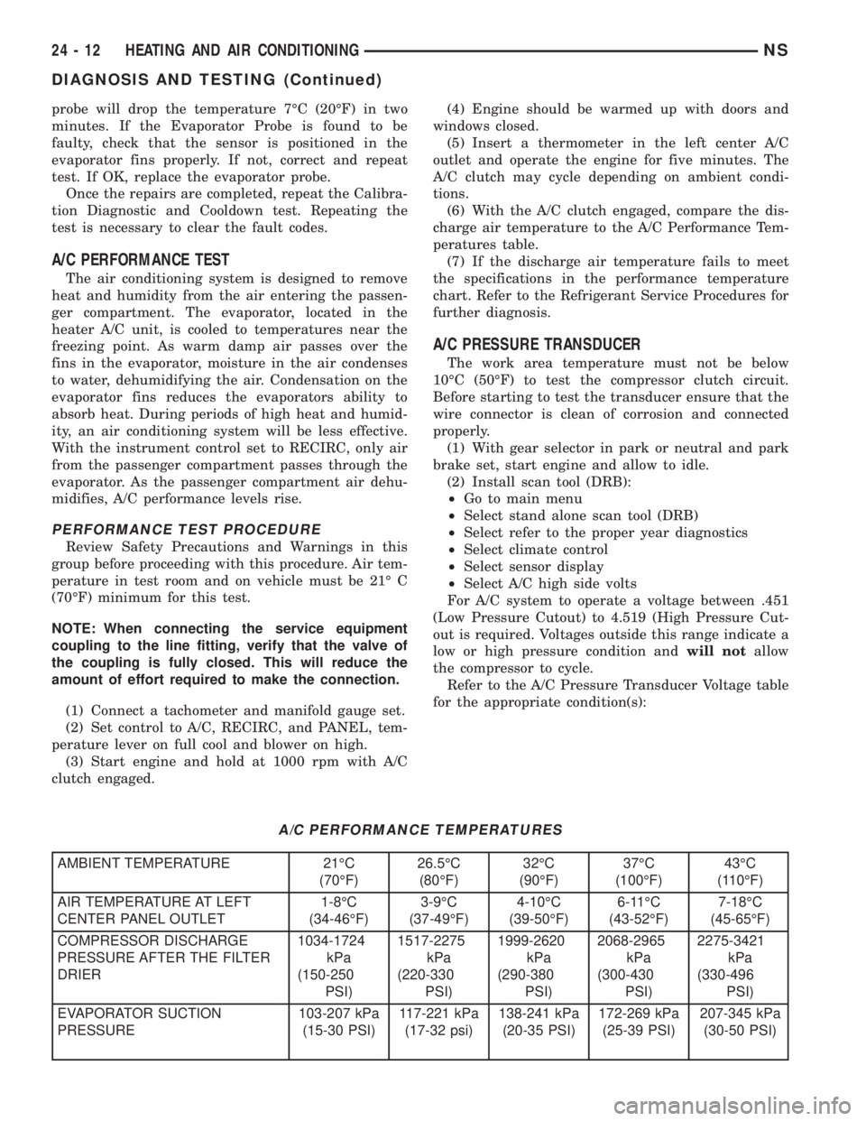
A/C PERFORMANCE TEST
The air conditioning system is designed to remove
heat and humidity from the air entering the passen-
ger compartment. The evaporator, located in the
heater A/C unit, is cooled to temperatures near the
freezing point. As warm damp air passes over the
fins in the evaporator, moisture in the air condenses
to water, dehumidifying the air. Condensation on the
evaporator fins reduces the evaporators ability to
absorb heat. During periods of high heat and humid-
ity, an air conditioning system will be less effective.
With the instrument control set to RECIRC, only air
from the passenger compartment passes through the
evaporator. As the passenger compartment air dehu-
midifies, A/C performance levels rise.
PERFORMANCE TEST PROCEDURE
Review Safety Precautions and Warnings in this
group before proceeding with this procedure. Air tem-
perature in test room and on vehicle must be 21É C
(70ÉF) minimum for this test.
NOTE: When connecting the service equipment
coupling to the line fitting, verify that the valve of
the coupling is fully closed. This will reduce the
amount of effort required to make the connection.
(1) Connect a tachometer and manifold gauge set.
(2) Set control to A/C, RECIRC, and PANEL, tem-
perature lever on full cool and blower on high.
(3) Start engine and hold at 1000 rpm with A/C
clutch engaged.(4) Engine should be warmed up with doors and
windows closed.
(5) Insert a thermometer in the left center A/C
outlet and operate the engine for five minutes. The
A/C clutch may cycle depending on ambient condi-
tions.
(6) With the A/C clutch engaged, compare the dis-
charge air temperature to the A/C Performance Tem-
peratures table.
(7) If the discharge air temperature fails to meet
the specifications in the performance temperature
chart. Refer to the Refrigerant Service Procedures for
further diagnosis.
A/C PRESSURE TRANSDUCER
The work area temperature must not be below
10ÉC (50ÉF) to test the compressor clutch circuit.
Before starting to test the transducer ensure that the
wire connector is clean of corrosion and connected
properly.
(1) With gear selector in park or neutral and park
brake set, start engine and allow to idle.
(2) Install scan tool (DRB):
²Go to main menu
²Select stand alone scan tool (DRB)
²Select refer to the proper year diagnostics
²Select climate control
²Select sensor display
²Select A/C high side volts
For A/C system to operate a voltage between .451
(Low Pressure Cutout) to 4.519 (High Pressure Cut-
out is required. Voltages outside this range indicate a
low or high pressure condition andwill notallow
the compressor to cycle.
Refer to the A/C Pressure Transducer Voltage table
for the appropriate condition(s):
A/C PERFORMANCE TEMPERATURES
AMBIENT TEMPERATURE 21ÉC
(70ÉF)26.5ÉC
(80ÉF)32ÉC
(90ÉF)37ÉC
(100ÉF)43ÉC
(110ÉF)
AIR TEMPERATURE AT LEFT
CENTER PANEL OUTLET1-8ÉC
(34-46ÉF)3-9ÉC
(37-49ÉF)4-10ÉC
(39-50ÉF)6-11ÉC
(43-52ÉF)7-18ÉC
(45-65ÉF)
COMPRESSOR DISCHARGE
PRESSURE AFTER THE FILTER
DRIER1034-1724
kPa
(150-250
PSI)1517-2275
kPa
(220-330
PSI)1999-2620
kPa
(290-380
PSI)2068-2965
kPa
(300-430
PSI)2275-3421
kPa
(330-496
PSI)
EVAPORATOR SUCTION
PRESSURE103-207 kPa
(15-30 PSI)117-221 kPa
(17-32 psi)138-241 kPa
(20-35 PSI)172-269 kPa
(25-39 PSI)207-345 kPa
(30-50 PSI)
24 - 12 HEATING AND AIR CONDITIONINGNS
DIAGNOSIS AND TESTING (Continued)