1996 CHRYSLER VOYAGER engine oil
[x] Cancel search: engine oilPage 1660 of 1938
²Improper operation
HARD SHIFTING
Hard shifting may be caused by a misadjusted
crossover cable. If hard shifting is accompanied by
gear clash, synchronizer clutch and stop rings or gear
teeth may be worn or damaged.
Misassembled synchronizer components also cause
shifting problems. Incorrectly installed synchronizer
sleeves, struts, or springs can cause shift problems.
NOISY OPERATION
Transaxle noise is most often a result of worn or
damaged components. Chipped, broken gear or syn-
chronizer teeth, and brinnelled, spalled bearings all
cause noise.
Abnormal wear and damage to the internal compo-
nents is frequently the end result of insufficient
lubricant.
SLIPS OUT OF GEAR
Transaxle disengagement may be caused by mis-
aligned or damaged shift components, or worn teeth
on the drive gears or synchronizer components. Incor-
rect assembly also causes gear disengagement.
LOW LUBRICANT LEVEL
Insufficient transaxle lubricant is usually the
result of leaks, or inaccurate fluid level check or refill
method. Leakage is evident by the presence of oil
around the leak point. If leakage is not evident, the
condition is probably the result of an underfill.
If air±powered lubrication equipment is used to fill
a transaxle, be sure the equipment is properly cali-
brated. Equipment out of calibration can lead to an
underfill condition.
The transaxle fill plug is located on the lower left
side of the transaxle end cover. With the vehicle at a
level position, remove the fill plug and check the
level of the lubricant. The lubricant level should be
within 3.175mm (1/8 inch) from the bottom of the fill
hole. If the lubricant level is low, fill the transaxle to
the bottom of the fill hole with SAE 5W-30 engine oil,
meeting SG and/or SG-CD qualifications, as the fac-
tory fill lubricant. SAE GL5 10W-40 engine oil is a
suitable service fill alternative.
CLUTCH PROBLEMS
Worn, damaged, or misaligned clutch components
can cause difficult shifting, gear clash, and noise.
A worn or damaged clutch disc, pressure plate, or
release bearing can cause hard shifting and gear
clash.
SERVICE PROCEDURES
FLUID DRAIN AND FILL
TRANSAXLE FLUID DRAIN
(1) Hoist vehicle.
(2) Install a drain pan underneath the transaxle
drain plug.
(3) Remove the transaxle drain plug. The drain
plug is located on the bottom of the transaxle hous-
ing.
(4) Let fluid drain out till there is just an occa-
sional drip.
(5) Reinstall drain plug. Tighten drain plug to 28
N´m (250 in. lbs.)
TRANSAXLE FLUID FILL
NOTE: All A-598 transaxles are equipped with a fill
plug. The fill plug is located on the end cover side
of the transaxle.
(1) Remove transaxle fill plug
The fluid level should be within 3.175mm (1/8
inch) from the bottom of the transaxle fill hole (vehi-
cle must be level when checking).
(2) Fill transaxle to proper level with SAE 5W-30
engine oil, meeting SG and/or SG-CD qualifications.
G5 SAE 10W-40 engine oil is a suitable service fill
alternative. Dry fill lubricant capacity is approxi-
mately 1.9-2.2 liters (4.0-4.6 pints)..
(3) Wipe the outside of the transaxle if any lubri-
cant spills.
(4) Reinstall transaxle fill plug.
FLUID DRAIN AND FILLÐRHD VEHICLES
TRANSAXLE FLUID DRAIN
(1) Hoist vehicle.
(2) Install a drain pan underneath the transaxle
drain plug.
(3) Remove the transaxle drain plug. The drain
plug is located on the bottom of the transaxle hous-
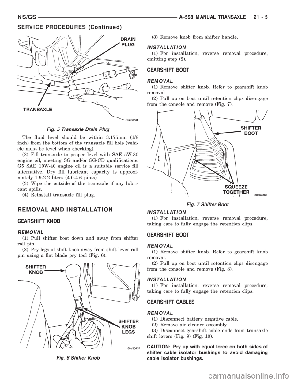
ing (Fig. 5).
(4) Let fluid drain out till there is just an occa-
sional drip.
(5) Reinstall drain plug. Tighten drain plug to 28
N´m (250 in. lbs.)
TRANSAXLE FLUID FILL
NOTE: All A-558 transaxles are equipped with a fill
plug. The fill plug is located on the end cover side
of the transaxle.
(1) Remove transaxle fill plug
21 - 4 A±598 MANUAL TRANSAXLENS/GS
DIAGNOSIS AND TESTING (Continued)
Page 1661 of 1938
The fluid level should be within 3.175mm (1/8
inch) from the bottom of the transaxle fill hole (vehi-
cle must be level when checking).
(2) Fill transaxle to proper level with SAE 5W-30
engine oil, meeting SG and/or SG-CD qualifications.
G5 SAE 10W-40 engine oil is a suitable service fill
alternative. Dry fill lubricant capacity is approxi-
mately 1.9-2.2 liters (4.0-4.6 pints).
(3) Wipe the outside of the transaxle if any lubri-
cant spills.
(4) Reinstall transaxle fill plug.
REMOVAL AND INSTALLATION
GEARSHIFT KNOB
REMOVAL
(1) Pull shifter boot down and away from shifter
roll pin.
(2) Pry legs of shift knob away from shift lever roll
pin using a flat blade pry tool (Fig. 6).(3) Remove knob from shifter handle.
INSTALLATION
(1) For installation, reverse removal procedure,
omitting step (2).
GEARSHIFT BOOT
REMOVAL
(1) Remove shifter knob. Refer to gearshift knob
removal.
(2) Pull up on boot until retention clips disengage
from the console and remove (Fig. 7).
INSTALLATION
(1) For installation, reverse removal procedure,
taking care to fully engage the retention clips.
GEARSHIFT BOOT
REMOVAL
(1) Remove shifter knob. Refer to gearshift knob
removal.
(2) Pull up on boot until retention clips disengage
from the console and remove (Fig. 8).
INSTALLATION
(1) For installation, reverse removal procedure,
taking care to fully engage the retention clips.
GEARSHIFT CABLES
REMOVAL
(1) Disconnect battery negative cable.
(2) Remove air cleaner assembly.
(3) Disconnect gearshift cable ends from transaxle
shift levers (Fig. 9) (Fig. 10).
CAUTION: Pry up with equal force on both sides of
shifter cable isolator bushings to avoid damaging
cable isolator bushings.
Fig. 5 Transaxle Drain Plug
Fig. 6 Shifter Knob
Fig. 7 Shifter Boot
NS/GSA±598 MANUAL TRANSAXLE 21 - 5
SERVICE PROCEDURES (Continued)
Page 1716 of 1938
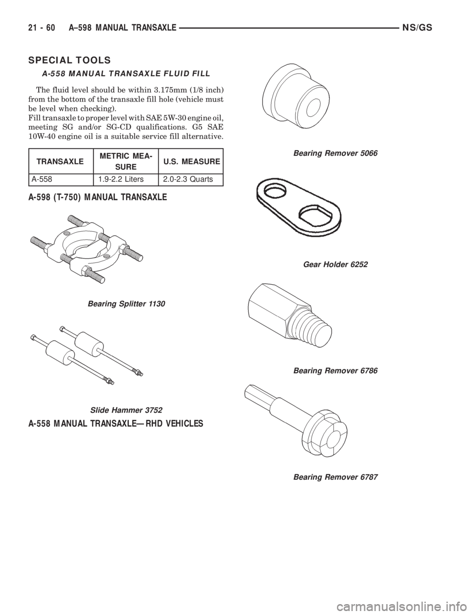
SPECIAL TOOLS
A-598 (T-750) MANUAL TRANSAXLE
A-558 MANUAL TRANSAXLEÐRHD VEHICLES
A-558 MANUAL TRANSAXLE FLUID FILL
The fluid level should be within 3.175mm (1/8 inch)
from the bottom of the transaxle fill hole (vehicle must
be level when checking).
Fill transaxle to proper level with SAE 5W-30 engine oil,
meeting SG and/or SG-CD qualifications. G5 SAE
10W-40 engine oil is a suitable service fill alternative.
TRANSAXLEMETRIC MEA-
SUREU.S. MEASURE
A-558 1.9-2.2 Liters 2.0-2.3 Quarts
Bearing Splitter 1130
Slide Hammer 3752
Bearing Remover 5066
Gear Holder 6252
Bearing Remover 6786
Bearing Remover 6787
21 - 60 A±598 MANUAL TRANSAXLENS/GS
Page 1732 of 1938
PAINT
INDEX
page page
GENERAL INFORMATION
AFTERMARKET PAINT REPAIR PRODUCTS.... 3
BASE COAT/CLEAR COAT FINISH............ 2PAINT CODE............................ 2
PAINTED SURFACE TOUCH-UP............. 2
WET SANDING, BUFFING, AND POLISHING.... 2
GENERAL INFORMATION
PAINT CODE
A paint code is provided on the body code plate
located in the engine compartment. Refer to the
Introduction section at the front of this manual for
body code plate description. The paint and trim codes
are also included on the Vehicle Safety Label located
on the driver's door end frame.
BASE COAT/CLEAR COAT FINISH
On most vehicles a two-part paint application (base
coat/clear coat) is used. Color paint that is applied to
primer is called base coat. The clear coat protects the
base coat from ultraviolet light and provides a dura-
ble high-gloss finish.
WET SANDING, BUFFING, AND POLISHING
Minor acid etching, orange peel, or smudging in
clear coat or single-stage finishes can be reduced
with light wet sanding, hand buffing, and polishing.
If the finish has been wet sanded in the past, it
cannot be repeated. Wet sanding operation
should be performed by a trained automotive
paint technician.
CAUTION: Do not remove clear coat finish, if
equipped. Base coat paint must retain clear coat for
durability.
PAINTED SURFACE TOUCH-UP
When a painted metal surface has been scratched
or chipped, it should be touched-up as soon as possi-
ble to avoid corrosion. For best results, use Mopart
Scratch Filler/Primer, Touch-Up Paints and Clear Top
Coat. Refer to Introduction group of this manual for
Body Code Plate information.
TOUCH-UP PROCEDURE
(1) Scrape loose paint and corrosion from inside
scratch or chip.
(2) Clean affected area with MopartTar/Road Oil
Remover, and allow to dry.
(3) Fill the inside of the scratch or chip with a coat
of filler/primer. Do not overlap primer onto good sur-
face finish. The applicator brush should be wet
enough to puddle-fill the defect without running. Do
not stroke brush applicator on body surface. Allow
the filler/primer to dry hard.
(4) Cover the filler/primer with color touch-up
paint. Do not overlap touch-up color onto the original
color coat around the scratch or chip. Butt the new
color to the original color, if possible. Do not stroke
applicator brush on body surface. Allow touch-up
paint to dry hard.
(5) On vehicles without clear coat, the touch-up
color can be lightly wet sanded (1500 grit) and pol-
ished with rubbing compound.
(6) On vehicles with clear coat, apply clear top coat
to touch-up paint with the same technique as
described in Step 4. Allow clear top coat to dry hard.
If desired, Step 5 can be performed on clear top coat.
23 - 2 BODYNS
Page 1817 of 1938
HEATING AND AIR CONDITIONING
CONTENTS
page page
FRONT HEATING AND AIR CONDITIONING
SYSTEM............................... 1REAR HEATING AND AIR CONDITIONING
SYSTEM.............................. 41
FRONT HEATING AND AIR CONDITIONING SYSTEM
INDEX
page page
GENERAL INFORMATION
INTRODUCTION......................... 2
SAFETY PRECAUTIONS AND WARNINGS...... 2
DESCRIPTION AND OPERATION
A/C PRESSURE TRANSDUCER.............. 2
A/C SERVICE PORTS..................... 2
AIR DISTRIBUTION DUCTS................. 2
COMPRESSOR HIGH-PRESSURE RELIEF
VALVE................................ 3
CONDENSATE DRAIN..................... 3
ENGINE COOLING SYSTEM REQUIREMENTS . . 3
EVAPORATOR PROBE..................... 3
HANDLING TUBING AND FITTINGS........... 3
HVAC CONTROL MODULE................. 4
REAR BLOWER SPEED SWITCH............ 3
SIDE DOOR HEATER A/C OUTLETS.......... 4
SIDE WINDOW DEMISTER................. 4
SYSTEM AIRFLOW....................... 4
SYSTEM OIL LEVEL...................... 5
DIAGNOSIS AND TESTING
A/C PERFORMANCE TEST................ 12
A/C PRESSURE TRANSDUCER............. 12
ACTUATOR CALIBRATION/DIAGNOSTICS AND
COOLDOWN TEST...................... 6
BLOWER MOTOR AND WHEEL ASSEMBLY.... 13
COMPRESSOR CLUTCH/COIL.............. 13
COMPRESSOR NOISE DIAGNOSIS.......... 13
EXPANSION VALVE...................... 13
HEATER PERFORMANCE TEST............ 15
HVAC CONTROL DIAGNOSTIC CONDITIONS . . . 9
SYSTEM CHARGE LEVEL TEST............ 16SERVICE PROCEDURES
CHARGING REFRIGERANT SYSTEM........ 17
EVACUATING REFRIGERANT SYSTEM....... 18
R-134a REFRIGERANT................... 16
STICKING HVAC CONTROL MODULE PUSH
BUTTONS............................ 19
SYSTEM LEAK CHECKING................ 19
THERMOCOUPLE PROBE................. 19
REMOVAL AND INSTALLATION
A/C PRESSURE TRANSDUCER............. 20
A/C SERVICE PORTS.................... 20
BLEND-AIR DOOR ACTUATOR............. 20
BLOWER MOTOR AND WHEEL ASSEMBLY.... 21
BLOWER MOTOR RESISTOR BLOCK........ 21
BLOWER MOTOR WHEEL................. 22
COMPRESSOR CLUTCH/COIL.............. 23
COMPRESSOR......................... 23
CONDENSER ASSEMBLY................. 25
DISCHARGE LINE....................... 26
EVAPORATOR PROBE.................... 27
EXPANSION VALVE...................... 28
FILTER-DRIER ASSEMBLY................. 28
HEATER A/C UNIT HOUSING............... 29
HEATER CORE......................... 30
HEATER HOSES........................ 31
LIQUID LINE........................... 32
MODE DOOR ACTUATOR................. 32
RECIRC DOOR ACTUATOR................ 34
SIDE WINDOW DEMISTER DUCTS.......... 33
SUCTION LINE.......................... 33
DISASSEMBLY AND ASSEMBLY
HEATER A/C UNIT RECONDITION........... 34
NSHEATING AND AIR CONDITIONING 24 - 1
Page 1818 of 1938
GENERAL INFORMATION
INTRODUCTION
Both the heater and the heater/air conditioning
systems share many of the same components. This
group will deal with both systems together when
component function is common, and separately when
they are not.
For proper operation of the instrument panel con-
trols, refer to the Owner's Manual provided with the
vehicle.
All vehicles are equipped with a common A/C-
heater unit housing assembly. When the vehicle has
only a heater system, the evaporator and recirculat-
ing air door are omitted.
An optional zone control HVAC unit is available.
This unit has dual blend-air doors that can be regu-
lated independently of each other. The temperature
setting can be different from driver's side to passen-
ger side. There is also a rear (aux.) heating and A/C
system available when the vehicle is equipped with
zone control.
SAFETY PRECAUTIONS AND WARNINGS
WARNING: WEAR EYE PROTECTION WHEN SER-
VICING THE AIR CONDITIONING REFRIGERANT
SYSTEM. SERIOUS EYE INJURY CAN RESULT
FROM EYE CONTACT WITH REFRIGERANT. IF EYE
CONTACT IS MADE, SEEK MEDICAL ATTENTION
IMMEDIATELY.
DO NOT EXPOSE REFRIGERANT TO OPEN
FLAME. POISONOUS GAS IS CREATED WHEN
REFRIGERANT IS BURNED. AN ELECTRONIC TYPE
LEAK DETECTOR IS RECOMMENDED.
LARGE AMOUNTS OF REFRIGERANT RELEASED
IN A CLOSED WORK AREA WILL DISPLACE THE
OXYGEN AND CAUSE SUFFOCATION.
THE EVAPORATION RATE OF REFRIGERANT AT
AVERAGE TEMPERATURE AND ALTITUDE IS
EXTREMELY HIGH. AS A RESULT, ANYTHING THAT
COMES IN CONTACT WITH THE REFRIGERANT
WILL FREEZE. ALWAYS PROTECT SKIN OR DELI-
CATE OBJECTS FROM DIRECT CONTACT WITH
REFRIGERANT. R-134a SERVICE EQUIPMENT OR
VEHICLE A/C SYSTEM SHOULD NOT BE PRES-
SURE TESTED OR LEAK TESTED WITH COM-
PRESSED AIR.
SOME MIXTURES OF AIR and R-134a HAVE BEEN
SHOWN TO BE COMBUSTIBLE AT ELEVATED
PRESSURES. THESE MIXTURES ARE POTENTIALLY
DANGEROUS AND MAY RESULT IN FIRE OR
EXPLOSION CAUSING INJURY OR PROPERTY
DAMAGE.
ANTIFREEZE IS AN ETHYLENE GLYCOL BASE
COOLANT AND IS HARMFUL IF SWALLOWED ORINHALED. SEEK MEDICAL ATTENTION IMMEDI-
ATELY IF SWALLOWED OR INHALED. DO NOT
STORE IN OPEN OR UNMARKED CONTAINERS.
WASH SKIN AND CLOTHING THOROUGHLY AFTER
COMING IN CONTACT WITH ETHYLENE GLYCOL.
KEEP OUT OF REACH OF CHILDREN AND PETS.
DO NOT OPEN A COOLING SYSTEM WHEN THE
ENGINE IS AT RUNNING TEMPERATURE. PER-
SONAL INJURY CAN RESULT.
CAUTION: The engine cooling system is designed
to develop internal pressure of 97 to 123 kPa (14 to
18 psi). Allow the vehicle to cool a minimum of 15
minutes before opening the cooling system. Refer
to Group 7, Cooling System.
DESCRIPTION AND OPERATION
AIR DISTRIBUTION DUCTS
The air distribution ducts for the A/C, Heater,
Defroster, and Second Seating Air Distribution are
not serviceable in vehicle. The procedures for service
of these ducts are covered in Group 8E, Instrument
Panel and Gauges.
The only ducts that are serviceable in the vehicle
are the side window demister ducts and the ducts
that feed the front door outlets for the first rear pas-
senger(s) seating. To service the door ducts refer to
Group 23, Body.
A/C PRESSURE TRANSDUCER
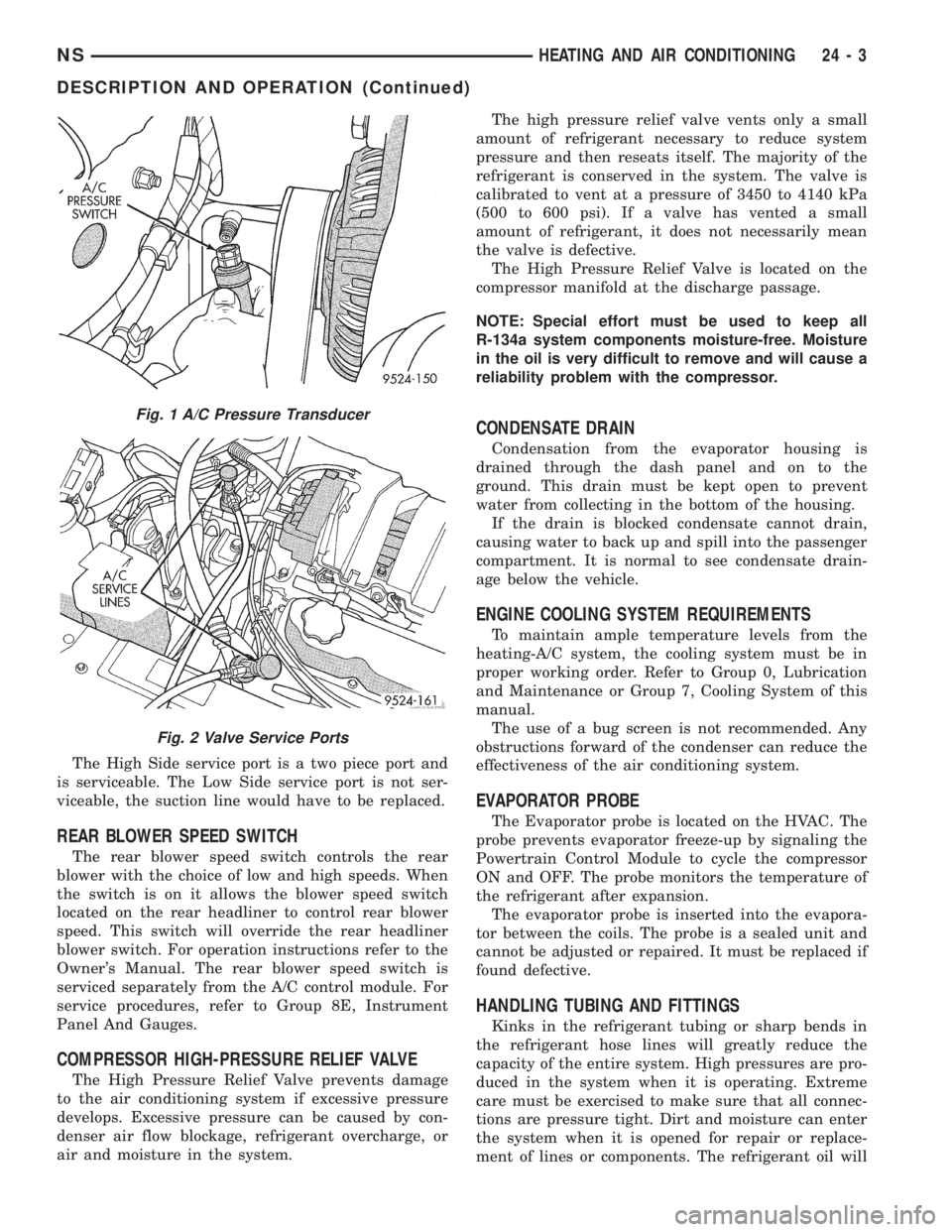
The A/C Pressure Transducer (Fig. 1) monitors the
refrigerant gas pressure on the high side of the sys-
tem. The transducer is located on the liquid line. The
pressure transducer turns off the voltage to the com-
pressor clutch coil when refrigerant gas pressure
drops to levels that could damage the compressor.
The transducer also is used to adjust condenser fan
speeds and will turn off compressor at high refriger-
ant pressures. The pressure transducer is a sealed
factory calibrated unit. It must be replaced if defec-
tive. O-ring replacement is required whenever the
pressure transducer is serviced. Be sure to use the
O-ring specified for the transducer.
A/C SERVICE PORTS
The A/C service port valve cores are located within
the A/C lines (Fig. 2). The High Side (Discharge)
valve service port is located on the liquid line near
the right frame rail. The Low Side (Suction) valve
service port is located on the suction line near the
compressor.
24 - 2 HEATING AND AIR CONDITIONINGNS
Page 1819 of 1938
The High Side service port is a two piece port and
is serviceable. The Low Side service port is not ser-
viceable, the suction line would have to be replaced.
REAR BLOWER SPEED SWITCH
The rear blower speed switch controls the rear
blower with the choice of low and high speeds. When
the switch is on it allows the blower speed switch
located on the rear headliner to control rear blower
speed. This switch will override the rear headliner
blower switch. For operation instructions refer to the
Owner's Manual. The rear blower speed switch is
serviced separately from the A/C control module. For
service procedures, refer to Group 8E, Instrument
Panel And Gauges.
COMPRESSOR HIGH-PRESSURE RELIEF VALVE
The High Pressure Relief Valve prevents damage
to the air conditioning system if excessive pressure
develops. Excessive pressure can be caused by con-
denser air flow blockage, refrigerant overcharge, or
air and moisture in the system.The high pressure relief valve vents only a small
amount of refrigerant necessary to reduce system
pressure and then reseats itself. The majority of the
refrigerant is conserved in the system. The valve is
calibrated to vent at a pressure of 3450 to 4140 kPa
(500 to 600 psi). If a valve has vented a small
amount of refrigerant, it does not necessarily mean
the valve is defective.
The High Pressure Relief Valve is located on the
compressor manifold at the discharge passage.
NOTE: Special effort must be used to keep all
R-134a system components moisture-free. Moisture
in the oil is very difficult to remove and will cause a
reliability problem with the compressor.
CONDENSATE DRAIN
Condensation from the evaporator housing is
drained through the dash panel and on to the
ground. This drain must be kept open to prevent
water from collecting in the bottom of the housing.
If the drain is blocked condensate cannot drain,
causing water to back up and spill into the passenger
compartment. It is normal to see condensate drain-
age below the vehicle.
ENGINE COOLING SYSTEM REQUIREMENTS
To maintain ample temperature levels from the
heating-A/C system, the cooling system must be in
proper working order. Refer to Group 0, Lubrication
and Maintenance or Group 7, Cooling System of this
manual.
The use of a bug screen is not recommended. Any
obstructions forward of the condenser can reduce the
effectiveness of the air conditioning system.
EVAPORATOR PROBE
The Evaporator probe is located on the HVAC. The
probe prevents evaporator freeze-up by signaling the
Powertrain Control Module to cycle the compressor
ON and OFF. The probe monitors the temperature of
the refrigerant after expansion.
The evaporator probe is inserted into the evapora-
tor between the coils. The probe is a sealed unit and
cannot be adjusted or repaired. It must be replaced if
found defective.
HANDLING TUBING AND FITTINGS
Kinks in the refrigerant tubing or sharp bends in
the refrigerant hose lines will greatly reduce the
capacity of the entire system. High pressures are pro-
duced in the system when it is operating. Extreme
care must be exercised to make sure that all connec-
tions are pressure tight. Dirt and moisture can enter
the system when it is opened for repair or replace-
ment of lines or components. The refrigerant oil will
Fig. 1 A/C Pressure Transducer
Fig. 2 Valve Service Ports
NSHEATING AND AIR CONDITIONING 24 - 3
DESCRIPTION AND OPERATION (Continued)
Page 1822 of 1938

CAUTION: The refrigerant oil used in a R-134a A/C
system is unique. Use only oils which were
designed to work with R-134a refrigerant. The oil
designated for this vehicle is ND8 PAG (polyalka-
lene glycol).
SERVICING REFRIGERANT OIL LEVEL
(1) Using a refrigerant recovery machine, remove
refrigerant from the A/C system.
(2) Remove refrigerant lines from A/C compressor.
(3) Remove compressor from vehicle.
(4) From suction port on top of compressor, drain
refrigerant oil from compressor.
(5) Add system capacity minus the capacity of
components that have not been replaced through suc-
tion port on compressor. Refer to the Refrigerant Oil
Capacity Chart.
(6) Install compressor, connect refrigerant lines,
evacuate, and charge refrigerant system.
DIAGNOSIS AND TESTING
ACTUATOR CALIBRATION/DIAGNOSTICS AND
COOLDOWN TEST
GENERAL INFORMATION
If the HVAC control module is replaced, the Cali-
bration Diagnostic and Cooldown tests will need to
be performed. Once this group of tests have success-
fully passed, they can be performed individually. The
engine must be running during the test to provide
hot coolant for the heater, A/C compressor operation
and to assure that the actuators are calibrated cor-
rectly. The HVAC control module is capable of trou-
bleshooting the system in approximately 120 seconds.
If a condition is detected, an error code is displayed.
The error code cannot be erased until the condition is
repaired and the diagnostic test is performed. Check
wire before replacing components, refer to Group 8W,
Wiring Diagrams.CAUTION: Do not remove the actuators from the
Heater-A/C unit assembly with power applied.
Removal should only be done with the Ignition OFF.
The actuators have no mechanical stops to limit the
travel. If the actuator rotates and is not connected
to the unit assembly, it will become out of calibra-
tion.
ACTUATOR CALIBRATION
Mode, Blend and Zone (if equipped) door calibra-
tion compensates for mechanical variations in the
actuators, HVAC control module and its linkages. In-
vehicle calibration can be entered from the control's
front panel. If the REAR WIPE and INTERMIT-
TENT LED's flash simultaneously when Ignition is
cycled ON, the actuators have not been calibrated or
during the previous calibration a failure occurred
(Fig. 6) and (Fig. 7). Diagnostics will always occur
during Calibration Diagnostic and Cooldown test.
REFRIGERANT OIL CAPACITIES
Refrigerant
Oil Capaci-
tiesFront A/C Dual A/C
Component ml oz ml oz
Compressor 150 ml 5.0 oz 220 ml 7.4 oz
Filter-Drier 30 ml 1.0 oz 30 ml 1.0 oz
Condenser 30 ml 1.0 oz 30 ml 1.0 oz
Evaporator 60 ml 2.0 oz 60 ml 2 .0 oz
Rear Evap. N/A N/A 60 ml 2.0 oz
Fig. 6 Radio Bezel and HVAC Control
24 - 6 HEATING AND AIR CONDITIONINGNS
DESCRIPTION AND OPERATION (Continued)