1996 CHRYSLER VOYAGER fuel
[x] Cancel search: fuelPage 1752 of 1938
BODY COMPONENT SERVICE
INDEX
page page
DIAGNOSIS AND TESTING
WATER LEAKS.......................... 23
WIND NOISE........................... 24
SERVICE PROCEDURES
HEAT STAKING......................... 24
REMOVAL AND INSTALLATION
A-PILLAR LOWER EXTENSION TRIM........ 25
A-PILLAR TRIM PANEL................... 25
COWL COVER.......................... 25
COWL TRIM............................ 25
FLOOR CARPET........................ 26
FRONT DOOR APPLIQUE................. 28
FRONT DOOR CHECK STRAP.............. 28
FRONT DOOR FRAME CLOSEOUT MOLDINGS . 29
FRONT DOOR GLASS RUN WEATHER-STRIP . . 30
FRONT DOOR GLASS.................... 29
FRONT DOOR HINGE.................... 30
FRONT DOOR INNER BELT MOLDING....... 31
FRONT DOOR LATCH STRIKER............ 32
FRONT DOOR LATCH.................... 31
FRONT DOOR LOCK CYLINDER............ 32
FRONT DOOR OUTER BELT MOLDING....... 33
FRONT DOOR OUTSIDE HANDLE........... 33
FRONT DOOR REFLECTOR............... 34
FRONT DOOR SILL PLATE................ 34
FRONT DOOR TRIM PANEL................ 34
FRONT DOOR WEATHER-STRIP............ 36
FRONT DOOR WINDOW CRANK............ 36
FRONT DOOR WINDOW REGULATOR....... 36
FRONT DOOR.......................... 27
FRONT SEAT........................... 37
FRONT WHEELHOUSE SPLASH SHIELD..... 37
FUEL FILL DOOR BLOCKER LATCH STRIKER . . 38
FUEL FILL DOOR BLOCKER LATCH......... 38
FUEL FILL DOOR BLOCKER LOCKOUT LINK . . 38
FUEL FILLER HOUSING ± WITH BLOCKER
LATCH .............................. 39
GRILLE............................... 39
HEADLINING........................... 39
HOOD HINGE.......................... 41
HOOD LATCH STRIKER................... 42
HOOD LATCH.......................... 41
HOOD RELEASE CABLE.................. 42
HOOD RELEASE HANDLE................. 42
HOOD................................ 40
JACK STORAGE COVER.................. 43
LEFT D-PILLAR TRIM PANEL............... 43
LEFT QUARTER TRIM PANEL.............. 44
LIFTGATE CHMSL ACCESS PANEL.......... 47
LIFTGATE HINGE........................ 47LIFTGATE LATCH STRIKER................ 47
LIFTGATE LATCH........................ 47
LIFTGATE LOCK CYLINDER............... 48
LIFTGATE OUTSIDE HANDLE.............. 48
LIFTGATE PROP ASSEMBLY............... 49
LIFTGATE SILL PLATE.................... 49
LIFTGATE STABILIZER WEDGE STRIKER..... 49
LIFTGATE STABILIZER WEDGE............. 49
LIFTGATE TRIM PANEL................... 50
LIFTGATE UPPER FRAME MOLDING........ 50
LIFTGATE UPPER FRAME SIDE MOLDINGS . . . 51
LIFTGATE............................. 46
LOWER B-PILLAR TRIM COVER............ 51
LUGGAGE RACK CROSSBAR.............. 51
LUGGAGE RACK RISER COVER............ 52
LUGGAGE RACK SIDE RAIL............... 52
OVERHEAD GRAB-HANDLES.............. 52
QUARTER GLASS....................... 52
QUARTER TRIM BOLSTER................ 53
RADIATOR CLOSURE PANEL CROSSMEMBER . 53
RAIL LAMP MODULE..................... 54
REAR HEADER TRIM..................... 55
REAR HVAC LOUVER AND BEZEL.......... 55
RIGHT D-PILLAR TRIM PANEL.............. 55
RIGHT QUARTER TRIM PANEL............. 56
ROOF APERTURE (RAP) MOLDING.......... 57
SEAT BELT BUCKLE FIRST REAR QUAD
BUCKET............................. 58
SEAT BELT BUCKLE FIRST REAR ± TWO
PASSENGER BENCH................... 58
SEAT BELT BUCKLE SECOND REAR ± THREE
PASSENGER BENCH................... 59
SEAT BELT BUCKLE ± FRONT INBOARD..... 57
SEAT BELT FIRST REAR ANCHOR BRACKET ±
LWB ................................ 59
SEAT BELT FIRST REAR OUTBOARD ± LWB
FOUR DOOR.......................... 60
SEAT BELT FIRST REAR OUTBOARD ± SWB
FOUR DOOR.......................... 60
SEAT BELT LEFT FIRST REAR OUTBOARD ±
LWB THREE DOOR..................... 61
SEAT BELT LEFT FIRST REAR OUTBOARD ±
SWB THREE DOOR.................... 61
SEAT BELT SECOND REAR OUTBOARD ±
SWB ................................ 61
SEAT BELT SECOND RIGHT REAR OUTBOARD
±LWB ............................... 62
SEAT BELT ± OUTBOARD FRONT........... 59
SECOND RIGHT REAR OUTBOARD SEAT BELT
± LWB W/REAR HVAC................... 62
23 - 22 BODYNS
Page 1757 of 1938
CAUTION: Ensure that the correct fasteners are
installed in the proper locations. Damage to the fuel
tank may result.
(5) Install floor escutcheons.
(6) Install Quarter trim panels.
(7) Install D-pillar trim covers.
(8) Install lower B-pillar trim covers.
(9) Install rear door sill plate.
(10) Install sliding door sill plates.
(11) Install front cowl panels and sill plates.
(12) Install second rear seat.
(13) Install first rear seat.
(14) Install front center console.
(15) Install front seats.
FRONT DOOR
CAUTION: If the hinge pin must be removed from
the hinge, do not reuse the original pin. The struc-
tural integrity of the hinge would be reduced. Verify
availability prior to proceeding if hinge pins are to
be removed.
NOTE: The retaining clips used on the door hinge
pins are not to be re-used. Verify availability prior to
proceeding if clips are to be removed.
REMOVAL
(1) Open front door.
(2) Remove front wheelhouse splash shield.(3) Disengage clips holding door harness wire con-
nector to inner fender brace.
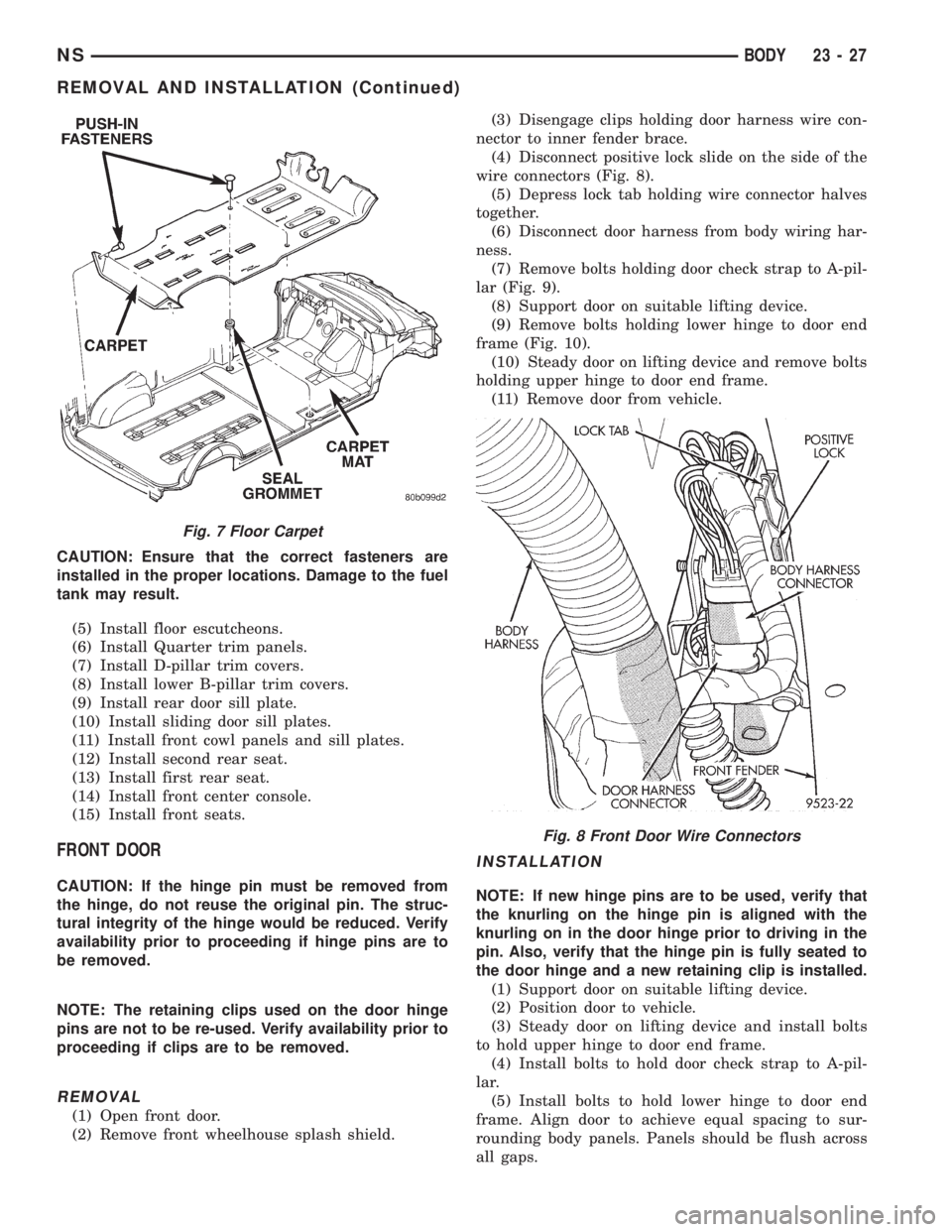
(4) Disconnect positive lock slide on the side of the
wire connectors (Fig. 8).
(5) Depress lock tab holding wire connector halves
together.
(6) Disconnect door harness from body wiring har-
ness.
(7) Remove bolts holding door check strap to A-pil-
lar (Fig. 9).
(8) Support door on suitable lifting device.
(9) Remove bolts holding lower hinge to door end
frame (Fig. 10).
(10) Steady door on lifting device and remove bolts
holding upper hinge to door end frame.
(11) Remove door from vehicle.
INSTALLATION
NOTE: If new hinge pins are to be used, verify that
the knurling on the hinge pin is aligned with the
knurling on in the door hinge prior to driving in the
pin. Also, verify that the hinge pin is fully seated to
the door hinge and a new retaining clip is installed.
(1) Support door on suitable lifting device.
(2) Position door to vehicle.
(3) Steady door on lifting device and install bolts
to hold upper hinge to door end frame.
(4) Install bolts to hold door check strap to A-pil-
lar.
(5) Install bolts to hold lower hinge to door end
frame. Align door to achieve equal spacing to sur-
rounding body panels. Panels should be flush across
all gaps.
Fig. 7 Floor Carpet
Fig. 8 Front Door Wire Connectors
NSBODY 23 - 27
REMOVAL AND INSTALLATION (Continued)
Page 1768 of 1938
FUEL FILL DOOR BLOCKER LATCH
REMOVAL
(1) Remove left quarter trim panel.
(2) Remove water shield patch covering access hole
in C-pillar.
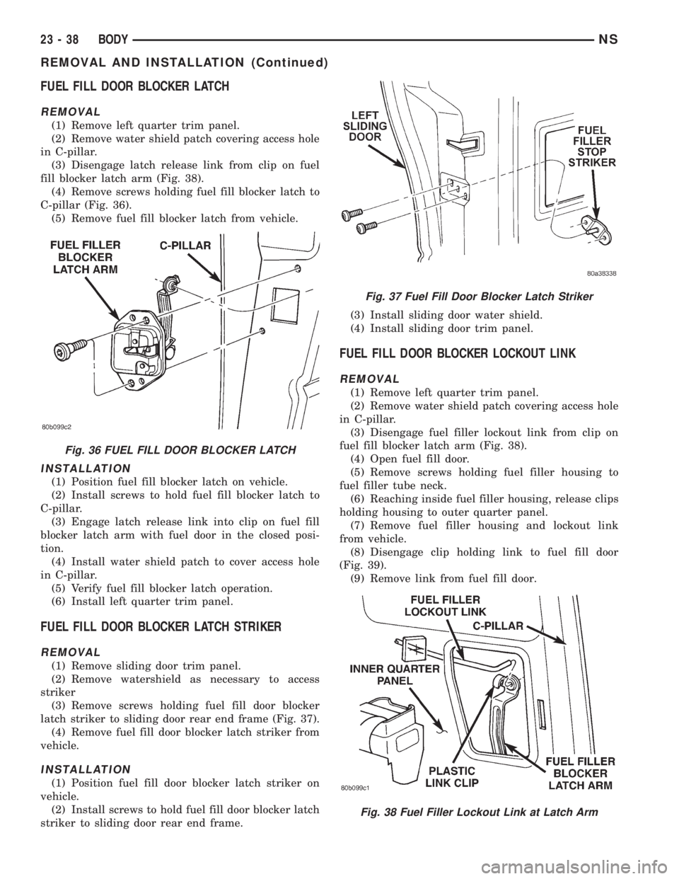
(3) Disengage latch release link from clip on fuel
fill blocker latch arm (Fig. 38).
(4) Remove screws holding fuel fill blocker latch to
C-pillar (Fig. 36).
(5) Remove fuel fill blocker latch from vehicle.
INSTALLATION
(1) Position fuel fill blocker latch on vehicle.
(2) Install screws to hold fuel fill blocker latch to
C-pillar.
(3) Engage latch release link into clip on fuel fill
blocker latch arm with fuel door in the closed posi-
tion.
(4) Install water shield patch to cover access hole
in C-pillar.
(5) Verify fuel fill blocker latch operation.
(6) Install left quarter trim panel.
FUEL FILL DOOR BLOCKER LATCH STRIKER
REMOVAL
(1) Remove sliding door trim panel.
(2) Remove watershield as necessary to access
striker
(3) Remove screws holding fuel fill door blocker
latch striker to sliding door rear end frame (Fig. 37).
(4) Remove fuel fill door blocker latch striker from
vehicle.
INSTALLATION
(1) Position fuel fill door blocker latch striker on
vehicle.
(2) Install screws to hold fuel fill door blocker latch
striker to sliding door rear end frame.(3) Install sliding door water shield.
(4) Install sliding door trim panel.
FUEL FILL DOOR BLOCKER LOCKOUT LINK
REMOVAL
(1) Remove left quarter trim panel.
(2) Remove water shield patch covering access hole
in C-pillar.
(3) Disengage fuel filler lockout link from clip on
fuel fill blocker latch arm (Fig. 38).
(4) Open fuel fill door.
(5) Remove screws holding fuel filler housing to
fuel filler tube neck.
(6) Reaching inside fuel filler housing, release clips
holding housing to outer quarter panel.
(7) Remove fuel filler housing and lockout link
from vehicle.
(8) Disengage clip holding link to fuel fill door
(Fig. 39).
(9) Remove link from fuel fill door.
Fig. 36 FUEL FILL DOOR BLOCKER LATCH
Fig. 37 Fuel Fill Door Blocker Latch Striker
Fig. 38 Fuel Filler Lockout Link at Latch Arm
23 - 38 BODYNS
REMOVAL AND INSTALLATION (Continued)
Page 1769 of 1938
INSTALLATION
(1) Insert link into clip on fuel fill door.
(2) Engage clip to hold link to fuel fill door.
(3) Insert lockout link through grommet in panel
between inner and outer quarter panel.
(4) Close fuel fill door.
(5) Install fuel filler housing to outer quarter
panel.
(6) Verify that all clips on fuel filler housing are
fully engaged to outer quarter panel.
(7) Engage fuel filler lockout link into clip on fuel
fill blocker latch arm.
(8) Install water shield patch covering access hole
in C-pillar.
(9) Install left quarter trim panel.
FUEL FILLER HOUSING ± WITH BLOCKER LATCH
REMOVAL
(1) Remove left quarter trim panel.
(2) Remove water shield patch covering access hole
in C-pillar.
(3) Disengage latch release link from clip on fuel
fill blocker latch arm (Fig. 38).
(4) Open fuel fill door.
(5) Remove screws holding fuel fill neck to fuel
filler housing.
(6) Position fuel fill neck out of the way.
(7) Reaching inside fuel filler housing, release clips
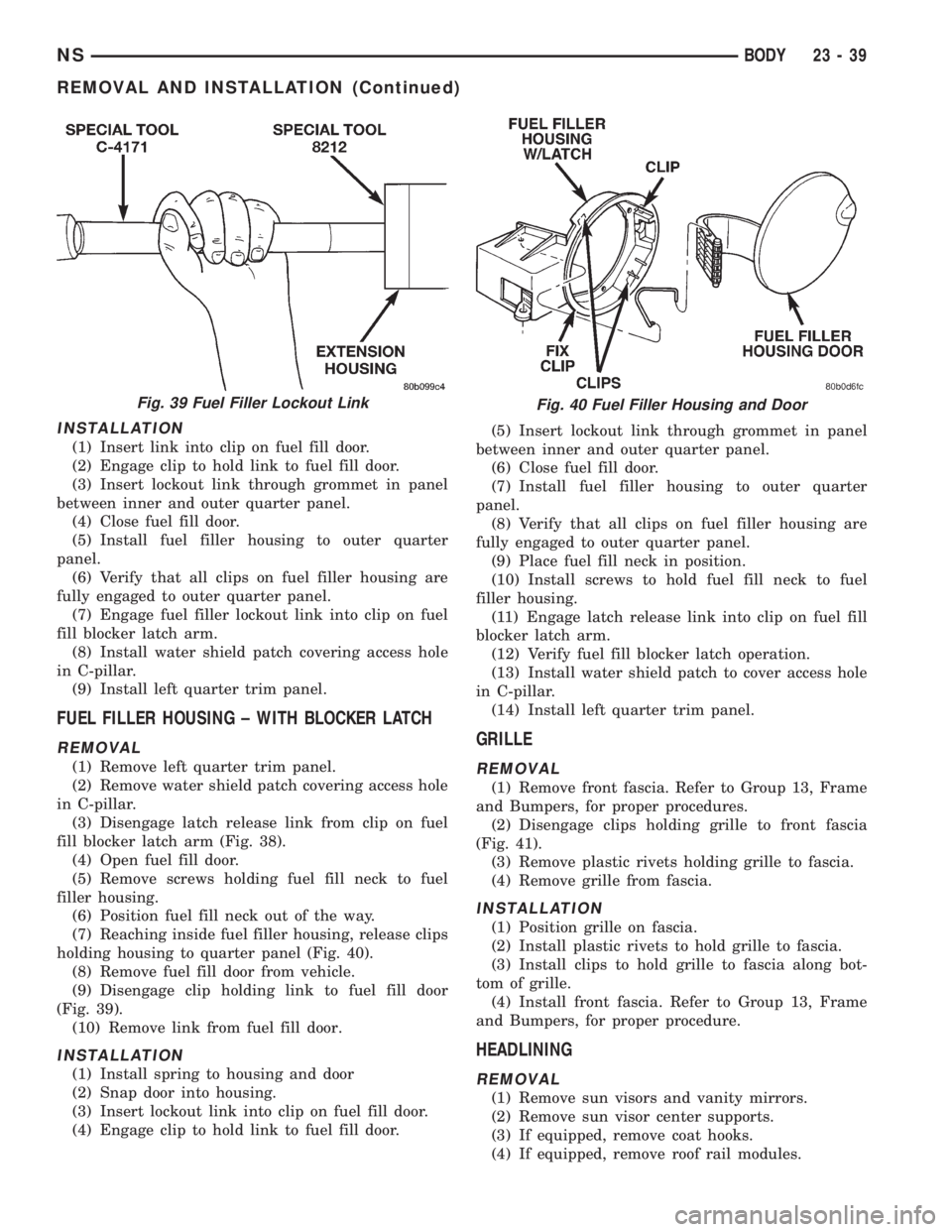
holding housing to quarter panel (Fig. 40).
(8) Remove fuel fill door from vehicle.
(9) Disengage clip holding link to fuel fill door
(Fig. 39).
(10) Remove link from fuel fill door.
INSTALLATION
(1) Install spring to housing and door
(2) Snap door into housing.
(3) Insert lockout link into clip on fuel fill door.
(4) Engage clip to hold link to fuel fill door.(5) Insert lockout link through grommet in panel
between inner and outer quarter panel.
(6) Close fuel fill door.
(7) Install fuel filler housing to outer quarter
panel.
(8) Verify that all clips on fuel filler housing are
fully engaged to outer quarter panel.
(9) Place fuel fill neck in position.
(10) Install screws to hold fuel fill neck to fuel
filler housing.
(11) Engage latch release link into clip on fuel fill
blocker latch arm.
(12) Verify fuel fill blocker latch operation.
(13) Install water shield patch to cover access hole
in C-pillar.
(14) Install left quarter trim panel.
GRILLE
REMOVAL
(1) Remove front fascia. Refer to Group 13, Frame
and Bumpers, for proper procedures.
(2) Disengage clips holding grille to front fascia
(Fig. 41).
(3) Remove plastic rivets holding grille to fascia.
(4) Remove grille from fascia.
INSTALLATION
(1) Position grille on fascia.
(2) Install plastic rivets to hold grille to fascia.
(3) Install clips to hold grille to fascia along bot-
tom of grille.
(4) Install front fascia. Refer to Group 13, Frame
and Bumpers, for proper procedure.
HEADLINING
REMOVAL
(1) Remove sun visors and vanity mirrors.
(2) Remove sun visor center supports.
(3) If equipped, remove coat hooks.
(4) If equipped, remove roof rail modules.
Fig. 39 Fuel Filler Lockout LinkFig. 40 Fuel Filler Housing and Door
NSBODY 23 - 39
REMOVAL AND INSTALLATION (Continued)
Page 1810 of 1938
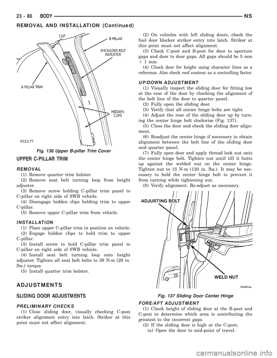
UPPER C-PILLAR TRIM
REMOVAL
(1) Remove quarter trim bolster.
(2) Remove seat belt turning loop from height
adjuster.
(3) Remove screw holding C-pillar trim panel to
C-pillar on right side of SWB vehicle.
(4) Disengage hidden clips holding trim to upper
C-pillar.
(5) Remove upper C-pillar trim from vehicle.
INSTALLATION
(1) Place upper C-pillar trim in position on vehicle.
(2) Engage hidden clips to hold trim to upper
C-pillar.
(3) Install screw to hold C-pillar trim panel to
C-pillar on right side of SWB vehicle.
(4) Install seat belt turning loop onto height
adjuster. Tighten all seat belt bolts to 39 N´m (29 in.
lbs.) torque.
(5) Install quarter trim bolster.
ADJUSTMENTS
SLIDING DOOR ADJUSTMENTS
PRELIMINARY CHECKS
(1) Close sliding door, visually checking C-post
striker alignment entry into latch. Striker at this
point must not affect alignment.(2) On vehicles with left sliding doors, check the
fuel door blocker striker entry into latch. Striker at
this point must not affect alignment.
(3) Check C-post and B-post for door to aperture
gaps and door to door gaps. All gaps should be 5 mm
61 mm.
(4) C
heck door for height using character lines as a
reference. Also check roof contour as a controlling factor.
UP/DOWN ADJUSTMENT
(1) Visually inspect the sliding door for fitting low
at the rear of the door by checking the alignment of
the belt line of the door to quarter panel.
(2) Fully open the sliding door.
(3) Verify that all center hinge bolts are tight.
(4) Adjust the rear of the sliding door up by turn-
ing the center hinge bolt clockwise (Fig. 137).
(5) Close the door and check the sliding door align-
ment.
(6) Readjust the center hinge if necessary to obtain
alignment between the belt line of the sliding door
and quarter panel.
(7) Fully open door and apply thread lock nut onto
the center hinge bolt. Tighten nut until till it butts
up against the welded nut on the center hinge.
Tighten nut to 15 N´m (130 in. lbs.). It may be nec-
essary to hold the center hinge bolt to prevent it
from turning while tightening nut.
(8) Verify alignment. Re-adjust as necessary.
FORE/AFT ADJUSTMENT
(1) Check height of sliding door at the B-post and
C-post to determine which area is contributing the
greatest to the incorrect gaps.
(2) If the sliding door is high at the C-post;
(a) Open the door to mid-point of travel.
Fig. 136 Upper B-pillar Trim Cover
Fig. 137 Sliding Door Center Hinge
23 - 80 BODYNS
REMOVAL AND INSTALLATION (Continued)
Page 1905 of 1938
EMISSION CONTROL SYSTEMS
CONTENTS
page page
EVAPORATIVE EMISSION CONTROLS........ 13
EXHAUST GAS RECIRCULATION (EGR)
SYSTEM.............................. 18ON-BOARD DIAGNOSTICS.................. 1
ON-BOARD DIAGNOSTICS
INDEX
page page
GENERAL INFORMATION
SYSTEM DESCRIPTION................... 1
DESCRIPTION AND OPERATION
CIRCUIT ACTUATION TEST MODE........... 3
COMPONENT MONITORS................. 10
DIAGNOSTIC TROUBLE CODES............. 3
HIGH AND LOW LIMITS................... 11LOAD VALUE........................... 12
MALFUNCTION INDICATOR LAMP (MIL)....... 1
MONITORED SYSTEMS.................... 8
NON-MONITORED CIRCUITS............... 11
STATE DISPLAY TEST MODE............... 2
TRIP DEFINITION........................ 10
GENERAL INFORMATION
SYSTEM DESCRIPTION
The Powertrain Control Module (PCM) monitors
many different circuits in the fuel injection, ignition,
emission and engine systems. If the PCM senses a
problem with a monitored circuit often enough to
indicate an actual problem, it stores a Diagnostic
Trouble Code (DTC) in the PCM's memory. If the
code applies to a non-emissions related component or
system, and the problem is repaired or ceases to
exist, the PCM cancels the code after 40 warmup
cycles. Diagnostic trouble codes that affect vehicle
emissions illuminate the Malfunction Indicator Lamp
(MIL). Refer to Malfunction Indicator Lamp in this
section.
Certain criteria must be met before the PCM
stores a DTC in memory. The criteria may be a spe-
cific range of engine RPM, engine temperature,
and/or input voltage to the PCM.
The PCM might not store a DTC for a monitored
circuit even though a malfunction has occurred. This
may happen because one of the DTC criteria for the
circuit has not been met.For example, assume the
diagnostic trouble code criteria requires the PCM to
monitor the circuit only when the engine operates
between 750 and 2000 RPM. Suppose the sensor'soutput circuit shorts to ground when engine operates
above 2400 RPM (resulting in 0 volt input to the
PCM). Because the condition happens at an engine
speed above the maximum threshold (2000 rpm), the
PCM will not store a DTC.
There are several operating conditions for which
the PCM monitors and sets DTC's. Refer to Moni-
tored Systems, Components, and Non-Monitored Cir-
cuits in this section.
NOTE: Various diagnostic procedures may actually
cause a diagnostic monitor to set a DTC. For
instance, pulling a spark plug wire to perform a
spark test may set the misfire code. When a repair
is completed and verified, use the DRB scan tool to
erase all DTC's and extinguish the MIL.
Technicians can display stored DTC's by using the
DRB scan tool. Refer to Diagnostic Trouble Codes in
this section. For DTC information, refer to charts in
this section.
DESCRIPTION AND OPERATION
MALFUNCTION INDICATOR LAMP (MIL)
As a functional test, the Malfunction Indicator
Lamp (MIL) illuminates at key-on before engine
NSEMISSION CONTROL SYSTEMS 25 - 1
Page 1906 of 1938
cranking. Whenever the Powertrain Control Module
(PCM) sets a Diagnostic Trouble Code (DTC) that
affects vehicle emissions, it illuminates the MIL. If a
problem is detected, the PCM sends a message over
the CCD Bus to the instrument cluster to illuminate
the lamp. The PCM illuminates the MIL only for
DTC's that affect vehicle emissions. The MIL stays
on continuously when the PCM has entered a
Limp-In mode or identified a failed emission compo-
nent or system. The MIL remains on until the DTC
is erased. Refer to the Diagnostic Trouble Code
charts in this group for emission related codes.
Also, the MIL either flashes or illuminates contin-
uously when the PCM detects active engine misfire.
Refer to Misfire Monitoring in this section.
Additionally, the PCM may reset (turn off) the MIL
when one of the following occur:
²PCM does not detect the malfunction for 3 con-
secutive trips (except misfire and fuel system moni-
tors).
²PCM does not detect a malfunction while per-
forming three successive engine misfire or fuel sys-
tem tests. The PCM performs these tests while the
engine is operating within6375 RPM of and within
10 % of the load of the operating condition at which
the malfunction was first detected.
STATE DISPLAY TEST MODE
The switch inputs to the Powertrain Control Mod-
ule (PCM) have two recognized states; HIGH and
LOW. For this reason, the PCM cannot recognize the
difference between a selected switch position versus
an open circuit, a short circuit, or a defective switch.
If the State Display screen shows the change from
HIGH to LOW or LOW to HIGH, assume the entire
switch circuit to the PCM functions properly. From
the state display screen, access either State Display
Inputs and Outputs or State Display Sensors.
STATE DISPLAY INPUTS AND OUTPUTS
Connect the DRB scan tool to the data link connec-
tor and access the State Display screen. Then access
Inputs and Outputs. The following list contains the
PCM system functions accessible through the Inputs
and Outputs screen.
Park/Neutral Switch
Speed Control Resume
Brake Switch
Speed Control On/Off
Speed Control Set
S/C Vent Solenoid
Actual S/C Vent Sol.
S/C Vacuum Solenoid
Actual S/C Vacuum Sol.
S/C Cancel
S/C Last Cutout
S/C Working Status
S/C Denied Status
A/C Clutch Relay
Actual A/C Clutch Relay
EGR Solenoid
Actual EGR Sol.
Automatic Shutdown Relay
Actual Automatic Shutdown Relay
Automatic Shutdown Relay Sense
Radiator Fan Control Module
Actual Radiator Fan Control Module
Duty Cycle EVAP Purge Solenoid
Actual EVAP Purge Sol.
Torque Converter Clutch Solenoid
Power Steering Switch
Closed Loop State
Current CMP Edge
Current CKP State
Current Sync State
Fuel Pump Relay
Actual Fuel Pump Relay
Ignition Sense (A21)
Malfunction Lamp
Limp-in Reason
STATE DISPLAY SENSORS
Connect the DRB scan tool to the vehicle and
access the State Display screen. Then access Sensor
Display. The following list contains the PCM system
functions accessible through the Sensor Display
screen.
Battery Temperature
Engine Coolant Temperature
Engine Coolant Temp Sensor
Throttle Position Volts
Minimum Throttle
Knock Sensor Volts
Battery Voltage
MAP Sensor Reading
Idle Air Control Motor Position
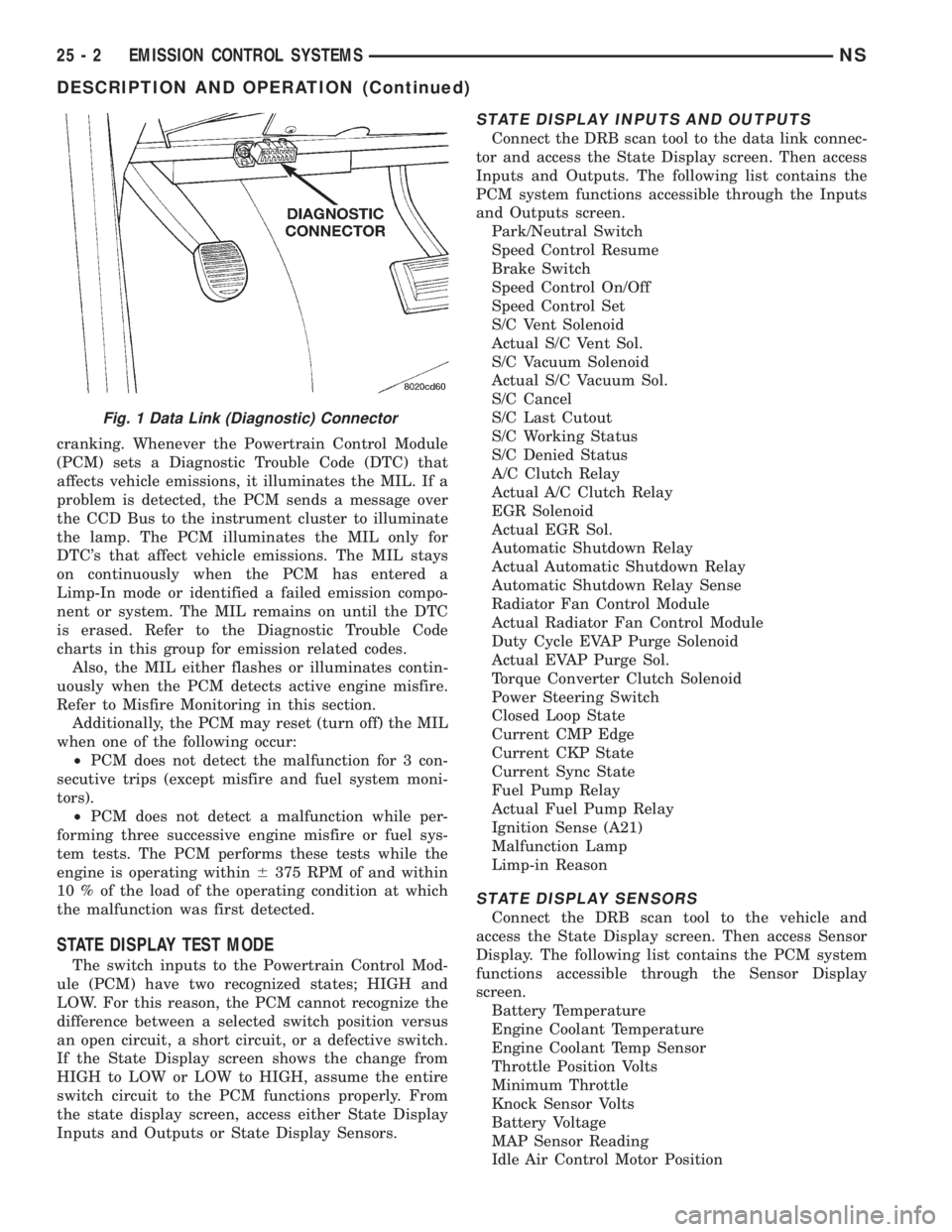
Fig. 1 Data Link (Diagnostic) Connector
25 - 2 EMISSION CONTROL SYSTEMSNS
DESCRIPTION AND OPERATION (Continued)
Page 1907 of 1938
Adaptive Fuel Factor
Barometric Pressure
Engine Speed
Module Spark Advance
Speed Control Target
Intake Air Temp Degrees
Intake Air Temp Volts
Charging System Goal
Theft Alarm Status
Map Sensor Voltage
Vehicle Speed
Throttle Opening (percentage)
TPS Calculated
Cam Timing Position
Target Idle
Time From Start To Run
Run Time At Stall
Injector Pulse-width
Upstream O2S Volts
Downstream O2S Volts
Closed Loop Timer
Short Term Adaptive
Current Adaptive Cell
Adaptive Memory Cell 0
Adaptive Memory Cell 1
Adaptive Memory Cell 2
Adaptive Memory Cell 3
Adaptive Memory Cell 4
Adaptive Memory Cell 5
Adaptive Memory Cell 6
Adaptive Memory Cell 7
Adaptive Memory Cell 8
Adaptive Memory Cell 9
Adaptive Memory Cell 10
Adaptive Memory Cell 11
Adaptive Memory Cell 12
Adaptive Memory Cell 13
Adaptive Memory Cell 14
Adaptive Memory Cell 15
Purge Free Idle Cell
Purge Free Cell 2 (corresponds to memory cell 2)
Purge Free Cell 3 (corresponds to memory cell 5)
Target IAC Steps
Retard Cylinder (1)
Retard Cylinder (2)
Retard Cylinder (3)
Retard Cylinder (4)
Retard Cylinder (5)
Retard Cylinder (6)CIRCUIT ACTUATION TEST MODE
The Circuit Actuation Test Mode checks for proper
operation of output circuits or devices the Powertrain
Control Module (PCM) may not internally recognize.
The PCM attempts to activate these outputs and
allow an observer to verify proper operation. Most of
the tests provide an audible or visual indication of
device operation (click of relay contacts, fuel spray,
etc.). Except for intermittent conditions, if a device
functions properly during testing, assume the device,
its associated wiring, and driver circuit work cor-
rectly.
DIAGNOSTIC TROUBLE CODES
A Diagnostic Trouble Code (DTC) indicates the
PCM has recognized an abnormal condition in the
system.
The preferred and most accurate method of retriev-
ing a DTC is by using the DRB scan tool. The scan
tool supplies detailed diagnostic information which
can be used to more accurately diagnose causes for a
DTC.
Remember that DTC's are the results of a sys-
tem or circuit failure, but do not directly iden-
tify the failed component or components.
NOTE: For a list of DTC's, refer to the charts in this
section.
BULB CHECK
Each time the ignition key is turned to the ON
position, the malfunction indicator (check engine)
lamp on the instrument panel should illuminate for
approximately 2 seconds then go out. This is done for
a bulb check.
OBTAINING DTC'S USING DRB SCAN TOOL
(1) Connect the DRB scan tool to the data link
(diagnostic) connector. This connector is located in
the passenger compartment; at the lower edge of
instrument panel; near the steering column.
(2) Turn the ignition switch on and access the
ªRead Faultº screen.
(3) Record all the DTC's and ªfreeze frameº infor-
mation shown on the DRB scan tool.
(4) To erase DTC's, use the ªErase Trouble Codeº
data screen on the DRB scan tool.Do not erase any
DTC's until problems have been investigated
and repairs have been performed.
NSEMISSION CONTROL SYSTEMS 25 - 3
DESCRIPTION AND OPERATION (Continued)