1996 CHRYSLER VOYAGER fuel
[x] Cancel search: fuelPage 1421 of 1938
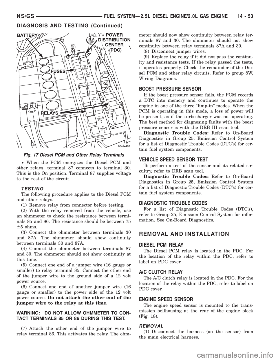
²When the PCM energizes the Diesel PCM and
other relays, terminal 87 connects to terminal 30.
This is the On position. Terminal 87 supplies voltage
to the rest of the circuit.
TESTING
The following procedure applies to the Diesel PCM
and other relays.
(1) Remove relay from connector before testing.
(2) With the relay removed from the vehicle, use
an ohmmeter to check the resistance between termi-
nals 85 and 86. The resistance should be between 75
65 ohms.
(3) Connect the ohmmeter between terminals 30
and 87A. The ohmmeter should show continuity
between terminals 30 and 87A.
(4) Connect the ohmmeter between terminals 87
and 30. The ohmmeter should not show continuity at
this time.
(5) Connect one end of a jumper wire (16 gauge or
smaller) to relay terminal 85. Connect the other end
of the jumper wire to the ground side of a 12 volt
power source.
(6) Connect one end of another jumper wire (16
gauge or smaller) to the power side of the 12 volt
power source.Do not attach the other end of the
jumper wire to the relay at this time.
WARNING: DO NOT ALLOW OHMMETER TO CON-
TACT TERMINALS 85 OR 86 DURING THIS TEST.
(7) Attach the other end of the jumper wire to
relay terminal 86. This activates the relay. The ohm-meter should now show continuity between relay ter-
minals 87 and 30. The ohmmeter should not show
continuity between relay terminals 87A and 30.
(8) Disconnect jumper wires.
(9) Replace the relay if it did not pass the continu-
ity and resistance tests. If the relay passed the tests,
it operates properly. Check the remainder of the Die-
sel PCM and other relay circuits. Refer to group 8W,
Wiring Diagrams.
BOOST PRESSURE SENSOR
If the boost pressure sensor fails, the PCM records
a DTC into memory and continues to operate the
engine in one of the three ªlimp-inº modes. When the
PCM is operating in this mode, a loss of power will
be present, as if the turbocharger was not operating.
The best method for diagnosing faults with the boost
pressure sensor is with the DRB III scan tool.
Diagnostic Trouble Codes:Refer to On-Board
Diagnostics in Group 25, Emission Control System
for a list of Diagnostic Trouble Codes (DTC's) for cer-
tain fuel system components.
VEHICLE SPEED SENSOR TEST
To perform a test of the sensor and its related cir-
cuitry, refer to DRB scan tool.
Diagnostic Trouble Codes:Refer to On-Board
Diagnostics in Group 25, Emission Control System
for a list of Diagnostic Trouble Codes (DTC's) for cer-
tain fuel system components.
DIAGNOSTIC TROUBLE CODES
For a list of Diagnostic Trouble Codes (DTC's),
refer to Group 25, Emission Control System for infor-
mation. See On-Board Diagnostics.
REMOVAL AND INSTALLATION
DIESEL PCM RELAY
The Diesel PCM relay is located in the PDC. For
the location of the relay within the PDC, refer to
label on PDC cover.
A/C CLUTCH RELAY
The A/C clutch relay is located in the PDC. For the
location of the relay within the PDC, refer to label on
PDC cover.
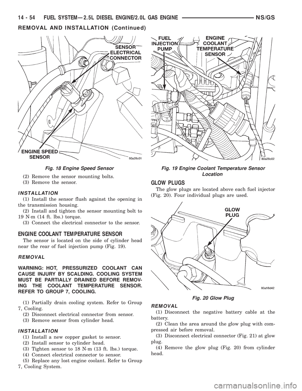
ENGINE SPEED SENSOR
The engine speed sensor is mounted to the trans-
mission bellhousing at the rear of the engine block
(Fig. 18).
REMOVAL
(1) Disconnect the harness (on the sensor) from
the main electrical harness.
Fig. 17 Diesel PCM and Other Relay Terminals
NS/GSFUEL SYSTEMÐ2.5L DIESEL ENGINE/2.0L GAS ENGINE 14 - 53
DIAGNOSIS AND TESTING (Continued)
Page 1422 of 1938
(2) Remove the sensor mounting bolts.
(3) Remove the sensor.
INSTALLATION
(1) Install the sensor flush against the opening in
the transmission housing.
(2) Install and tighten the sensor mounting bolt to
19 N´m (14 ft. lbs.) torque.
(3) Connect the electrical connector to the sensor.
ENGINE COOLANT TEMPERATURE SENSOR
The sensor is located on the side of cylinder head
near the rear of fuel injection pump (Fig. 19).
REMOVAL
WARNING: HOT, PRESSURIZED COOLANT CAN
CAUSE INJURY BY SCALDING. COOLING SYSTEM
MUST BE PARTIALLY DRAINED BEFORE REMOV-
ING THE COOLANT TEMPERATURE SENSOR.
REFER TO GROUP 7, COOLING.
(1) Partially drain cooling system. Refer to Group
7, Cooling.
(2) Disconnect electrical connector from sensor.
(3) Remove sensor from cylinder head.
INSTALLATION
(1) Install a new copper gasket to sensor.
(2) Install sensor to cylinder head.
(3) Tighten sensor to 18 N´m (13 ft. lbs.) torque.
(4) Connect electrical connector to sensor.
(5) Replace any lost engine coolant. Refer to Group
7, Cooling System.
GLOW PLUGS
The glow plugs are located above each fuel injector
(Fig. 20). Four individual plugs are used.
REMOVAL
(1) Disconnect the negative battery cable at the
battery.
(2) Clean the area around the glow plug with com-
pressed air before removal.
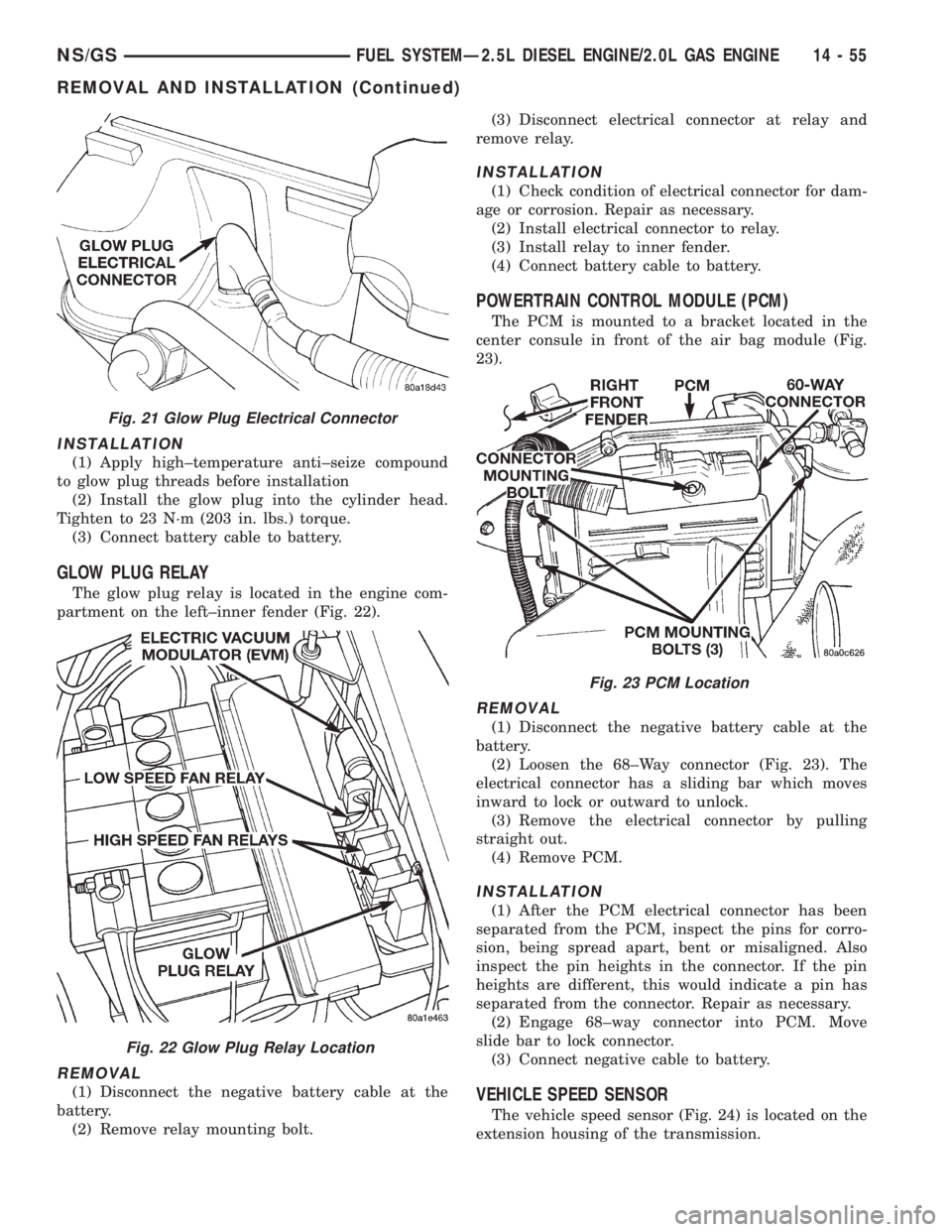
(3) Disconnect electrical connector (Fig. 21) at glow
plug.
(4) Remove the glow plug (Fig. 20) from cylinder
head.
Fig. 18 Engine Speed SensorFig. 19 Engine Coolant Temperature Sensor
Location
Fig. 20 Glow Plug
14 - 54 FUEL SYSTEMÐ2.5L DIESEL ENGINE/2.0L GAS ENGINENS/GS
REMOVAL AND INSTALLATION (Continued)
Page 1423 of 1938
INSTALLATION
(1) Apply high±temperature anti±seize compound
to glow plug threads before installation
(2) Install the glow plug into the cylinder head.
Tighten to 23 N´m (203 in. lbs.) torque.
(3) Connect battery cable to battery.
GLOW PLUG RELAY
The glow plug relay is located in the engine com-
partment on the left±inner fender (Fig. 22).
REMOVAL
(1) Disconnect the negative battery cable at the
battery.
(2) Remove relay mounting bolt.(3) Disconnect electrical connector at relay and
remove relay.
INSTALLATION
(1) Check condition of electrical connector for dam-
age or corrosion. Repair as necessary.
(2) Install electrical connector to relay.
(3) Install relay to inner fender.
(4) Connect battery cable to battery.
POWERTRAIN CONTROL MODULE (PCM)
The PCM is mounted to a bracket located in the
center consule in front of the air bag module (Fig.
23).
REMOVAL
(1) Disconnect the negative battery cable at the
battery.
(2) Loosen the 68±Way connector (Fig. 23). The
electrical connector has a sliding bar which moves
inward to lock or outward to unlock.
(3) Remove the electrical connector by pulling
straight out.
(4) Remove PCM.
INSTALLATION
(1) After the PCM electrical connector has been
separated from the PCM, inspect the pins for corro-
sion, being spread apart, bent or misaligned. Also
inspect the pin heights in the connector. If the pin
heights are different, this would indicate a pin has
separated from the connector. Repair as necessary.
(2) Engage 68±way connector into PCM. Move
slide bar to lock connector.
(3) Connect negative cable to battery.
VEHICLE SPEED SENSOR
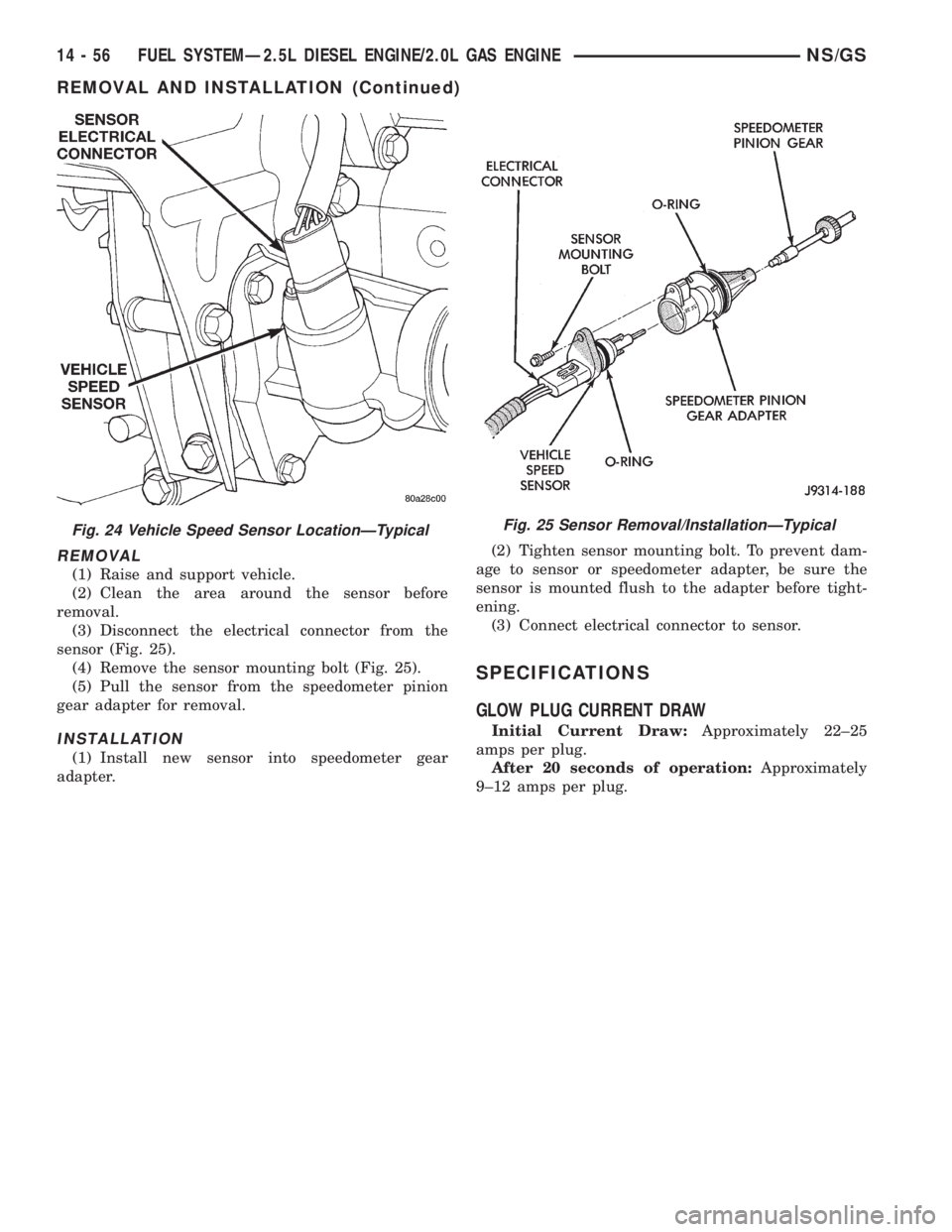
The vehicle speed sensor (Fig. 24) is located on the
extension housing of the transmission.
Fig. 21 Glow Plug Electrical Connector
Fig. 22 Glow Plug Relay Location
Fig. 23 PCM Location
NS/GSFUEL SYSTEMÐ2.5L DIESEL ENGINE/2.0L GAS ENGINE 14 - 55
REMOVAL AND INSTALLATION (Continued)
Page 1424 of 1938
REMOVAL
(1) Raise and support vehicle.
(2) Clean the area around the sensor before
removal.
(3) Disconnect the electrical connector from the
sensor (Fig. 25).
(4) Remove the sensor mounting bolt (Fig. 25).
(5) Pull the sensor from the speedometer pinion
gear adapter for removal.
INSTALLATION
(1) Install new sensor into speedometer gear
adapter.(2) Tighten sensor mounting bolt. To prevent dam-
age to sensor or speedometer adapter, be sure the
sensor is mounted flush to the adapter before tight-
ening.
(3) Connect electrical connector to sensor.
SPECIFICATIONS
GLOW PLUG CURRENT DRAW
Initial Current Draw:Approximately 22±25
amps per plug.
After 20 seconds of operation:Approximately
9±12 amps per plug.
Fig. 25 Sensor Removal/InstallationÐTypicalFig. 24 Vehicle Speed Sensor LocationÐTypical
14 - 56 FUEL SYSTEMÐ2.5L DIESEL ENGINE/2.0L GAS ENGINENS/GS
REMOVAL AND INSTALLATION (Continued)
Page 1425 of 1938
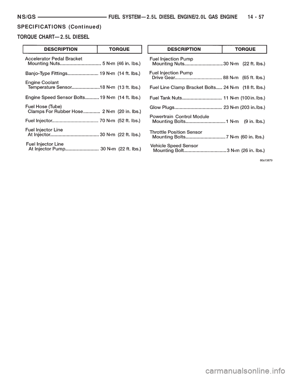
TORQUE CHARTÐ2.5L DIESEL
NS/GSFUEL SYSTEMÐ2.5L DIESEL ENGINE/2.0L GAS ENGINE 14 - 57
SPECIFICATIONS (Continued)
Page 1474 of 1938
(4) Raise the front wheels off the ground.
(5) Slowly turn the steering wheel right and left,
lightly contacting the wheel stops at least 20 times.
(6) Check the fluid level add if necessary.
(7) Lower the vehicle, start the engine and turn
the steering wheel slowly from lock to lock.
(8) Stop the engine and check the fluid level and
refill as required.
(9) If the fluid is extremely foamy or milky look-
ing, allow the vehicle to stand a few minutes and
repeat the procedure.
CAUTION: Do not run a vehicle with foamy fluid for
an extended period. This may cause pump damage.
REMOVAL AND INSTALLATION
POWER STEERING PUMPÐ2.5L DIESEL
NOTE: The power steering pump is mounted below
the fuel pump on the left side of the engine. The
vehicle should be raised on a hoist to access the
pump from below.
REMOVAL
(1) Remove serpentine drive belt. Refer to Group 7,
Cooling System, for procedure.
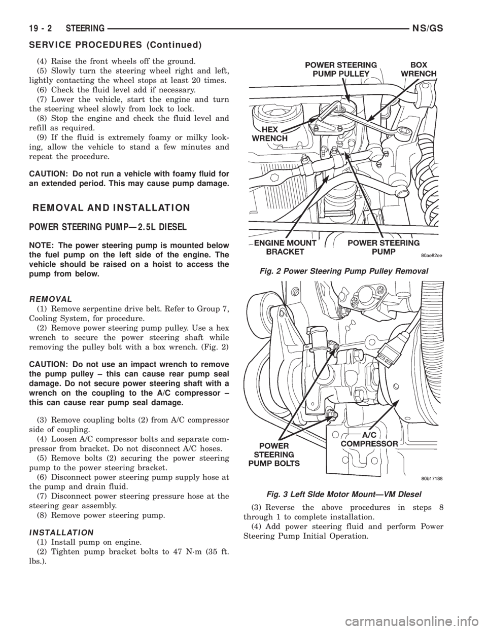
(2) Remove power steering pump pulley. Use a hex
wrench to secure the power steering shaft while
removing the pulley bolt with a box wrench. (Fig. 2)
CAUTION: Do not use an impact wrench to remove
the pump pulley ± this can cause rear pump seal
damage. Do not secure power steering shaft with a
wrench on the coupling to the A/C compressor ±
this can cause rear pump seal damage.
(3) Remove coupling bolts (2) from A/C compressor
side of coupling.
(4) Loosen A/C compressor bolts and separate com-
pressor from bracket. Do not disconnect A/C hoses.
(5) Remove bolts (2) securing the power steering
pump to the power steering bracket.
(6) Disconnect power steering pump supply hose at
the pump and drain fluid.
(7) Disconnect power steering pressure hose at the
steering gear assembly.
(8) Remove power steering pump.
INSTALLATION
(1) Install pump on engine.
(2) Tighten pump bracket bolts to 47 N´m (35 ft.
lbs.).(3) Reverse the above procedures in steps 8
through 1 to complete installation.
(4) Add power steering fluid and perform Power
Steering Pump Initial Operation.
Fig. 2 Power Steering Pump Pulley Removal
Fig. 3 Left SIde Motor MountÐVM DIesel
19 - 2 STEERINGNS/GS
SERVICE PROCEDURES (Continued)
Page 1525 of 1938
Inspect all valve springs for distortion and col-
lapsed coils. Inspect all valves and plugs for burrs,
nicks, and scores. Small nicks and scores may be
removed with crocus cloth, providing extreme care is
taken not to round off sharp edges. The sharpness of
these edges is vitally important. It prevents foreign
matter from lodging between valve and valve body.
This reduces the possibility of sticking. Inspect all
valves and plugs for freedom of operation in valve
body bores.
When bores, valves, and plugs are clean and dry,
the valves and plugs should fall freely in the bores.
The valve body bores do not change its dimensions
with use. Therefore, a valve body that was function-
ing properly when vehicle was new, will operate cor-
rectly if it is properly and thoroughly cleaned. There
is no need to replace valve body unless it is damaged
in handling.
ADJUSTMENTS
GEARSHIFT CABLE ADJUSTMENT
Lift and rotate the gearshift hand lever into the
park (P) gate position and remove the ignition key.
This confirms the shift lever is in the gated park (P)
position.
After confirming the park gate position, turn the
ignition switch. If the starter will operate, the park
gate position is correct. Move the shift lever into the
neutral (N) position. If the starter will operate in this
position, the linkage is properly adjusted. If the
starter fails to operate in either position, linkage
adjustment is required.
(1) Park the vehicle on level ground and set the
parking brake.
(2) Place the gearshift lever in park (P) gate posi-
tion and remove key.
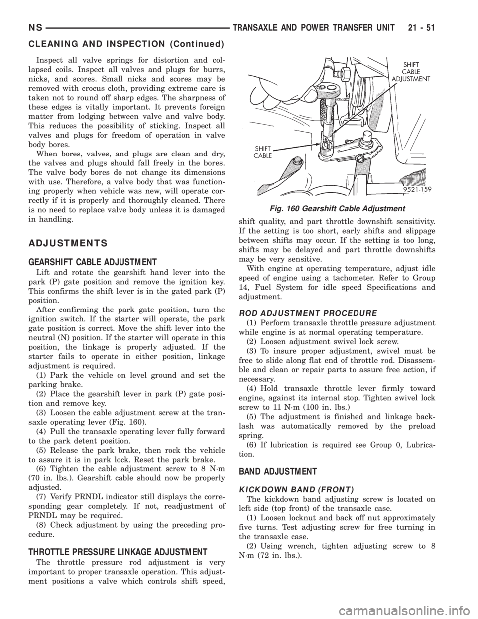
(3) Loosen the cable adjustment screw at the tran-
saxle operating lever (Fig. 160).
(4) Pull the transaxle operating lever fully forward
to the park detent position.
(5) Release the park brake, then rock the vehicle
to assure it is in park lock. Reset the park brake.
(6) Tighten the cable adjustment screw to 8 N´m
(70 in. lbs.). Gearshift cable should now be properly
adjusted.
(7) Verify PRNDL indicator still displays the corre-
sponding gear completely. If not, readjustment of
PRNDL may be required.
(8) Check adjustment by using the preceding pro-
cedure.
THROTTLE PRESSURE LINKAGE ADJUSTMENT
The throttle pressure rod adjustment is very
important to proper transaxle operation. This adjust-
ment positions a valve which controls shift speed,shift quality, and part throttle downshift sensitivity.
If the setting is too short, early shifts and slippage
between shifts may occur. If the setting is too long,
shifts may be delayed and part throttle downshifts
may be very sensitive.
With engine at operating temperature, adjust idle
speed of engine using a tachometer. Refer to Group
14, Fuel System for idle speed Specifications and
adjustment.
ROD ADJUSTMENT PROCEDURE
(1) Perform transaxle throttle pressure adjustment
while engine is at normal operating temperature.
(2) Loosen adjustment swivel lock screw.
(3) To insure proper adjustment, swivel must be
free to slide along flat end of throttle rod. Disassem-
ble and clean or repair parts to assure free action, if
necessary.
(4) Hold transaxle throttle lever firmly toward
engine, against its internal stop. Tighten swivel lock
screw to 11 N´m (100 in. lbs.)
(5) The adjustment is finished and linkage back-
lash was automatically removed by the preload
spring.
(6) I
f lubrication is required see Group 0, Lubrica-
tion.
BAND ADJUSTMENT
KICKDOWN BAND (FRONT)
The kickdown band adjusting screw is located on
left side (top front) of the transaxle case.
(1) Loosen locknut and back off nut approximately
five turns. Test adjusting screw for free turning in
the transaxle case.
(2) Using wrench, tighten adjusting screw to 8
N´m (72 in. lbs.).
Fig. 160 Gearshift Cable Adjustment
NSTRANSAXLE AND POWER TRANSFER UNIT 21 - 51
CLEANING AND INSPECTION (Continued)
Page 1721 of 1938
Improper inflation can cause:
²Uneven wear patterns
²Reduced tread life
²Reduced fuel economy
²Unsatisfactory ride
²The vehicle to drift.
Proper tire air inflation pressure specifications can
be found on the Vehicle Tire Placard provided with
the vehicle. See owner's manual.
Tire pressures have been chosen to provide safe
operation, vehicle stability, and a smooth ride. Tire
pressure should be checked cold once per month.
Check tire pressure more frequently when the
weather temperature varies widely. Tire pressure will
decrease when the outdoor temperature drops.
Tire inflation pressures specified on the placard
are always cold inflation pressure. Cold inflation
pressure is obtained after the vehicle has not been
operated for at least 3 hours, or the vehicle is driven
less than one mile after being inoperative for 3
hours. Tire inflation pressures may increase from 2
to 6 pounds per square inch (psi) during operation.
Do not reduce this normal pressure build-up.
TIRE PRESSURE FOR HIGH-SPEED DRIVING
Chrysler Corporation advocates driving at safe
speeds within posted speed limits. Where speed lim-
its allow the vehicle to be driven at high speeds, cor-
rect tire inflation pressure is very important. For
speeds up to and including 75 mph (120 km/h), tires
must be inflated to the pressures shown on the tire
placard.
Vehicles loaded to the maximum capacity should
not be driven at speeds above 75 mph (120 km/h).
For emergency vehicles that are driven at speeds
over 90 mph (144 km/h), special high-speed tires
must be used. Consult tire manufacturer for correct
inflation pressure recommendations.
REPLACEMENT TIRES
The original equipment tires provide a proper bal-
ance of many characteristics such as:
²Ride
²Noise
²Handling
²Durability
²Tread life
²Traction
²Rolling resistance
²Speed capability
It is recommend that tires equivalent to the origi-
nal equipment tires be used when replacement is
needed.
Failure to use equivalent replacement tires may
adversely affect the safety and handling of the vehicle.
The use of oversize tires not listed in the specifica-
tion charts may cause interference with vehicle com-
ponents. Under extremes of suspension and steering
travel, interference with vehicle components may
cause tire damage.
WARNING: FAILURE TO EQUIP THE VEHICLE WITH
TIRES HAVING ADEQUATE SPEED CAPABILITY
CAN RESULT IN SUDDEN TIRE FAILURE.
DIAGNOSIS AND TESTING
PRESSURE GAUGES
A quality air pressure gauge is recommended to
check tire pressure. After checking the air pressure,
replace valve cap finger tight.
TREAD WEAR INDICATORS
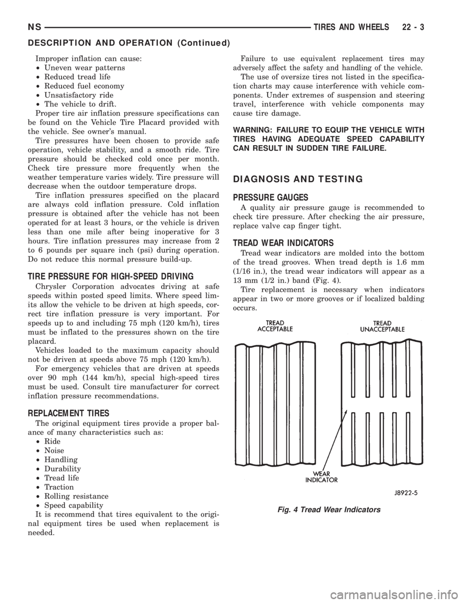
Tread wear indicators are molded into the bottom
of the tread grooves. When tread depth is 1.6 mm
(1/16 in.), the tread wear indicators will appear as a
13 mm (1/2 in.) band (Fig. 4).
Tire replacement is necessary when indicators
appear in two or more grooves or if localized balding
occurs.
Fig. 4 Tread Wear Indicators
NSTIRES AND WHEELS 22 - 3
DESCRIPTION AND OPERATION (Continued)