1996 CHRYSLER VOYAGER remove seats
[x] Cancel search: remove seatsPage 1750 of 1938
POWER SEAT SWITCH
Diagnostic information for power seat switch is
located in Group 8R, Power Seats.
REMOVAL
(1) Remove seat cushion side cover.
(2) Disconnect wire connector from power seat
switch.
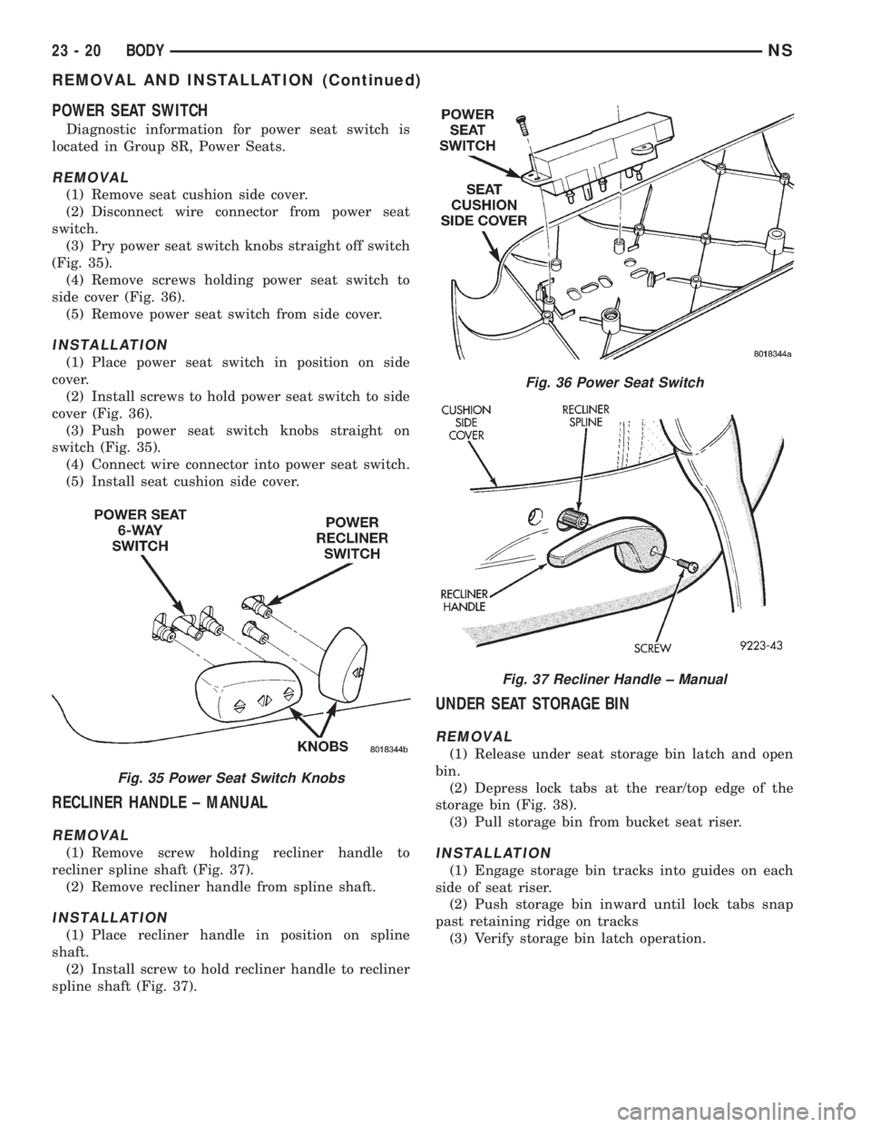
(3) Pry power seat switch knobs straight off switch
(Fig. 35).
(4) Remove screws holding power seat switch to
side cover (Fig. 36).
(5) Remove power seat switch from side cover.
INSTALLATION
(1) Place power seat switch in position on side
cover.
(2) Install screws to hold power seat switch to side
cover (Fig. 36).
(3) Push power seat switch knobs straight on
switch (Fig. 35).
(4) Connect wire connector into power seat switch.
(5) Install seat cushion side cover.
RECLINER HANDLE ± MANUAL
REMOVAL
(1) Remove screw holding recliner handle to
recliner spline shaft (Fig. 37).
(2) Remove recliner handle from spline shaft.
INSTALLATION
(1) Place recliner handle in position on spline
shaft.
(2) Install screw to hold recliner handle to recliner
spline shaft (Fig. 37).
UNDER SEAT STORAGE BIN
REMOVAL
(1) Release under seat storage bin latch and open
bin.
(2) Depress lock tabs at the rear/top edge of the
storage bin (Fig. 38).
(3) Pull storage bin from bucket seat riser.
INSTALLATION
(1) Engage storage bin tracks into guides on each
side of seat riser.
(2) Push storage bin inward until lock tabs snap
past retaining ridge on tracks
(3) Verify storage bin latch operation.
Fig. 35 Power Seat Switch Knobs
Fig. 36 Power Seat Switch
Fig. 37 Recliner Handle ± Manual
23 - 20 BODYNS
REMOVAL AND INSTALLATION (Continued)
Page 1756 of 1938
INSTALLATION
(1) Place cowl trim sill plate in position on vehicle.
(2) Engage hidden clips to hold cowl trim to cowl
panel.
(3) Install door sill plate.
FLOOR CARPET
REMOVAL
(1) Remove front seats.
(2) Remove front center console.
(3) Remove first rear seat.
(4) Remove second rear seat.
(5) Remove front cowl panels and sill plates.
(6) Remove sliding door sill plates.
(7) Remove rear door sill plate.
(8) Remove lower B-pillar trim covers.
(9) Remove D-pillar trim covers.
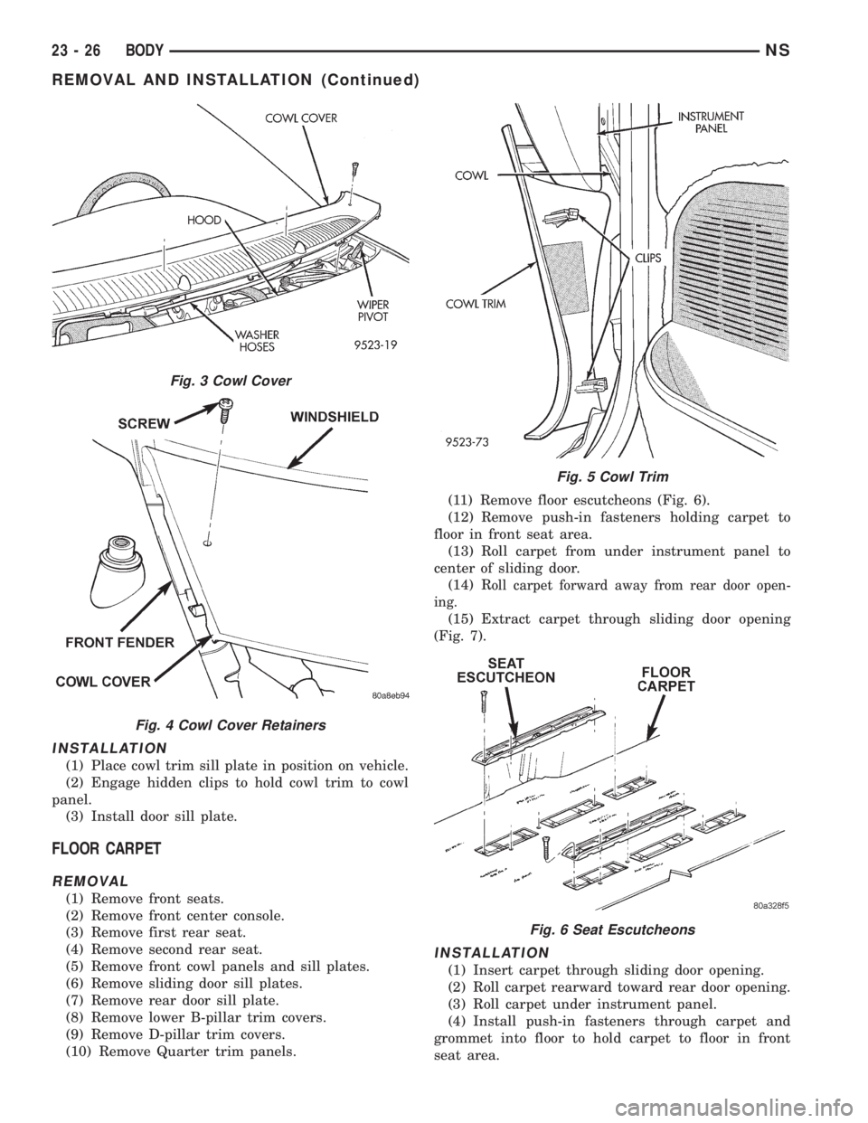
(10) Remove Quarter trim panels.(11) Remove floor escutcheons (Fig. 6).
(12) Remove push-in fasteners holding carpet to
floor in front seat area.
(13) Roll carpet from under instrument panel to
center of sliding door.
(14) R
oll carpet forward away from rear door open-
ing.
(15) Extract carpet through sliding door opening
(Fig. 7).
INSTALLATION
(1) Insert carpet through sliding door opening.
(2) Roll carpet rearward toward rear door opening.
(3) Roll carpet under instrument panel.
(4) Install push-in fasteners through carpet and
grommet into floor to hold carpet to floor in front
seat area.
Fig. 3 Cowl Cover
Fig. 4 Cowl Cover Retainers
Fig. 5 Cowl Trim
Fig. 6 Seat Escutcheons
23 - 26 BODYNS
REMOVAL AND INSTALLATION (Continued)
Page 1757 of 1938
CAUTION: Ensure that the correct fasteners are
installed in the proper locations. Damage to the fuel
tank may result.
(5) Install floor escutcheons.
(6) Install Quarter trim panels.
(7) Install D-pillar trim covers.
(8) Install lower B-pillar trim covers.
(9) Install rear door sill plate.
(10) Install sliding door sill plates.
(11) Install front cowl panels and sill plates.
(12) Install second rear seat.
(13) Install first rear seat.
(14) Install front center console.
(15) Install front seats.
FRONT DOOR
CAUTION: If the hinge pin must be removed from
the hinge, do not reuse the original pin. The struc-
tural integrity of the hinge would be reduced. Verify
availability prior to proceeding if hinge pins are to
be removed.
NOTE: The retaining clips used on the door hinge
pins are not to be re-used. Verify availability prior to
proceeding if clips are to be removed.
REMOVAL
(1) Open front door.
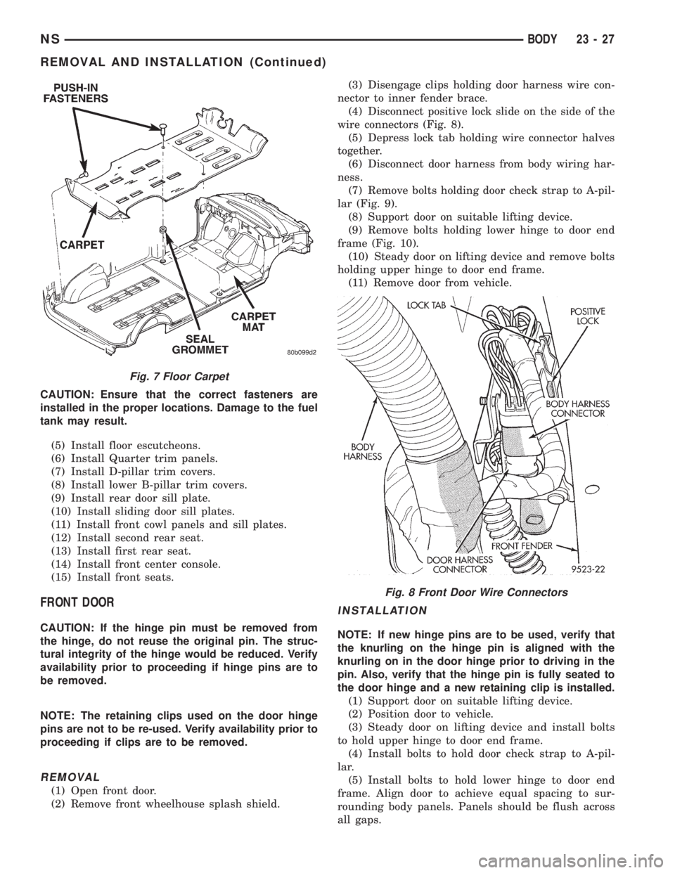
(2) Remove front wheelhouse splash shield.(3) Disengage clips holding door harness wire con-
nector to inner fender brace.
(4) Disconnect positive lock slide on the side of the
wire connectors (Fig. 8).
(5) Depress lock tab holding wire connector halves
together.
(6) Disconnect door harness from body wiring har-
ness.
(7) Remove bolts holding door check strap to A-pil-
lar (Fig. 9).
(8) Support door on suitable lifting device.
(9) Remove bolts holding lower hinge to door end
frame (Fig. 10).
(10) Steady door on lifting device and remove bolts
holding upper hinge to door end frame.
(11) Remove door from vehicle.
INSTALLATION
NOTE: If new hinge pins are to be used, verify that
the knurling on the hinge pin is aligned with the
knurling on in the door hinge prior to driving in the
pin. Also, verify that the hinge pin is fully seated to
the door hinge and a new retaining clip is installed.
(1) Support door on suitable lifting device.
(2) Position door to vehicle.
(3) Steady door on lifting device and install bolts
to hold upper hinge to door end frame.
(4) Install bolts to hold door check strap to A-pil-
lar.
(5) Install bolts to hold lower hinge to door end
frame. Align door to achieve equal spacing to sur-
rounding body panels. Panels should be flush across
all gaps.
Fig. 7 Floor Carpet
Fig. 8 Front Door Wire Connectors
NSBODY 23 - 27
REMOVAL AND INSTALLATION (Continued)
Page 1790 of 1938
NOTE: The tightening specification for all seat belt
anchor bolts is 39 N´m (29 ft. lbs.) torque.
SEAT BELT FIRST REAR OUTBOARD ± LWB FOUR
DOOR
REMOVAL
(1) Remove first and second rear seats. Refer to
Owner's manual for proper procedures.
(2) Remove shoulder harness height adjuster knob
by pulling it straight away from adjuster.
(3) Slide floor anchor cover from over the anchor
bolt.
(4) Remove floor anchor bolt.
(5) Remove anchor from floor.
(6) Open clam shell cover from over seat belt turn-
ing loop.
(7) Remove bolt holding turning loop to shoulder
belt height adjuster.
(8) Remove turning loop from C-pillar.
(9) Remove lower quarter trim panel.
(10) Route seat belt webbing and turning loop
through access hole in lower quarter trim panel.
(11) Remove bolt holding seat belt retractor to
quarter panel.
(12) Lift retractor upward and disengage arrow
head retainer holding retractor to quarter panel.
(13) Remove seat belt from vehicle.
INSTALLATION
(1) Position seat belt to vehicle.
(2) Install arrow head retainer to quarter panel
and push downward to seat retainer.
(3) Install bolt holding seat belt retractor to quar-
ter panel.
(4) Route seat belt webbing and turning loop
through access hole in lower quarter trim panel.
(5) Install lower quarter trim panel.
(6) Position turning loop to C-pillar.
(7) Install bolt holding turning loop to shoulder
belt height adjuster.
(8) Close clam shell cover from over seat belt turn-
ing loop.
(9) Position anchor to floor.
(10) Install floor anchor bolt.
(11) Slide floor anchor cover over the anchor bolt.
(12) Install shoulder harness height adjuster knob
by pushing it straight onto adjuster.
(13) Install first and second rear seats. Refer to
Owner's manual for proper procedures.
NOTE: The tightening specification for all seat belt
anchor bolts is 39 N´m (29 ft. lbs.) torque.
SEAT BELT FIRST REAR OUTBOARD ± SWB FOUR
DOOR
REMOVAL
(1) Remove first and second rear seats. Refer to
Owner's manual for proper procedures.
(2) Remove shoulder harness height adjuster knob
by pulling it straight away from adjuster.
(3) Slide floor anchor cover from over the anchor
bolt.
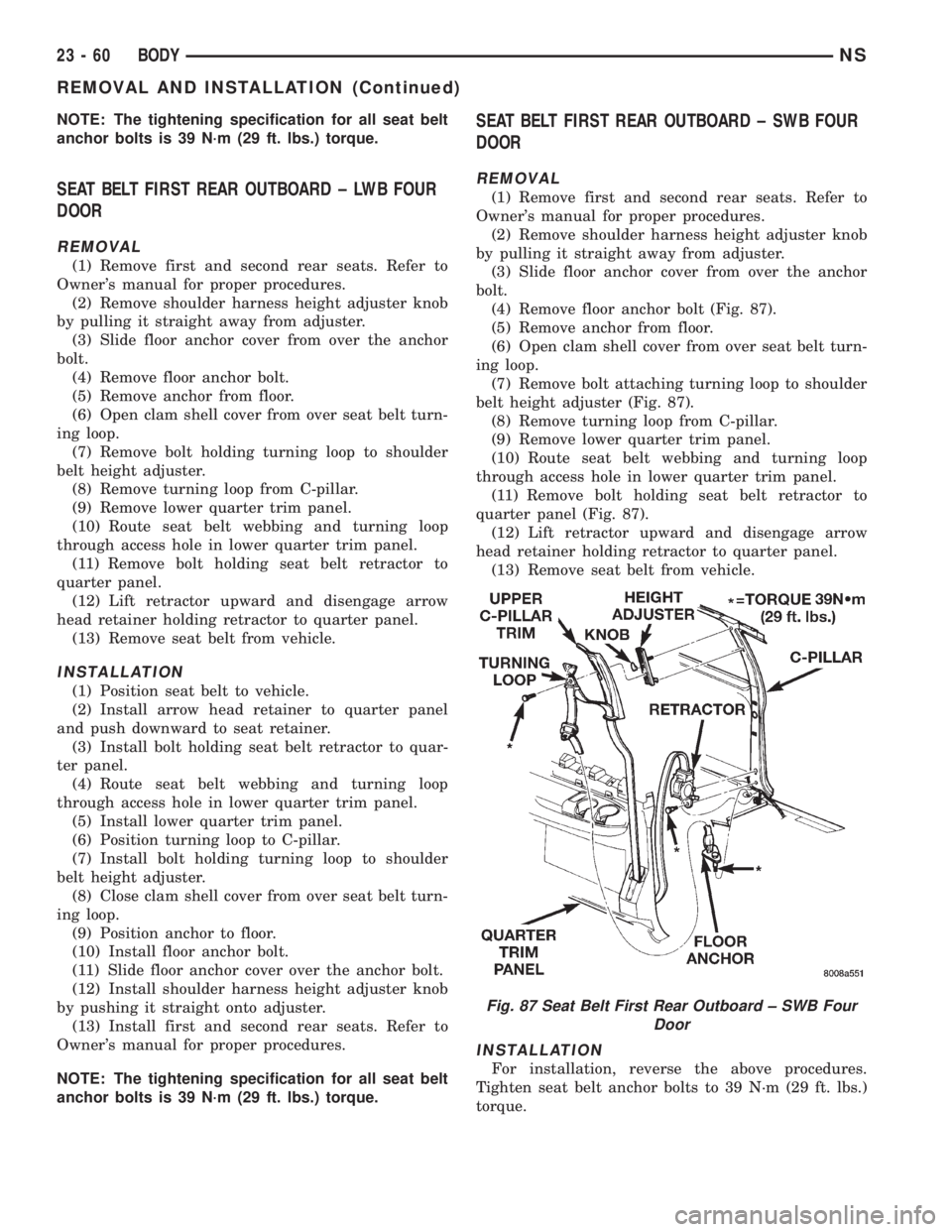
(4) Remove floor anchor bolt (Fig. 87).
(5) Remove anchor from floor.
(6) Open clam shell cover from over seat belt turn-
ing loop.
(7) Remove bolt attaching turning loop to shoulder
belt height adjuster (Fig. 87).
(8) Remove turning loop from C-pillar.
(9) Remove lower quarter trim panel.
(10) Route seat belt webbing and turning loop
through access hole in lower quarter trim panel.
(11) Remove bolt holding seat belt retractor to
quarter panel (Fig. 87).
(12) Lift retractor upward and disengage arrow
head retainer holding retractor to quarter panel.
(13) Remove seat belt from vehicle.
INSTALLATION
For installation, reverse the above procedures.
Tighten seat belt anchor bolts to 39 N´m (29 ft. lbs.)
torque.
Fig. 87 Seat Belt First Rear Outboard ± SWB Four
Door
23 - 60 BODYNS
REMOVAL AND INSTALLATION (Continued)
Page 1791 of 1938
SEAT BELT LEFT FIRST REAR OUTBOARD ± LWB
THREE DOOR
REMOVAL
(1) Remove first and second rear seats. Refer to
Owner's manual for proper procedures.
(2) Remove shoulder harness height adjuster knob
by pulling it straight away from adjuster.
(3) Slide floor anchor cover from over the anchor
bolt.
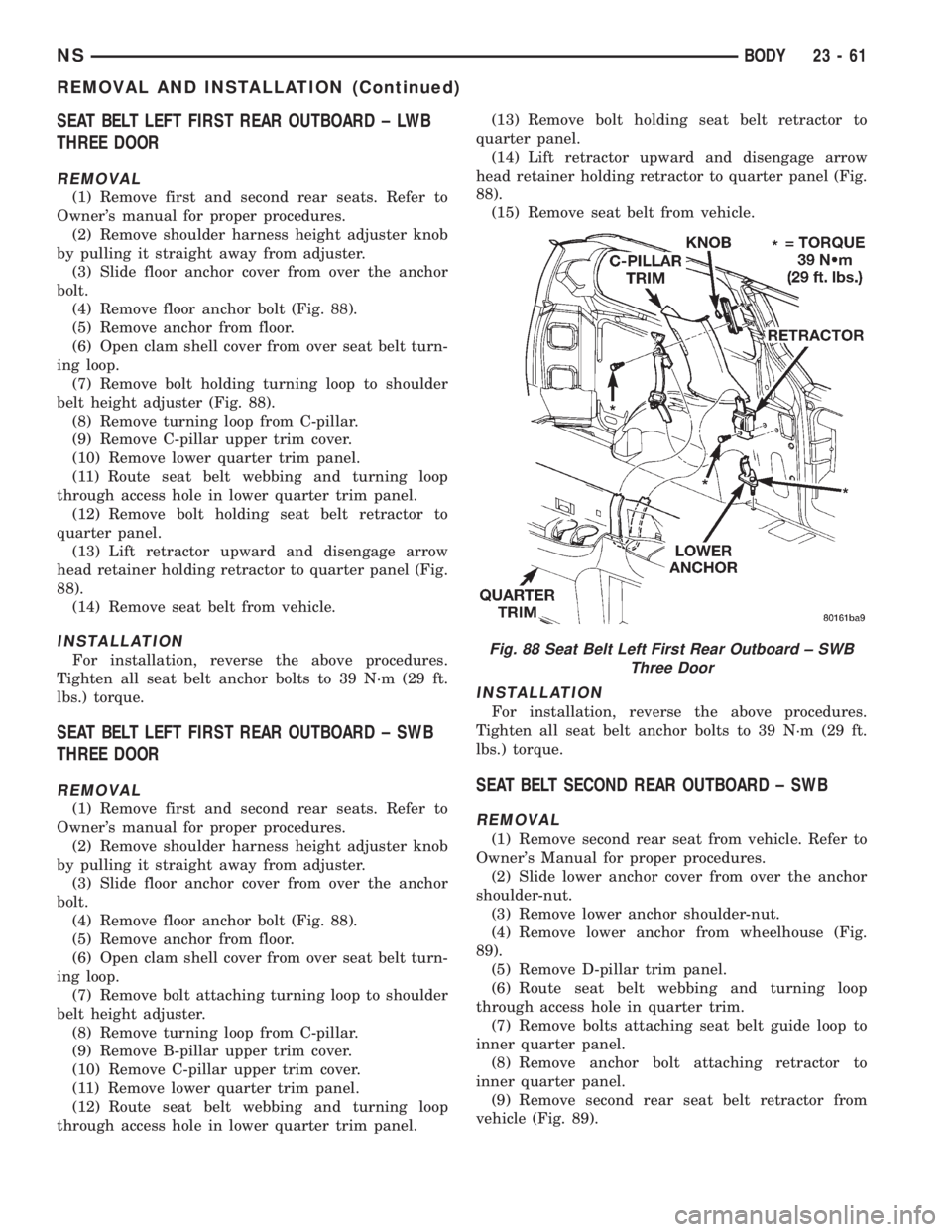
(4) Remove floor anchor bolt (Fig. 88).
(5) Remove anchor from floor.
(6) Open clam shell cover from over seat belt turn-
ing loop.
(7) Remove bolt holding turning loop to shoulder
belt height adjuster (Fig. 88).
(8) Remove turning loop from C-pillar.
(9) Remove C-pillar upper trim cover.
(10) Remove lower quarter trim panel.
(11) Route seat belt webbing and turning loop
through access hole in lower quarter trim panel.
(12) Remove bolt holding seat belt retractor to
quarter panel.
(13) Lift retractor upward and disengage arrow
head retainer holding retractor to quarter panel (Fig.
88).
(14) Remove seat belt from vehicle.
INSTALLATION
For installation, reverse the above procedures.
Tighten all seat belt anchor bolts to 39 N´m (29 ft.
lbs.) torque.
SEAT BELT LEFT FIRST REAR OUTBOARD ± SWB
THREE DOOR
REMOVAL
(1) Remove first and second rear seats. Refer to
Owner's manual for proper procedures.
(2) Remove shoulder harness height adjuster knob
by pulling it straight away from adjuster.
(3) Slide floor anchor cover from over the anchor
bolt.
(4) Remove floor anchor bolt (Fig. 88).
(5) Remove anchor from floor.
(6) Open clam shell cover from over seat belt turn-
ing loop.
(7) Remove bolt attaching turning loop to shoulder
belt height adjuster.
(8) Remove turning loop from C-pillar.
(9) Remove B-pillar upper trim cover.
(10) Remove C-pillar upper trim cover.
(11) Remove lower quarter trim panel.
(12) Route seat belt webbing and turning loop
through access hole in lower quarter trim panel.(13) Remove bolt holding seat belt retractor to
quarter panel.
(14) Lift retractor upward and disengage arrow
head retainer holding retractor to quarter panel (Fig.
88).
(15) Remove seat belt from vehicle.
INSTALLATION
For installation, reverse the above procedures.
Tighten all seat belt anchor bolts to 39 N´m (29 ft.
lbs.) torque.
SEAT BELT SECOND REAR OUTBOARD ± SWB
REMOVAL
(1) Remove second rear seat from vehicle. Refer to
Owner's Manual for proper procedures.
(2) Slide lower anchor cover from over the anchor
shoulder-nut.
(3) Remove lower anchor shoulder-nut.
(4) Remove lower anchor from wheelhouse (Fig.
89).
(5) Remove D-pillar trim panel.
(6) Route seat belt webbing and turning loop
through access hole in quarter trim.
(7) Remove bolts attaching seat belt guide loop to
inner quarter panel.
(8) Remove anchor bolt attaching retractor to
inner quarter panel.
(9) Remove second rear seat belt retractor from
vehicle (Fig. 89).
Fig. 88 Seat Belt Left First Rear Outboard ± SWB
Three Door
NSBODY 23 - 61
REMOVAL AND INSTALLATION (Continued)
Page 1813 of 1938
BODY
CONTENTS
page page
BODY COMPONENT SERVICE............... 3 SEATS .................................. 1
SEATS
INDEX
page page
REMOVAL AND INSTALLATION
BENCH SEAT BACK COVER................ 2
HEAD RESTRAINT ESCUTCHEON........... 1HEAD RESTRAINT SLEEVE................. 2
HEAD RESTRAINT........................ 1
REMOVAL AND INSTALLATION
HEAD RESTRAINT
REMOVAL
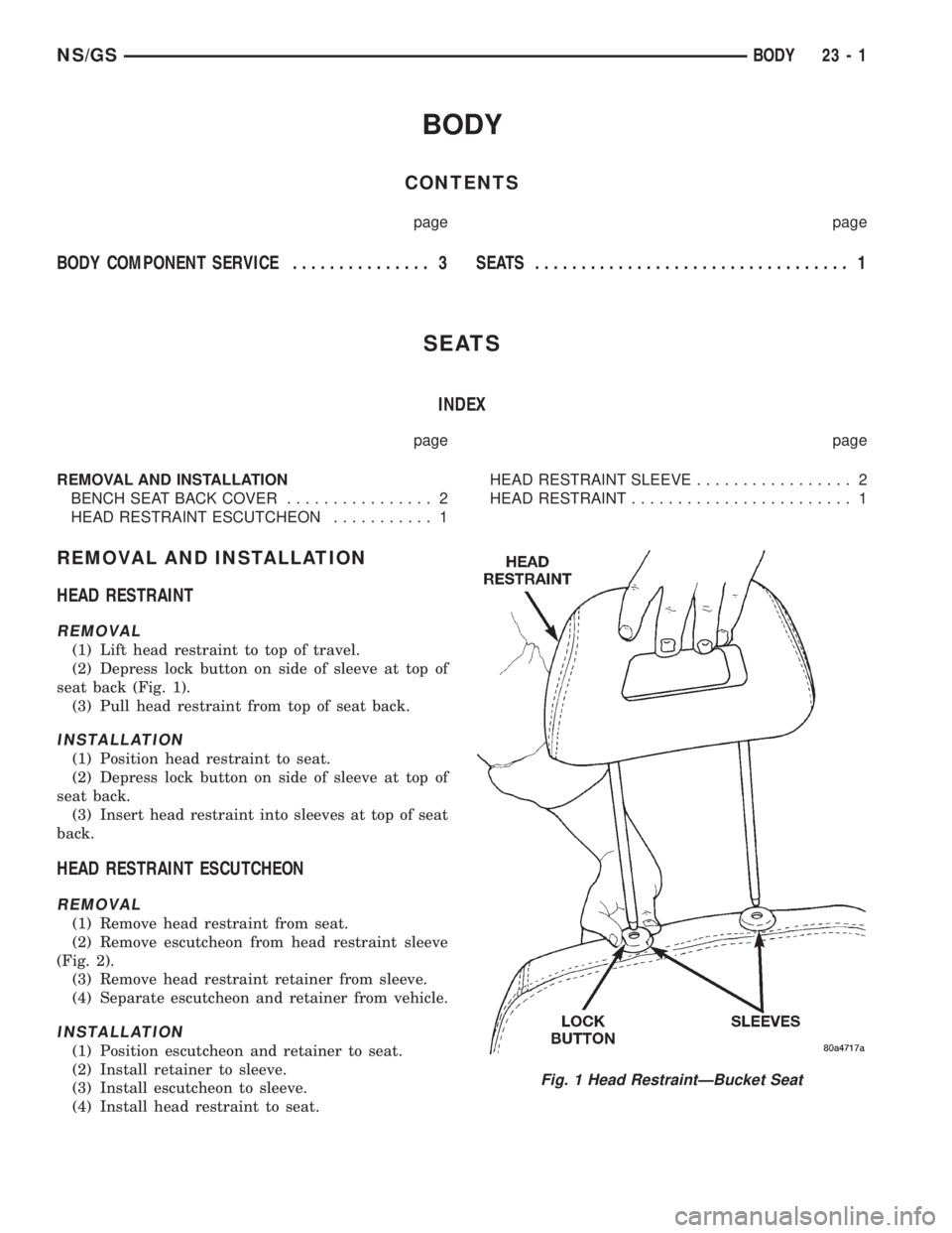
(1) Lift head restraint to top of travel.
(2) Depress lock button on side of sleeve at top of
seat back (Fig. 1).
(3) Pull head restraint from top of seat back.
INSTALLATION
(1) Position head restraint to seat.
(2) Depress lock button on side of sleeve at top of
seat back.
(3) Insert head restraint into sleeves at top of seat
back.
HEAD RESTRAINT ESCUTCHEON
REMOVAL
(1) Remove head restraint from seat.
(2) Remove escutcheon from head restraint sleeve
(Fig. 2).
(3) Remove head restraint retainer from sleeve.
(4) Separate escutcheon and retainer from vehicle.
INSTALLATION
(1) Position escutcheon and retainer to seat.
(2) Install retainer to sleeve.
(3) Install escutcheon to sleeve.
(4) Install head restraint to seat.
Fig. 1 Head RestraintÐBucket Seat
NS/GSBODY 23 - 1
Page 1819 of 1938
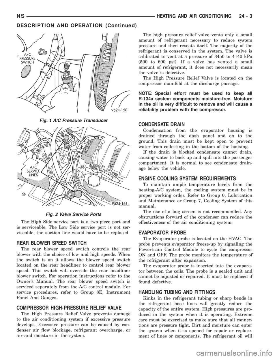
The High Side service port is a two piece port and
is serviceable. The Low Side service port is not ser-
viceable, the suction line would have to be replaced.
REAR BLOWER SPEED SWITCH
The rear blower speed switch controls the rear
blower with the choice of low and high speeds. When
the switch is on it allows the blower speed switch
located on the rear headliner to control rear blower
speed. This switch will override the rear headliner
blower switch. For operation instructions refer to the
Owner's Manual. The rear blower speed switch is
serviced separately from the A/C control module. For
service procedures, refer to Group 8E, Instrument
Panel And Gauges.
COMPRESSOR HIGH-PRESSURE RELIEF VALVE
The High Pressure Relief Valve prevents damage
to the air conditioning system if excessive pressure
develops. Excessive pressure can be caused by con-
denser air flow blockage, refrigerant overcharge, or
air and moisture in the system.The high pressure relief valve vents only a small
amount of refrigerant necessary to reduce system
pressure and then reseats itself. The majority of the
refrigerant is conserved in the system. The valve is
calibrated to vent at a pressure of 3450 to 4140 kPa
(500 to 600 psi). If a valve has vented a small
amount of refrigerant, it does not necessarily mean
the valve is defective.
The High Pressure Relief Valve is located on the
compressor manifold at the discharge passage.
NOTE: Special effort must be used to keep all
R-134a system components moisture-free. Moisture
in the oil is very difficult to remove and will cause a
reliability problem with the compressor.
CONDENSATE DRAIN
Condensation from the evaporator housing is
drained through the dash panel and on to the
ground. This drain must be kept open to prevent
water from collecting in the bottom of the housing.
If the drain is blocked condensate cannot drain,
causing water to back up and spill into the passenger
compartment. It is normal to see condensate drain-
age below the vehicle.
ENGINE COOLING SYSTEM REQUIREMENTS
To maintain ample temperature levels from the
heating-A/C system, the cooling system must be in
proper working order. Refer to Group 0, Lubrication
and Maintenance or Group 7, Cooling System of this
manual.
The use of a bug screen is not recommended. Any
obstructions forward of the condenser can reduce the
effectiveness of the air conditioning system.
EVAPORATOR PROBE
The Evaporator probe is located on the HVAC. The
probe prevents evaporator freeze-up by signaling the
Powertrain Control Module to cycle the compressor
ON and OFF. The probe monitors the temperature of
the refrigerant after expansion.
The evaporator probe is inserted into the evapora-
tor between the coils. The probe is a sealed unit and
cannot be adjusted or repaired. It must be replaced if
found defective.
HANDLING TUBING AND FITTINGS
Kinks in the refrigerant tubing or sharp bends in
the refrigerant hose lines will greatly reduce the
capacity of the entire system. High pressures are pro-
duced in the system when it is operating. Extreme
care must be exercised to make sure that all connec-
tions are pressure tight. Dirt and moisture can enter
the system when it is opened for repair or replace-
ment of lines or components. The refrigerant oil will
Fig. 1 A/C Pressure Transducer
Fig. 2 Valve Service Ports
NSHEATING AND AIR CONDITIONING 24 - 3
DESCRIPTION AND OPERATION (Continued)
Page 1869 of 1938
pressor is driven off the back of the power steering
pump. A rubber flex coupling transfers the power from
the power steering pump to the compressor clutch.
COMPRESSOR HIGH-PRESSURE RELIEF VALVE
The High Pressure Relief Valve prevents damage
to the air conditioning system if excessive pressure
develops. Excessive pressure can be caused by con-
denser air flow blockage, refrigerant overcharge, or
air and moisture in the system.
The high pressure relief valve vents only a small
amount of refrigerant necessary to reduce system
pressure and then reseats itself. The majority of the
refrigerant is conserved in the system. The valve is
calibrated to vent at a pressure of 3450 to 4140 kPa
(500 to 600 psi). If a valve has vented a small
amount of refrigerant, it does not necessarily mean
the valve is defective.
The High Pressure Relief Valve is located on the
compressor manifold at the discharge passage.
NOTE: Special effort must be used to keep all
R-134a system components moisture-free. Moisture
in the oil is very difficult to remove and will cause a
reliability problem with the compressor.
CONDENSATE DRAIN
Condensation from the evaporator housing is
drained through the dash panel and on to the
ground. This drain must be kept open to prevent
water from collecting in the bottom of the housing.
If the drain is blocked condensate cannot drain,
causing water to back up and spill into the passenger
compartment. It is normal to see condensate drain-
age below the vehicle.
ENGINE COOLING SYSTEM REQUIREMENTS
To maintain ample temperature levels from the
heating-A/C system, the cooling system must be in
proper working order. Refer to Group 0, Lubrication
and Maintenance or Group 7, Cooling System of this
manual.
The use of a bug screen is not recommended. Any
obstructions forward of the condenser can reduce the
effectiveness of the air conditioning system.
EVAPORATOR PROBE
The Evaporator probe is located on the HVAC. The
probe prevents evaporator freeze-up by signaling the
Powertrain Control Module to cycle the compressor
ON and OFF. The probe monitors the temperature of
the refrigerant after expansion.
The evaporator probe is inserted into the evapora-
tor between the coils. The probe is a sealed unit and
cannot be adjusted or repaired. It must be replaced if
found defective.
HANDLING TUBING AND FITTINGS
Kinks in the refrigerant tubing or sharp bends in
the refrigerant hose lines will greatly reduce the
capacity of the entire system. High pressures are pro-
duced in the system when it is operating. Extreme
care must be exercised to make sure that all connec-
tions are pressure tight. Dirt and moisture can enter
the system when it is opened for repair or replace-
ment of lines or components. The refrigerant oil will
absorb moisture readily out of the air. This moisture
will convert into acids within a closed system.
CAUTION: The system must be completely empty
before opening any fitting or connection in the
refrigeration system. Open fittings with caution
even after the system has been emptied. If any
pressure is noticed as a fitting is loosened,
retighten fitting and evacuate the system again.
A good rule for the flexible hose lines is to keep
the radius of all bends at least 10 times the diame-
ter of the hose. Sharper bends will reduce the flow
of refrigerant. The flexible hose lines should be
routed so they are at least 3 inches (80 mm) from
the exhaust manifold. Inspect all flexible hose lines
to make sure they are in good condition and prop-
erly routed.
The use of correct wrenches when making con-
nections is very important. Improper wrenches or
improper use of wrenches can damage the fittings.
The internal parts of the A/C system will remain
stable as long as moisture-free refrigerant and
refrigerant oil is used. Abnormal amounts of dirt,
moisture or air can upset the chemical stability.
This may cause operational troubles or even seri-
ous damage if present in more than very small
quantities.
When opening a refrigeration system, have every-
thing you will need to repair the system ready. This
will minimize the amount of time the system must
be opened. Cap or plug all lines and fittings as
soon as they are opened. This will help prevent the
entrance of dirt and moisture. All new lines and
components should be capped or sealed until they
are ready to be used.
All tools, including the refrigerant dispensing
manifold, the manifold gauge set, and test hoses
should be kept clean and dry.
HVAC CONTROL MODULE
The HVAC control module regulates the operation
of the various actuator motors. The actuator motors
are used to move the mode, blend- air, and recirc.
doors (Fig. 2).
The control module is included in the A/C control
head located on the instrument panel. The control
head includes the blower speed switch, rear wiper
NS/GSHEATING AND AIR CONDITIONING 24 - 3
DESCRIPTION AND OPERATION (Continued)