1996 CHRYSLER VOYAGER remove seats
[x] Cancel search: remove seatsPage 1233 of 1938
(3) Install cylinder head cover, torque nuts to 14.7
N´m (132 in. lbs.).
(4) Install coolant pressure tank.
(5) Install breather hose.
(6) Install generator bracket, tighten bolts to 7
N´m (4 ft. lbs.).
(7) Connect the service valves to the A/C compres-
sor ports, if equipped with air conditioning.
(8) Connect battery cable.
VALVE SPRINGSÐCYLINDER HEAD NOT
REMOVED
This procedure can be done with the engine cylin-
der head installed on the block.
REMOVAL
Each valve spring is held in place by a retainer
and a set of conical valve locks. The locks can be
removed only by compressing the valve spring.
(1) Remove the engine cylinder head cover, refer to
cylinder head cover removal in this section.
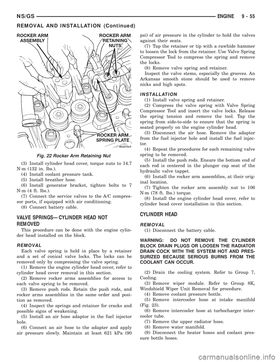
(2) Remove rocker arms assemblies for access to
each valve spring to be removed.
(3) Remove push rods. Retain the push rods, and
rocker arms assemblies in the same order and posi-
tion as removed.
(4) Inspect the springs and retainer for cracks and
possible signs of weakening.
(5) Install an air hose adaptor in the fuel injector
hole.
(6) Connect an air hose to the adapter and apply
air pressure slowly. Maintain at least 621 kPa (90psi) of air pressure in the cylinder to hold the valves
against their seats.
(7) Tap the retainer or tip with a rawhide hammer
to loosen the lock from the retainer. Use Valve Spring
Compressor Tool to compress the spring and remove
the locks.
(8) Remove valve spring and retainer.
Inspect the valve stems, especially the grooves. An
Arkansas smooth stone should be used to remove
nicks and high spots.
INSTALLATION
(1) Install valve spring and retainer.
(2) Compress the valve spring with Valve Spring
Compressor Tool and insert the valve locks. Release
the spring tension and remove the tool. Tap the
spring from side-to-side to ensure that the spring is
seated properly on the engine cylinder head.
(3) Disconnect the air hose. Remove the adaptor
from the fuel injector hole and install the fuel injec-
tor.
(4) Repeat the procedures for each remaining valve
spring to be removed.
(5) Install the push rods. Ensure the bottom end of
each rod is centered in the plunger cap seat of the
hydraulic valve tappet.
(6) Install the rocker arm assemblies, at their orig-
inal location.
(7) Tighten the rocker arm assembly nut to 106
N´m (78 ft. lbs.) torque.
(8) Install the engine cylinder head cover, refer to
cylinder head cover installation in this section.
CYLINDER HEAD
REMOVAL
(1) Disconnect the battery cable.
WARNING: DO NOT REMOVE THE CYLINDER
BLOCK DRAIN PLUGS OR LOOSEN THE RADIATOR
DRAIN COCK WITH THE SYSTEM HOT AND PRES-
SURIZED BECAUSE SERIOUS BURNS FROM THE
COOLANT CAN OCCUR.
(2) Drain the cooling system. Refer to Group 7,
Cooling.
(3) Remove wiper module. Refer to Group 8K,
Windshield Wiper Unit Removal for procedure.
(4) Remove coolant pressure bottle.
(5) Remove intercooler hose at intake manifold
(Fig. 23).
(6) Remove intercooler hose at turbocharger inter-
cooler tube.
(7) Remove the upper radiator hose.
(8) Remove water manifold.
(9) Disconnect the heater hoses and coolant pres-
sure bottle hoses.
Fig. 22 Rocker Arm Retaining Nut
NS/GSENGINE 9 - 55
REMOVAL AND INSTALLATION (Continued)
Page 1238 of 1938
(36) Operate the engine with the radiator cap off.
Inspect for leaks and continue operating the engine
until the thermostat opens. Add coolant, if required.
VALVES AND VALVE SPRINGSÐHEAD OFF
This procedure is done with the engine cylinder
head removed from the block.
REMOVAL
(1) Remove the engine cylinder head from the cyl-
inder block. Refer to cylinder head removal in this
section.
(2) Use Valve Spring Compressor Tool and com-
press each valve spring.
(3) Remove the valve locks, retainers, and springs.
(4) Use an Arkansas smooth stone or a jewelers
file to remove any burrs on the top of the valve stem,
especially around the groove for the locks.
(5) Remove the valves, and place them in a rack in
the same order as removed.
INSTALLATION
(1) Fit each valve to its respective valve guide.
NOTE: If valves and valve seats have been refaced
refer to Service Procedures in this section. Follow
The Valve Stand Down procedure.
(2) Install lower, washer and spring.
(3) Install upper spring collar, and compress valve
spring with spring compressor tool. Install split cone
retainers.
HYDRAULIC TAPPETS
REMOVAL
(1) Remove coolant pressure bottle.
(2) Remove cylinder head cover. Refer to cylinder
head cover removal in this section.
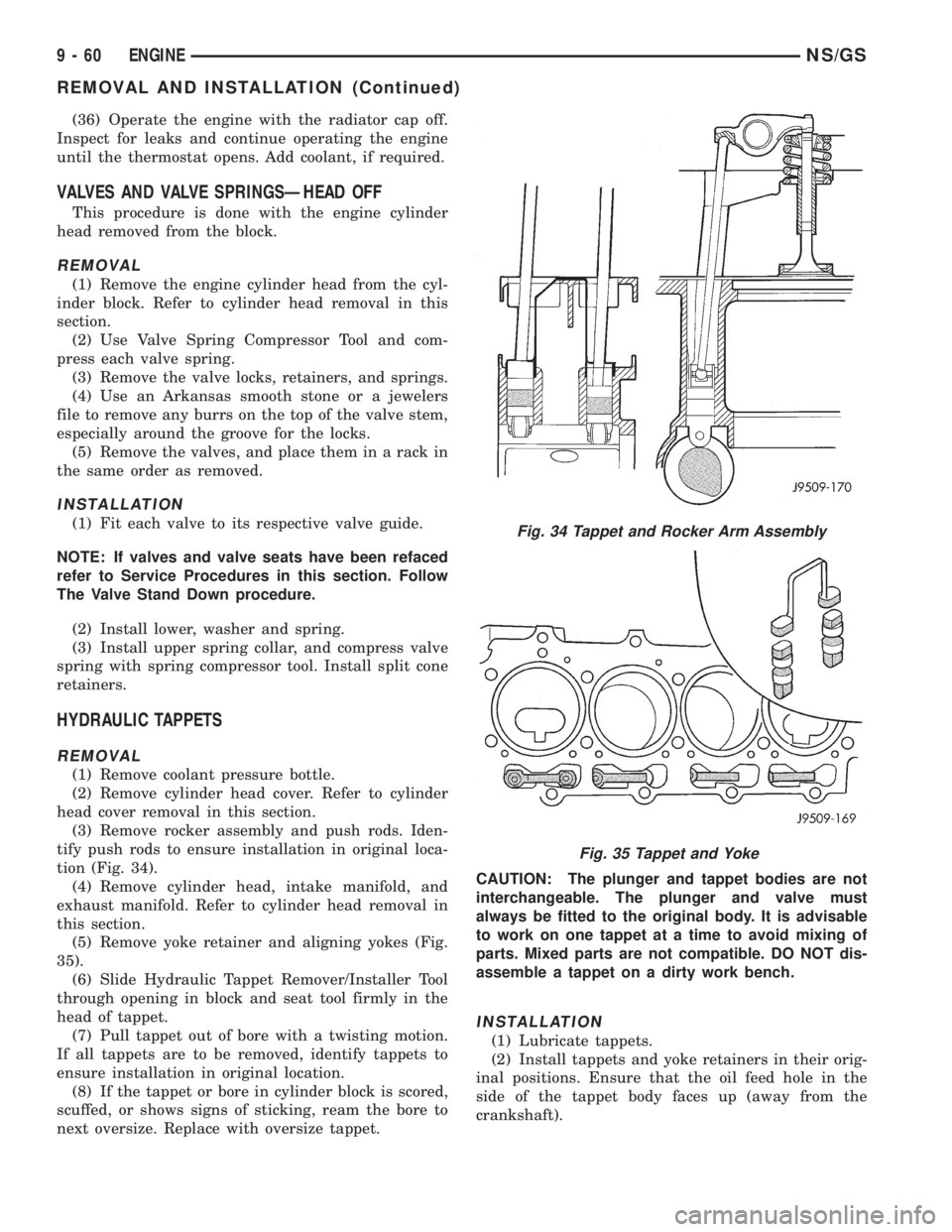
(3) Remove rocker assembly and push rods. Iden-
tify push rods to ensure installation in original loca-
tion (Fig. 34).
(4) Remove cylinder head, intake manifold, and
exhaust manifold. Refer to cylinder head removal in
this section.
(5) Remove yoke retainer and aligning yokes (Fig.
35).
(6) Slide Hydraulic Tappet Remover/Installer Tool
through opening in block and seat tool firmly in the
head of tappet.
(7) Pull tappet out of bore with a twisting motion.
If all tappets are to be removed, identify tappets to
ensure installation in original location.
(8) If the tappet or bore in cylinder block is scored,
scuffed, or shows signs of sticking, ream the bore to
next oversize. Replace with oversize tappet.CAUTION: The plunger and tappet bodies are not
interchangeable. The plunger and valve must
always be fitted to the original body. It is advisable
to work on one tappet at a time to avoid mixing of
parts. Mixed parts are not compatible. DO NOT dis-
assemble a tappet on a dirty work bench.
INSTALLATION
(1) Lubricate tappets.
(2) Install tappets and yoke retainers in their orig-
inal positions. Ensure that the oil feed hole in the
side of the tappet body faces up (away from the
crankshaft).
Fig. 34 Tappet and Rocker Arm Assembly
Fig. 35 Tappet and Yoke
9 - 60 ENGINENS/GS
REMOVAL AND INSTALLATION (Continued)
Page 1380 of 1938
FUEL HEATER RELAY TEST
The fuel heater relay is located in the Power Dis-
tribution Center (PDC). Refer to RelaysÐOperation/
Testing in Fuel Ingection System section of this
group for test procedures.
FUEL INJECTOR TEST
The fuel injection nozzels, located on the engine
cylinder head, spray fuel under high pressure into
the individual combustion chambers. Pressurized
fuel, delivered by the fuel injection pump, unseats a
spring-loaded needle valve inside the injector, and
the fuel is atomized as it escapes through the injector
opening into the engine's combustion chamber. If the
fuel injector does not operate properly, the engine
may misfire, or cause other driveability problems.
A leak in the injection pump±to±injector high±pres-
sure fuel line can cause many of the same symptoms
as a malfunctioning injector. Inspect for a leak in the
high±pressure lines before checking for a malfunc-
tioning fuel injector.
WARNING: THE INJECTION PUMP SUPPLIES HIGH-
±PRESSURE FUEL OF UP TO APPROXIMATELY
45,000 KPA (6526 PSI) TO EACH INDIVIDUAL INJEC-
TOR THROUGH THE HIGH±PRESSURE LINES. FUEL
UNDER THIS AMOUNT OF PRESSURE CAN PENE-
TRATE THE SKIN AND CAUSE PERSONAL INJURY.
WEAR SAFETY GOGGLES AND ADEQUATE PRO-
TECTIVE CLOTHING. AVOID CONTACT WITH FUEL
SPRAY WHEN BLEEDING HIGH±PRESSURE FUEL
LINES.
WARNING: DO NOT BLEED AIR FROM THE FUEL
SYSTEM OF A HOT ENGINE. DO NOT ALLOW FUEL
TO SPRAY ONTO THE EXHAUST MANIFOLD WHEN
BLEEDING AIR FROM THE FUEL SYSTEM.
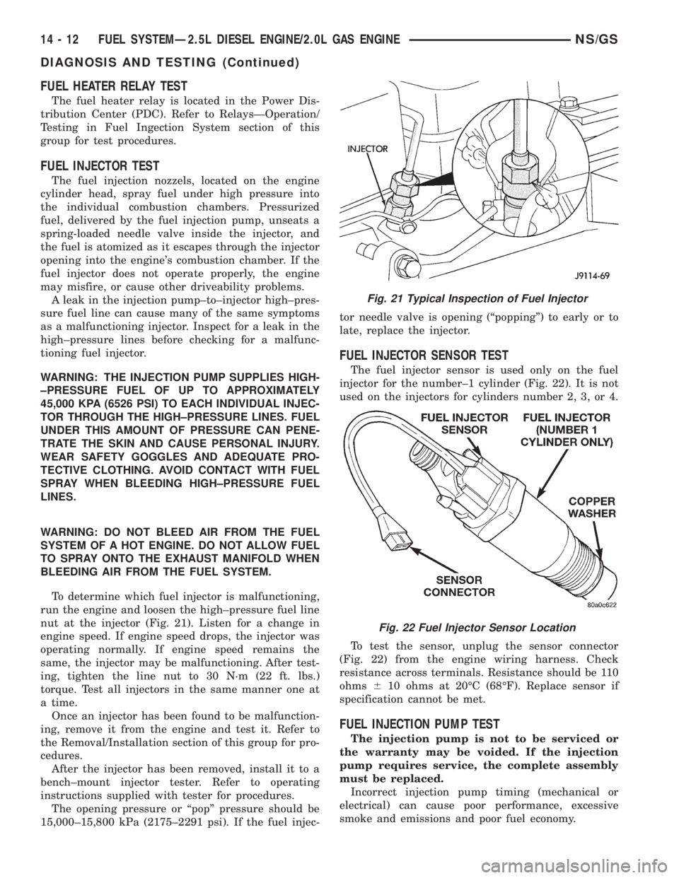
To determine which fuel injector is malfunctioning,
run the engine and loosen the high±pressure fuel line
nut at the injector (Fig. 21). Listen for a change in
engine speed. If engine speed drops, the injector was
operating normally. If engine speed remains the
same, the injector may be malfunctioning. After test-
ing, tighten the line nut to 30 N´m (22 ft. lbs.)
torque. Test all injectors in the same manner one at
a time.
Once an injector has been found to be malfunction-
ing, remove it from the engine and test it. Refer to
the Removal/Installation section of this group for pro-
cedures.
After the injector has been removed, install it to a
bench±mount injector tester. Refer to operating
instructions supplied with tester for procedures.
The opening pressure or ªpopº pressure should be
15,000±15,800 kPa (2175±2291 psi). If the fuel injec-tor needle valve is opening (ªpoppingº) to early or to
late, replace the injector.
FUEL INJECTOR SENSOR TEST
The fuel injector sensor is used only on the fuel
injector for the number±1 cylinder (Fig. 22). It is not
used on the injectors for cylinders number 2, 3, or 4.
To test the sensor, unplug the sensor connector
(Fig. 22) from the engine wiring harness. Check
resistance across terminals. Resistance should be 110
ohms610 ohms at 20ÉC (68ÉF). Replace sensor if
specification cannot be met.
FUEL INJECTION PUMP TEST
The injection pump is not to be serviced or
the warranty may be voided. If the injection
pump requires service, the complete assembly
must be replaced.
Incorrect injection pump timing (mechanical or
electrical) can cause poor performance, excessive
smoke and emissions and poor fuel economy.
Fig. 21 Typical Inspection of Fuel Injector
Fig. 22 Fuel Injector Sensor Location
14 - 12 FUEL SYSTEMÐ2.5L DIESEL ENGINE/2.0L GAS ENGINENS/GS
DIAGNOSIS AND TESTING (Continued)
Page 1729 of 1938
SERVICE PROCEDURES
WHEEL INSTALLATION
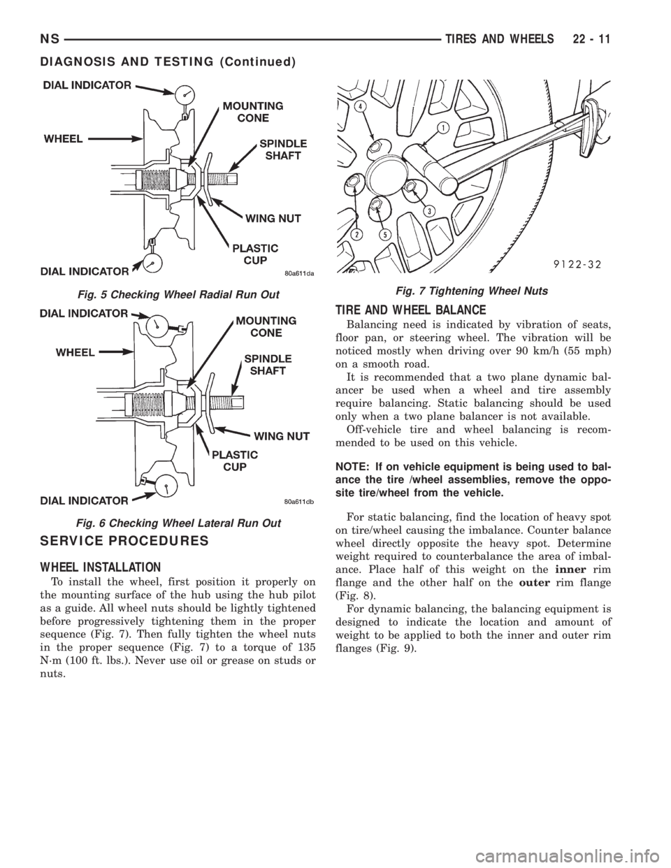
To install the wheel, first position it properly on
the mounting surface of the hub using the hub pilot
as a guide. All wheel nuts should be lightly tightened
before progressively tightening them in the proper
sequence (Fig. 7). Then fully tighten the wheel nuts
in the proper sequence (Fig. 7) to a torque of 135
N´m (100 ft. lbs.). Never use oil or grease on studs or
nuts.
TIRE AND WHEEL BALANCE
Balancing need is indicated by vibration of seats,
floor pan, or steering wheel. The vibration will be
noticed mostly when driving over 90 km/h (55 mph)
on a smooth road.
It is recommended that a two plane dynamic bal-
ancer be used when a wheel and tire assembly
require balancing. Static balancing should be used
only when a two plane balancer is not available.
Off-vehicle tire and wheel balancing is recom-
mended to be used on this vehicle.
NOTE: If on vehicle equipment is being used to bal-
ance the tire /wheel assemblies, remove the oppo-
site tire/wheel from the vehicle.
For static balancing, find the location of heavy spot
on tire/wheel causing the imbalance. Counter balance
wheel directly opposite the heavy spot. Determine
weight required to counterbalance the area of imbal-
ance. Place half of this weight on theinnerrim
flange and the other half on theouterrim flange
(Fig. 8).
For dynamic balancing, the balancing equipment is
designed to indicate the location and amount of
weight to be applied to both the inner and outer rim
flanges (Fig. 9).
Fig. 5 Checking Wheel Radial Run Out
Fig. 6 Checking Wheel Lateral Run Out
Fig. 7 Tightening Wheel Nuts
NSTIRES AND WHEELS 22 - 11
DIAGNOSIS AND TESTING (Continued)
Page 1731 of 1938
BODY
CONTENTS
page page
BODY COMPONENT SERVICE.............. 22
GENERAL SERVICE INFORMATION........... 1
PAINT.................................. 2SEATS .................................. 9
STATIONARY GLASS....................... 4
GENERAL SERVICE INFORMATION
INDEX
page
GENERAL INFORMATION
SAFETY PRECAUTIONS AND WARNINGS...... 1
GENERAL INFORMATION
SAFETY PRECAUTIONS AND WARNINGS
WARNING: EYE PROTECTION SHOULD BE USED
WHEN SERVICING GLASS COMPONENTS. PER-
SONAL INJURY CAN RESULT.
USE A OSHA APPROVED BREATHING FILTER
WHEN SPRAYING PAINT OR SOLVENTS IN A CON-
FINED AREA. PERSONAL INJURY CAN RESULT.
AVOID PROLONGED SKIN CONTACT WITH
PETROLEUM OR ALCOHOL± BASED CLEANING
SOLVENTS. PERSONAL INJURY CAN RESULT.
DO NOT STAND UNDER A HOISTED VEHICLE
THAT IS NOT PROPERLY SUPPORTED ON SAFETY
STANDS. PERSONAL INJURY CAN RESULT.
CAUTION: When holes must be drilled or punched
in an inner body panel, verify depth of space to the
outer body panel, electrical wiring, or other compo-
nents. Damage to vehicle can result.
Do not weld exterior panels unless combustible
material on the interior of vehicle is removed from
the repair area. Fire or hazardous conditions, can
result.
Always have a fire extinguisher ready for use
when welding.
Disconnect the negative (-) cable clamp from the
battery when servicing electrical components that
are live when the ignition is OFF. Damage to electri-
cal system can result.Do not use abrasive chemicals or compounds on
painted surfaces. Damage to finish can result.
Do not use harsh alkaline based cleaning sol-
vents on painted or upholstered surfaces. Damage
to finish or color can result.
Do not hammer or pound on plastic trim panel
when servicing interior trim. Plastic panels can
break.
Chrysler Corporation uses many different types of
push-in fasteners to secure the interior and exterior
trim to the body. Most of these fasteners can be
reused to assemble the trim during various repair
procedures. At times, a push-in fastener cannot be
removed without damaging the fastener or the com-
ponent it is holding. If it is not possible to remove a
fastener without damaging a component or body, cut
or break the fastener and use a new one when
installing the component. Never pry or pound on a
plastic or pressed-board trim component. Using a
suitable fork-type prying device, pry the fastener
from the retaining hole behind the component being
removed. When installing, verify fastener alignment
with the retaining hole by hand. Push directly on or
over the fastener until it seats. Apply a low-force pull
to the panel to verify that it is secure.
When it is necessary to remove components to ser-
vice another, it should not be necessary to apply
excessive force or bend a component to remove it.
Before damaging a trim component, verify hidden
fasteners or captured edges holding the component in
place.
NSBODY 23 - 1
Page 1739 of 1938
SEATS
INDEX
page page
REMOVAL AND INSTALLATION
ARM REST.............................. 9
BENCH SEAT BACK COVER................ 9
BENCH SEAT BACK HINGE COVERS........ 10
BENCH SEAT BACK HINGE................. 9
BENCH SEAT RISER ± FIRST REAR......... 11
BENCH SEAT RISER ± SECOND REAR....... 11
BENCH SEAT TRACK ± SECOND REAR...... 11
BUCKET SEAT BACK ASSIST STRAP........ 12
BUCKET SEAT BACK..................... 12
BUCKET SEAT CUSHION PAN.............. 12
BUCKET SEAT CUSHION SIDE COVER....... 13
BUCKET SEAT RECLINER ± MANUAL........ 13
BUCKET SEAT RECLINER ± POWER......... 14
BUCKET SEAT RISER ± MANUAL TRACK..... 14
BUCKET SEAT TRACK FRONT COVER ±
POWER.............................. 15BUCKET SEAT TRACK REAR COVER ±
POWER.............................. 15
BUCKET SEAT TRACK ± MANUAL........... 14
BUCKET SEAT TRACK ± POWER........... 14
CHILD RESTRAINT SEAT MODULE.......... 16
HEAD RESTRAINT SLEEVE................ 18
HEAD RESTRAINT ± BENCH SEAT.......... 16
HEAD RESTRAINT ± BUCKET SEAT......... 17
HEATED SEAT HEATING ELEMENT.......... 18
HEATED SEAT MODULE.................. 18
HEATED SEAT SWITCH................... 19
MECHANICAL LUMBAR HANDLE ASSEMBLY . . 19
PLASTIC GROCERY BAG RETAINER......... 19
POWER SEAT SWITCH................... 20
RECLINER HANDLE ± MANUAL............. 20
UNDER SEAT STORAGE BIN GUIDE......... 21
UNDER SEAT STORAGE BIN LOCK/LATCH.... 21
UNDER SEAT STORAGE BIN............... 20
REMOVAL AND INSTALLATION
ARM REST
REMOVAL
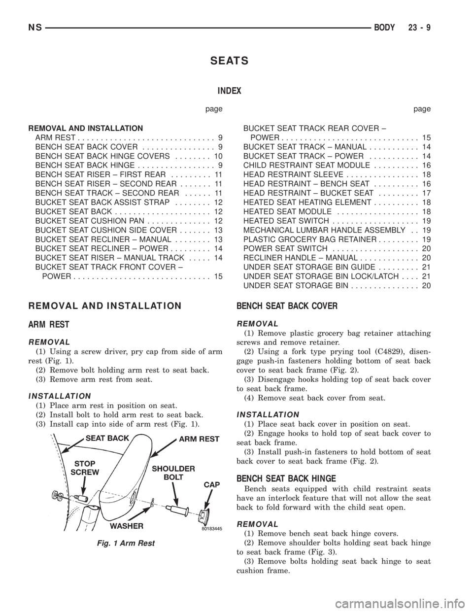
(1) Using a screw driver, pry cap from side of arm
rest (Fig. 1).
(2) Remove bolt holding arm rest to seat back.
(3) Remove arm rest from seat.
INSTALLATION
(1) Place arm rest in position on seat.
(2) Install bolt to hold arm rest to seat back.
(3) Install cap into side of arm rest (Fig. 1).
BENCH SEAT BACK COVER
REMOVAL
(1) Remove plastic grocery bag retainer attaching
screws and remove retainer.
(2) Using a fork type prying tool (C4829), disen-
gage push-in fasteners holding bottom of seat back
cover to seat back frame (Fig. 2).
(3) Disengage hooks holding top of seat back cover
to seat back frame.
(4) Remove seat back cover from seat.
INSTALLATION
(1) Place seat back cover in position on seat.
(2) Engage hooks to hold top of seat back cover to
seat back frame.
(3) Install push-in fasteners to hold bottom of seat
back cover to seat back frame (Fig. 2).
BENCH SEAT BACK HINGE
Bench seats equipped with child restraint seats
have an interlock feature that will not allow the seat
back to fold forward with the child seat open.
REMOVAL
(1) Remove bench seat back hinge covers.
(2) Remove shoulder bolts holding seat back hinge
to seat back frame (Fig. 3).
(3) Remove bolts holding seat back hinge to seat
cushion frame.
Fig. 1 Arm Rest
NSBODY 23 - 9
Page 1748 of 1938
INSTALLATION
For installation, reverse the above procedures.
HEAD RESTRAINT SLEEVE
REMOVAL
(1) Remove head restraint.
(2) Disengage closure holding bottom of trim cover
together.
(3) Reach under trim cover through opening at
bottom of seat back.
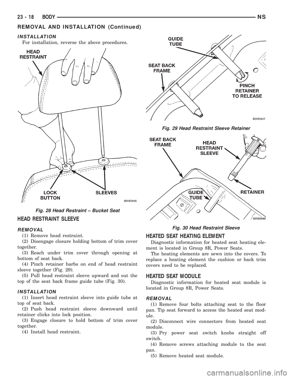
(4) Pinch retainer barbs on end of head restraint
sleeve together (Fig. 29).
(5) Pull head restraint sleeve upward and out the
top of the seat back frame guide tube (Fig. 30).
INSTALLATION
(1) Insert head restraint sleeve into guide tube at
top of seat back.
(2) Push head restraint sleeve downward until
retainer clicks into lock position.
(3) Engage closure to hold bottom of trim cover
together.
(4) Install head restraint.
HEATED SEAT HEATING ELEMENT
Diagnostic information for heated seat heating ele-
ment is located in Group 8R, Power Seats.
The heating elements are sewn into the covers. To
replace a heating element the cushion or back trim
covers need to be replaced.
HEATED SEAT MODULE
Diagnostic information for heated seat module is
located in Group 8R, Power Seats.
REMOVAL
(1) Remove four bolts attaching seat to the floor
pan. Tip seat forward to access the heated seat mod-
ule.
(2) Disconnect wire connectors from heated seat
module.
(3) Pry power seat switch knobs straight off
switch.
(4) Remove screws attaching module to the seat
pan.
(5) Remove heated seat module.
Fig. 28 Head Restraint ± Bucket Seat
Fig. 29 Head Restraint Sleeve Retainer
Fig. 30 Head Restraint Sleeve
23 - 18 BODYNS
REMOVAL AND INSTALLATION (Continued)
Page 1749 of 1938
INSTALLATION
(1) Place heated seat module in position on seat
pan.
(2) Install module attaching screws.
(3) Connect module wire connectors.
(4) Install seat.
HEATED SEAT SWITCH
Diagnostic information for heated seat switch is
located in Group 8R, Power Seats.
REMOVAL
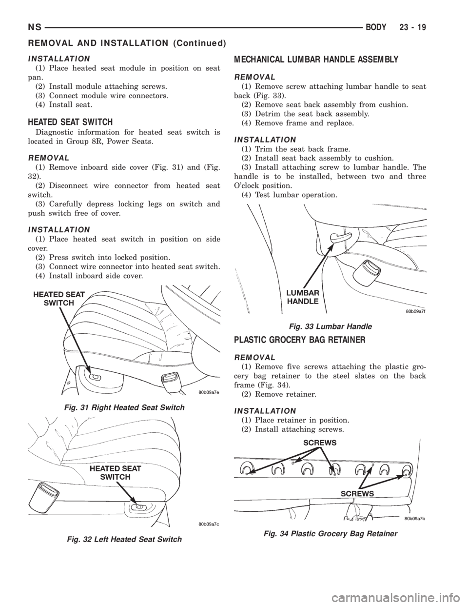
(1) Remove inboard side cover (Fig. 31) and (Fig.
32).
(2) Disconnect wire connector from heated seat
switch.
(3) Carefully depress locking legs on switch and
push switch free of cover.
INSTALLATION
(1) Place heated seat switch in position on side
cover.
(2) Press switch into locked position.
(3) Connect wire connector into heated seat switch.
(4) Install inboard side cover.
MECHANICAL LUMBAR HANDLE ASSEMBLY
REMOVAL
(1) Remove screw attaching lumbar handle to seat
back (Fig. 33).
(2) Remove seat back assembly from cushion.
(3) Detrim the seat back assembly.
(4) Remove frame and replace.
INSTALLATION
(1) Trim the seat back frame.
(2) Install seat back assembly to cushion.
(3) Install attaching screw to lumbar handle. The
handle is to be installed, between two and three
O'clock position.
(4) Test lumbar operation.
PLASTIC GROCERY BAG RETAINER
REMOVAL
(1) Remove five screws attaching the plastic gro-
cery bag retainer to the steel slates on the back
frame (Fig. 34).
(2) Remove retainer.
INSTALLATION
(1) Place retainer in position.
(2) Install attaching screws.
Fig. 31 Right Heated Seat Switch
Fig. 32 Left Heated Seat Switch
Fig. 33 Lumbar Handle
Fig. 34 Plastic Grocery Bag Retainer
NSBODY 23 - 19
REMOVAL AND INSTALLATION (Continued)